a surrogate framework for personal a thesis
TRANSCRIPT
A SURROGATE FRAMEWORK FOR PERSONAL
PROFILE DEVICES
by
MUKUNDAN DESIKAN, B.E.
A THESIS
IN
COMPUTER SCIENCE
Submitted to the Graduate Faculty of Texas Tech University in
Partial Fulfillment of the Requirements for
the Degree of
MASTER OF SCIENCE
Approved
Chairperson of the Committee
Accepted
Dean of the Graduate School
December, 2004

ACKNOWLEDGEMENTS
I would like to express my sincere gratitude to Dr. Michael Sobolewski, the
chairperson of my committee, for giving an opportunity to work with him. I am
extremely thankful to him for all his support and guidance and for dedicating his time in
spite of his busy schedule towards successful completion of my thesis research. 1 feel
gratefiil for his appreciation and constant encouragement with new ideas which were
inherent in successfully designing the solution for my thesis problem. Without him the
whole research definitely would have been an incomplete work.
I feel glad to thank Dr. Hector Hemandez for having accepted to be in my
committee. As a graduate advisor and a committee member he has always shown extreme
interest towards my academic work by clearly defining the standards and deadlines. I
would like to thank him for his full cooperation and support for successful completion of
my thesis research and graduation.
I am extremely obliged to have Dr. Jean Strahlendorf from the Department of
Physiology as my committee member who has given me intense moral support during the
entire course of my research. I feel grateful in thanking her for all the encouragement and
interest she has shown towards my research.
I would definitely like to thank my parents for all the support they have shown to
me throughout my entire education. I like to express my heartfelt appreciation to all my
friends in SORCER lab and Physiology for their timely help and encouragement.

TABLE OF CONTENTS
ACKNOWLEDGEMENTS n
TABLE OF CONTENTS in
TABLE OF FIGURES vn
ABSTRACT ix
CHAPTER
1. INTRODUCTION 1
1.1 Challenges 2
1.2 Motivation 4
2. SERVICE ORIENTED ARCHITECTURE (SOA) 6
2.1 Key Components of SOA 6
2.1.1 Service 7
2.1.2 Message 7
2.1.3 Directory Service 7
2.1.4 Web Service 8
2.2 Service - Oriented Programming (SOP) 8
2.3 Service Oriented Computing Envirorunent(SORCER) 10
2.3.1 Framework 10
2.3.2 Design 12
2.4 SORCER Programming Paradigm 16
3. J2ME AND JU^I 19
3.1 Java 2 Micro Edition (J2ME) 19
i l l

3.1.1 Uitroduction 19
3.1.2 Architecture 19
3.1.3 Benefits 22
3.2 Jini Network Technology 23
3.2.1 Introduction 23
3.2.2 Goals of Jini 25
3.2.3 Architecture 26
3.2.4 Infrastmcture 30
3.2.5 Programming model 31
3.2.6 Services 32
4. JINI SURROGATE ARCHITECTURE 37
4.1 Uitroduction 37
4.2 Requirements 37
4.3 Terms and Definitions 41
4.4 Architecture 42
4.4.2 Discovery and Surrogate Loading 43
4.4.3 Surrogate Execution 44
4.4.4 Liveness 45
4.5 Interconnect 46
4.5.1 Requirements 46
4.6 IP Interconnect 48
4.6.1 Overview 48
IV

4.6.2 Discovery protocols 49
4.6.3 Discovery using IP Interconnect 54
4.6.4 SuiTogate Retrieval 55
4.6.5 Reg:istration using IP Interconnect 57
4.6.6 Surrogate Reachability 57
4.7 Surrogate Packaging 58
4.8 Madison Surrogate Host 59
4.8.1 Design 59
4.8.2 Modules 59
4.8.3 SuiTogate Registration and Activation 61
4.8.4 Surrogate Deactivation 62
4.8.5 Multiple surrogates 63
4.8.6 Multiple Adapters 63
5. SPPG FRAMEWORK 65
5.1 Introduction 65
5.2 Objective/Approach 65
5.3 Gateway 67
5.3.1 Requirements 67
5.3.2 Advantages of using gateways 67
5.4 PP Devices-Service Consumers 68
5.5 PP Devices-Service Providers 69
5.6 Advantages 72

5.7 Framework Design 72
5.7.1 Generic Gateways 72
5.7.2 Generic Service Provider 75
5.8 Implementation 76
5.8.1 Technical Architecture 77
5.8.2 Package Diagrams 77
5.8.3 Physical Architecture 79
5.9 Validation 79
5.9.1 PDA as Image Requestor 80
5.9.2 PDA As Photo Album Provider 81
5.9.3 Client using Surrogate Service 83
5.9.4 Testing and Results 83
5.10 Conclusions 84
5.11 Future Research 85
GLOSSARY/ABBREVATIONS 86
REFERENCES 87
VI

TABLE OF FIGURES
2J, UML-Diagram for the service-based framework 13
2 ^ Operation of the Service Broker and Service Provider 15
3.1 J2ME Architecture 20
3.2 Jini-Platform Independent 23
3.3 Discovery 33
3.4 Join 34
3.5 Lookup 34
3.6 Service Invocation 35
4.1 Jini Enabled device 38
4.2 Device Architecture for non-Jini devices 40
4.3 Initial state of Surrogate Architecture 43
4.4 Discovery and Surrogate Loading 44
4.5 Surrogate Execution 45
4.6 Multicast Host Announcement 50
4.7 Multicast Host Request protocol 52
4.8 Discovery using IP Interconnect 54
4.9 Registration using IP Interconnect 57
4.10 Module interaction in Madison 60
4.11 Surrogate registration and Activvation 61
4.12 Multiple Sun-Qgate Threads 63
5.1 Personal Profile Framework 66
vn

5.2 PP Devices-Service Consumers 68
5.3 PP Devices - Service Providers 71
5.4 Framework for PP devices 73
5.5 Generic gateway 74
5.6 Technical Architecture 77
5.7 Package Diagram 78
5.8 Physical Architecture 79
5.9 Image Requestor 81
5.10 Photo Album Provider 82
5.11 Client using PDA service 83
Vlll

ABSTRACT
We are entering into a new era of computing world where the power of the larger
computing devices will soon be taken over by smaller mobile devices. There has been
exponential growth of these wireless and mobile devices over the past decade and soon
trillions of these will be revolving as fireflies communicating with each other in the
network. Imagine a world in which your digital camera takes pictures and instantly sends
pictures to your mobile device and you are able to print the pictures on to your printer all
happening from different locations without any restrictions. Will the near future eliminate
the remoteness and boundary conditions and bring us more closely associated?
The Service Oriented Computing environment together with Jini technology has
been providing promising solutions to make this possible by defining an appropriate
surrogate framework that would connect mobile devices to both offer services and to
access services. My research is based on designing this framework that will integrate the
Mobile cUents with SORCER network.
I would address the following issues required to design the appropriate framework
for the Personal Profile devices based on Cormected Device Configuration to be
integrated with SORCER
• Gateways that can act as surrogates
• Surrogate hosts acting on behalf of mobile devices
IX
CHAPTER 1
INTRODUCTION
Today's mobile technology means you no longer need to be at a desk or even own
a computer to view or send e-mails or to publish things on to the web. Finding new,
better ways to do old things has become the mantra of this wireless age. Expertise skills
and available resources have generated global revolution with the wireless devices in
which web enabled mobile phones are giving way to the WEAN devices, smart phones
and PDA's to be a part of today's life. Welcome to 4G networks, where citizens armed
with camera phones can instantly become service consumers or providers. Looking a few
steps ahead, we are about to enter a world in which you will gain access to services from
anywhere and everywhere. The simple thing that strikes our mind is what it means to us
with this mobile revolution. With the advent of high-speed wireless networks it is now
possible for everyone to get their requirements assured from a fixed place. If this is
possible with your desktops and laptops why can't this be possible with your mobile
devices?
Mobility stems from desire to move either towards resources or away from
scarcity [31]. Mobile computing can be defined as physical or logical movement of
devices where applications can be mobile and can mn anywhere and at anytime. While
physical mobility relates to the actual movement of the devices itself, logical mobility
deals with mobile agents and mobile code such as Applets, MEDlets that acts on behalf of
the user and migrate in the network and are active, autonomous and goal-driven.
Developing mobile agents hasn't been achieved until the release of Sun Microsystems
Mobile Java platform J2ME (Java Mobile Edition), hi addition to this the release of Jini
Network technology from Sun Microsystems has completely changed researcher's vision
towards mobile computing. With the advent of SORCER, service oriented computing has
taken a new tum, which paves way for the computing devices to provide service
anywhere and everywhere and that services can talk to each other on the network.
Java J2ME and Jini network technology together with Service Oriented
Computing Environment (SORCER) bridges the gap that exists between the mobile
(wireless) world and the grid (wired) networks. While J2ME and Jini have provided the
Java mntime environment and surrogate architecture framework to support mobile
services, SORCER has provided a self-healing resilient architecture for services to
autonomously monitor themselves.
The following sections in my thesis will explain current challenges faced with
mobile industry address and my motivation towards working with Integrating PDA's
with SORCER. I would then address various technologies used to design a generic
framework to develop applications for mobile devices so that they can act not only as
service consumers but will also is able to provide service to others in the network.
1.1 Challenges
We envision a future of heterogeneous mobile devices collaborating
spontaneously and bringing convenience to life. The most important technology hurdle
facing the wireless industry involve meeting the expectations of PC users who are used to
a consistent and rich user interface centered on a single full-featured browser. Mobile
devices especially PDA's and Pocket PCs have so far been used by people to have handy

storage of their day -to- day schedule, maintain address book, store phone numbers and to
save reminders. The usage of mobile devices for further features has been restricted by
certain factors such as
'r- Low memory
> Limited processing power
> Limited bandwidth
> Less storage capacity
> Inadequate programming environment.
> Connectivity not guaranteed.
Moreover integrating the existing applications into mobile devices doesn't seem
easy because you need a mobile interface which varies for cell phones, pocket PC's and
PDA's. Despite these significant drawbacks it is still possible for these devices to
perform active contributions in the network of supercomputers. As large volumes of
intemet information are available to mobile devices, it becomes overwhelming for mobile
users to manage this information and services. Challenges also include studying the
feasibility of integrating these devices into various platforms and monitoring their
performance. While all these have been tested developed and put into usage, there has
always been a thick separation between wired and wireless devices for their usage. To
realize the full potential of these wireless devices, standards and applications must evolve
from fixed function to multi-function devices that are secure. By integrating the Intemet
standards XML and Java, the problems inherent in the use of mark-up languages, such as
HTML and WML, will be overcome and these devices can keep up with consumer and
business demand and also provide multi platform support.
1.2 Motivation
Significant research has been made to improve the performance of the PDA's so
that they have more features enabled into it. With the advent of miniature web browsers
such as Opera, it became possible for the users to browse the Intemet on full-fledged
scale. Moreover the inclusion of additional features like WordPad, excel, PowerPoint,
image
Browser, file system browser and terminal viewer have shown more flexibility
with these devices in adding new user interactive tools. Further studies have shown that it
is possible to develop applications that can mn on mobile devices with the same accuracy
as in desktop computers. This has created extreme interest among developers to create
their own applications and incorporate them into these devices.
Moreover studies are being done on how to bring these devices more closely to
people so that they can share information from one mobile device to another. Imagine
one PDA talking to another in a network and sharing its personal information such as
schedule to fix appointments. Though it seems quite challenging, J2ME and Jini
Technology have been providing promising solutions to get this achieved. J2ME has
minimized the set of Java classes by modifying them in such a way so as to provide a
compact execution environment specific for mobile devices. Jini has introduced the
surrogate architecture, which has paved way for the mobile devices to utilize this
environment and become part of service-oriented networking.
In my thesis I intend to use the features of J2ME and Jini surrogate architecture to
design a Surrogate Personal Profile Gateway Framework (SPPGF) that would integrate
PDA's into Service Oriented Computing Environment and hence performs service
oriented computing. With SPPGF it would be possible for the PDA's not only to
consume services from the network but also provide services to the network. The
following sections provide a brief background of various technologies used to perform
service oriented computing from mobile devices.
CHAPTER 2
SERVICE ORIENTED ARCHITECTURE (SOA)
Service Oriented Architecture can be simply generalized as a collection of
services communicating with each other. SOA is an architectural style whose goal is to
achieve loose coupling among interacting software agents. A service is a function that is
well defined, self-contained, and does not depend on the context or state of other services
[33]. A service is a unit of work done by a service provider to achieve desired end results
for a service consumer. Both provider and consumer are roles played by software agents
on behalf of their owners .SOA basically comprises of simple and ubiquitous set of
interfaces universally available for all service providers and consumers. For architecture
to be SOA certain mles have to be satisfied [32].
> The messages must be descriptive, rather than instmctive, because the service
provider is responsible for solving the problem.
> Service providers will be unable to understand your request if your messages are
not written in a format, stmcture, and vocabulary.
> Extensibility is important without which consumers and providers will be locked
into one particular version of a service.
> SOA must have a mechanism that enables a consumer to discover a service
provider under the context of a service sought by the consumer.
2.1 Key Components of SOA
In the context of SOA, we have the terms service, message, dynamic discovery,
and web services.

2.1.1 Service
A service in SOA is an exposed piece of functionality with three properties:
r- The interface contract to the service is platform-independent.
> The service can be dynamically located and invoked.
> The service is self-contained. That is, the service maintains its own state.
2.1.2 Message
Service providers and consumers communicate via messages. Services expose an
interface contract. This contract defines the behavior of the service and the messages they
accept and retum. Because the interface contract is platform and language independent,
the technology used to define messages must also be agnostic to any specific
platform/language. Therefore, messages are typically constmcted using XML documents
that conform to XML schema
2.1.3 Directory Service
The Directory Service acts as an intermediary between the Service Provider and
the Service Consumer. Providers register with the directory service and consumers query
the directory service to find service providers. A Service Consumer discovers the service
using some criteria and finds the right service provider for the service. It then invokes the
service using the Proxy from the provider.
Embedding a directory service within SOA accomplishes the following:
> Scalability of services; you can add services incrementally.
'K Decouples consumers from providers.
> Allows for hot updates of services.

'' Provides a look-up service for consumers.
> Allows consumers to choose between providers at mntime rather than hard-
coding a single provider
2.1.4 Web Service
Web services are built on top of well-known and platform-independent protocols.
These protocols include HTTP, XML, UDDI, WSDL, and SOAP. U is the combination of
these protocols that make web services so attractive. Moreover, it is these protocols that
fulfill the key requirements of a SOA. That is, a SOA requires that a service be
dynamically discoverable and invokable. This requirement is fulfilled by UDDI, WSDL,
and SOAP. SOA requires that a service have a platform-independent interface contract.
This requirement is fulfilled by XML. SOA stresses interoperability. This requirement is
fulfilled by HTTP. This is why web services lie at the heart of SOA.
2.2 Service - Oriented Programming (SOP)
Service Oriented Programming (SOP) is a paradigm for distributed computing
built over Object Oriented Programming (OOP) paradigm emphasizing the point that
problems can be modeled in terms of services rather than objects. SOP differs from OOP
by focusing on what things can do whereas OOP focuses on what things are and how they
are constmcted. SOP defines set of core principles to maintain interoperability of services
over time. This section explains SOP in greater detail.
The stmctured computing paradigm is a method based on a concept that a system
has data and functionality (behavior) separated into two distinct parts. A stmctured
program is composed of one or more units or modules such that each module is
composed of one or more functions (procedures, routines, subroutines, or methods,
depending on programming language). U is possible for a stmctured program to have
muhiple levels or scopes, with functions defined inside other functions. Each scope can
contain variables, which cannot be seen in outer scopes. Usually the stmctured computing
is based on splitting programs into sub-sections, each with a single point of entry and of
exit, by using only stmctured looping constmcts, often named "while", "repeat", "for"
with simple, hierarchical program flow stmctures. Often it is recommended that each
loop should only have one entry point and one exit point.
The object-oriented paradigm, on the other hand, defines a system as a collection
of interacting active objects. These objects do things and know things, or stated
equivalently they have functions and data that complement each other. Usually an object-
oriented system creates its own object space instead of accessing a data repository. This
object space constitutes an object-oriented program. The execution of the object-oriented
program is a collection of dialoguing objects (sending and receiving messages).
Building on the object-oriented paradigm is the service-oriented paradigm, in which the
objects are distributed, or more precisely they are network objects and play some
predefined roles. A service provider is an object that accepts messages from service
requestors to execute an item of work - a task. The task object is a service request - a
kind of elementary service executed by a service provider. A service broker is a
specialized service provider that executes a job - a compound request in terms of tasks
and other jobs. The job object is a service-oriented program that is dynamically bound to
all relevant and currently available service providers on the network. This collection of

service providers dynamically identified by a broker is called a job federation. This
federation is also called a job space. While this sounds similar to the object-oriented
paradigm, it really isn't. In the object-oriented paradigm the object space is a program
itself; here the job space is the execution environment for the job itself and the job is a
service-oriented program that federates relevant providers at mntime. This changes the
game completely. In the former case the object space is a virtual machine, but in the latter
case the job space is the virtual federating network. This mntime federation is the jobs'
execution environment and the job object is a service-oriented program. In other words,
we apply the object-oriented concepts directly to the network in the service-oriented
paradigm. Tasks and jobs as elementary and compound service-oriented programs,
respectively, are called exertions.
The complexity of the problems to be solved is directly related to the kind and
quality of abstraction. The primary network abstraction still requires us to think in terms
of stmcture of many computing nodes and devices rather than the stmcture of the
problem we are trying to solve. Instead of modeling the multiple computing devices the
service-oriented programming provides the paradigm that allows us to model the problem
to be solved in terms of services and define the computing processes in terms of
exertions.
2.3 Service Oriented Computing Enyironment(SORCER)
2.3.1 Framework
The P2P service-oriented fi-amework developed in this work targets complex
business and engineering transactions. A transaction is composed of a sequence of
10

activities with specific precedence relationships. The grid contains service providers
that offer one or more services to other peers on the overlay network. Service
providers do not have mutual associations prior to the transaction; they come together
(federate) dynamically for a specific transaction. Each provider in the federation
performs its services in a choreographed sequence. Once the transaction is complete,
the federation dissolves and the providers disperse and seek other transactions to join.
The architecture is service centric in which a service is defined as an independent
self-sustaining entity performing a specific network activity. Each service is defined by
a well-known public interface. A service provider that plans to offer a service
implements its interface or multiple interfaces (services) to be eligible for participating
in federations.
The same provider can provide multiple services in the same federation and
different providers can provide the same service in different federations. The service grid
is dynamic in which new services can enter the overlay network and existing services can
leave the network at any instance. The service-based architecture is resilient, self-healing,
and self-managing. The key to the resilience is the transparency of search and seamless
substitution of one service with another. The architecture allows services to share data by
using specialized data services or a shared data repository (distributed file store). The
architecture also allows asynchronous execution of activities such that an activity can
wait for a service to be available
The architecture uses Jini network technology (Jini Architecture Specification
2000; Jini.org; Edwards, 2000) and Java Spaces technology (Freeman, 1999; Halter,
2002) for implementing the service-based overlay network described above. However,
the proposed service-oriented architecture is abstract and can be implemented using any
11
distributed network technology that provides support for dynamic discovery of resources
and a rich software development environment.
2.3.2 Design
A UML-diagram showing the framework of the system developed is illustrated in
Figure 2.1 .The core of the architecture consists of service providers and service
brokers interacting with lookup registries, a catalog of services, and exertion shared
space. In general, a service provider executes a task (elementary exertion), and a
service broker executes a job (compound exertion or a nested transaction). While
executing a job, the service broker coordinates exertion execution within the nested
transaction. It interprets the transaction map supplied by the service requestor and
completes the nested exertions accordingly as presented in the transaction map.
At the start of the transaction the service broker reads all the exertions in the
transaction and executes those exertions, which have no precedence relationships. At
each step it executes the services for which all the precedence relationships have been
satisfied (services complete). Whenever it gets a notification of a service being completed
it evaluates the remaining unfinished activities and invokes one or more exertions based
on their precedence relationships.
12

Service Requestor Interface
Service Broker
Interface
A
Service Joiner
A
Service Requestor
Bootstraps Manages
Service Provider
Proxy
Service Provider
Uses
Service Broker
Exertion Space
Service Provider Interface
Requests -
Service Catalog
Dispatcher Factory
Interface
A
Dispatcher Factory
Lookup Registry
~^> Dispatcher
Exertion Dispatcher
Catalog Exertion Dispatctier
Space Exertion Dispatcher
Figure 2.1. UML-Diagram for the service-based framework
The service broker, by using an appropriate exertion dispatcher, can directly
access the service provider through a service catalog and select a provider or drop the
exertion into Exertion Space for the first available provider to process the request. While
the service broker is servicing a job, a nested job within the job being currently serviced
can be executed locally, or can be dropped into the Exertion Space, or passed on directly
to another service broker. Another available service broker can then federate and
collaborate in the job execution by executing the nested job, and so on. Thus not only can
the service providers federate to execute a job for a particular service broker, but the
13
service brokers can also federate along with other service providers. The federated
brokers with the originating broker execute the nested jobs while the regular service
providers execute all the tasks within all jobs including the originating one. A service
broker uses a factory design pattern to request a relevant exertion dispatcher that matches
the control stmcture of the executed job.
Two main types of exertion dispatchers are used: a catalog exertion dispatcher
and a space exertion dispatcher. The catalog exertion dispatcher finds needed service
providers using the service catalog. The space exertion dispatcher drops exertion into the
exertion space to be picked up by matching available service providers. When the
exertion is picked up from the space and it is executed by a matching provider then the
provider retums it into the space and the space exertion dispatcher gets it back from the
space for the service broker. The service grid also defines a common service provider
interface (Provider that extends the top level interface Servicer) and a set of utilities to
create and register providers with the grid as service peers. A Service Joiner is used for
bootstrapping service providers and also for maintaining leases on registered proxies. The
grid service brokers can also use dynamic provisioning based on Rio technology (Rio
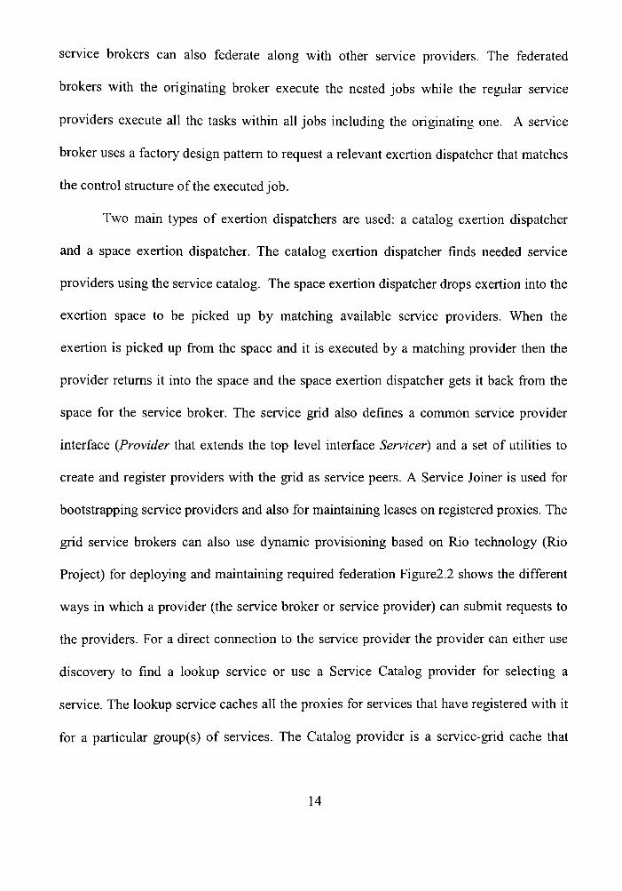
Project) for deploying and maintaining required federation Figure2.2 shows the different
ways in which a provider (the service broker or service provider) can submit requests to
the providers. For a direct connection to the service provider the provider can either use
discovery to find a lookup service or use a Service Catalog provider for selecting a
service. The lookup service caches all the proxies for services that have registered with it
for a particular group(s) of services. The Catalog provider is a service-grid cache that
14
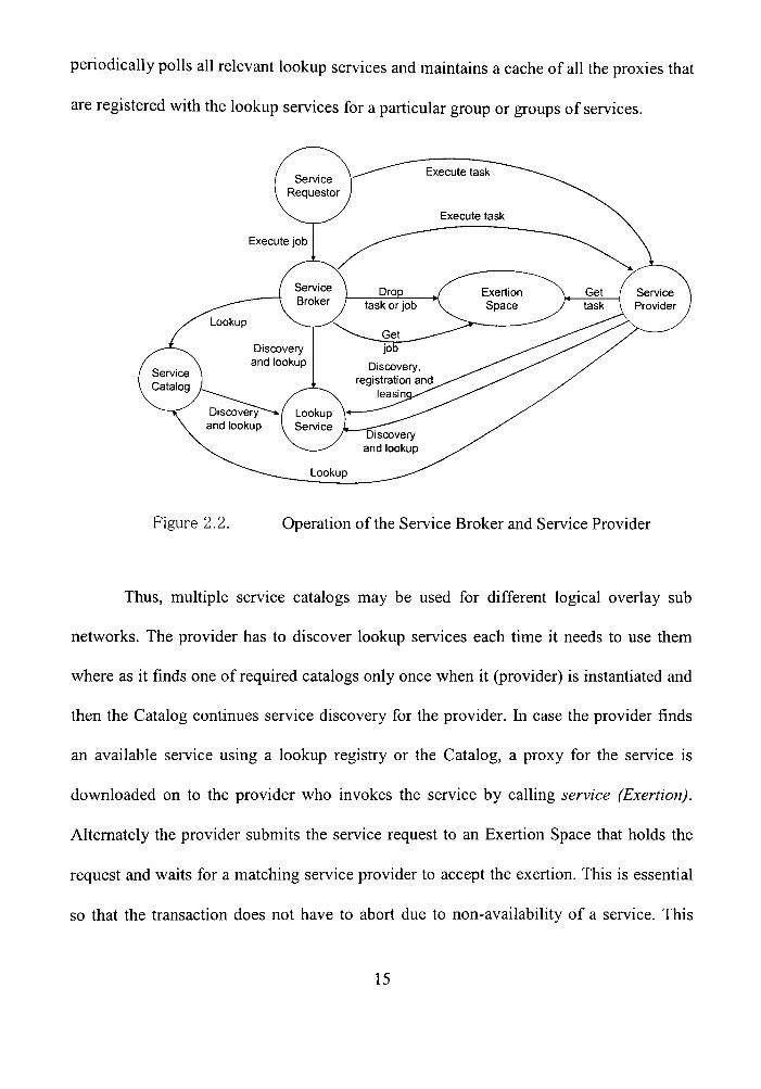
periodically polls all relevant lookup services and maintains a cache of all the proxies that
are registered with the lookup services for a particular group or groups of services.
Figure 2.2. Operation of the Service Broker and Service Provider
Thus, multiple service catalogs may be used for different logical overlay sub
networks. The provider has to discover lookup services each time it needs to use them
where as it finds one of required catalogs only once when it (provider) is instantiated and
then the Catalog continues service discovery for the provider. In case the provider finds
an available service using a lookup registry or the Catalog, a proxy for the service is
downloaded on to the provider who invokes the service by calling service (Exertion).
Alternately the provider submits the service request to an Exertion Space that holds the
request and waits for a matching service provider to accept the exertion. This is essential
so that the transaction does not have to abort due to non-availability of a service. This
15

also helps in better load balancing of the services since available providers will act at
their own pace to process the exertions in the space. A notification management
framework (Lapinski 2002) based on a notification provider allows federated providers
notify the service requestor on their collaborative actions. Additionally the File Store
provider (Sobolewski 2003) allows federated providers to share exertion input as well as
output data is a uniform service-oriented way.
2.4 SORCER Programming Paradigm
Service Oriented Programming (SOP) is a paradigm for distributed computing
built over Object Oriented Programming (OOP) paradigm emphasizing the point that
problems can be modeled in terms of services rather than objects. SOP differs from OOP
by focusing on what things can do whereas OOP focuses on what things are and how they
are constmcted. SOP defines set of core principles to maintain interoperability of services
over time. The core principles are
A service is an act of requesting a service (Exertion) operation from a service
provider.
> Service provider is defined as an independent self-sustaining entity performing a
specific network activity called exertion. The provider is a service, which
contractually defines a behavior.
r- The grid: a collection of service providers.
'^ A service provider mns a set of service-oriented routines (SOR). SOR's are
exposed to service requestors via a provider interface methods
16
^ Service Method: reference to SOR defined by m = (i, s), where i is a name of
provider interface, s is a name of method selector
> Service data: argument to SOR, called a context model, for short c
> Exertions are service-oriented programs and are of two types-Elementary and
Compound exertions. Elementary exertion analogous to network operation or
command - called task which is pair of ServiceMethod and context model,
i.e., (c, m), where m = (i, s)
a. Compound exertion is analogous to network program calledy'oZ? - aggregation of
tasks and other jobs
b. Job (c, m) follows semantics of SOP
c. c: a set of exertions along with control strategy to execute the job
d. m: a reference to a service provider that coordinates execution of job exertions,
called Service Broker or Jobber
A context model is the exertion's data stmcture and is based on the percept
calculus knowledge representation scheme (Sobolewski, 1993). It forms the essential
stmcture of the data being processed as specified by the exertion's interface and
operation. A context model of the exertion is represented as a tree-like stmcture of
context nodes (Zhao, 199) as shown in figure 2.3. It is represented by the ServiceContext
interface or alternatively can be represented in XML when used across heterogeneous
(non Java-based) programming environments. The actual data resides on a data node.
The context denotes an application domain namespace, and a context model is its context
with data nodes as leaf nodes appended to its context paths. A context path is a name for
17

a data in its leaf node. The leaf node might contain any object and in particular an object
that represents a file, for example a URL. A special container object called ServiceNode
acts as a wrapper that holds a reference to a remote document object available for
example from the File Store provider (Sobolewski, 2003).
(^ Name Space (Context)
Data Node Figure 2.3. Tree stmcture of context nodes
In the service grid environment two types of basic exertions are defined: tasks
dxidjobs. A task is the atomic exertion that is defined by its context model (data), and by
its method (operation). An exertion method defines a service provider (grid object) to be
bound to in mntime. This network object provides the business logic to be applied to the
exertion context model as specified in the exertion's method.
18
CHAPTER 3
J2ME AND JINI
3.1 Java 2 Micro Edition (J2ME)
3.1.1 Introduction
The Java 2 Micro Edition (J2ME) is a downsized version of standard Java edition
that provides a flexible environment to program and mn applications in consumer
electronic devices ranging from cell phones to high end PDA's, smart phones and setup
boxes. J2ME delivers the power of Java technology to consumer and embedded devices
and thus provides appropriate platform for wide variety of devices with different
processing capabilities. J2ME also provides the devices with flexible user interfaces,
robust security model and broad range of built in network protocols. Applications
developed conforming to J2ME specifications are written once and can be deployed on
numerous devices of same kind. It serves as persistent platform for all consumers and
embedded devices. [2]
3.1.2 Architecture
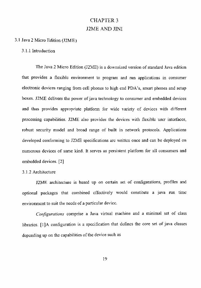
J2ME architecture is based up on certain set of configurations, profiles and
optional packages that combined effectively would constitute a Java mn time
environment to suit the needs of a particular device.
Configurations comprise a Java virtual machine and a minimal set of class
libraries. [1]A configuration is a specification that defines the core set of Java classes
depending up on the capabilities of the device such as
19

- Type and amount of memory avaUable
> Processor type and speed
> Tj^je of network connection available with the device
Optional Packages :
Java Virtual Machines
Host Operating System
Figure 3.4. J2ME Architecture
J2ME currently defines two sets of configurations depending up on the types of
devices being manufactured. They are
> Connected Limited Device Configuration (CLDC):
> CLDC is targeted to low end consumer devices which have typically 512ICB
memory like cell phones. It is closely associated with wireless Java and provides
mn time environment for mnning small Java applications called MIDlets.lt
contains less capable Java virtual machine often called as Kilo Virtual Machine
(KVM).
20
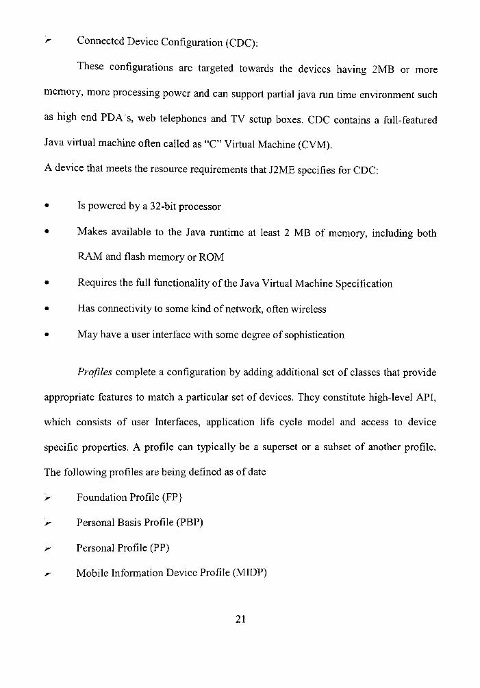
r- Connected Device Configuration (CDC):
These configurations are targeted towards the devices having 2MB or more
memory, more processing power and can support partial Java mn time environment such
as high end PDA's, web telephones and TV setup boxes. CDC contains a ftill-featured
Java virtual machine often called as "C" Virtual Machine (CVM).
A device that meets the resource requirements that J2ME specifies for CDC:
• Is powered by a 32-bit processor
• Makes available to the Java mntime at least 2 MB of memory, including both
RAM and flash memory or ROM
• Requires the full functionality of the Java Virtual Machine Specification
• Has connectivity to some kind of network, often wireless
• May have a user interface with some degree of sophistication
Profiles complete a configuration by adding additional set of classes that provide
appropriate features to match a particular set of devices. They constitute high-level API,
which consists of user Interfaces, application life cycle model and access to device
specific properties. A profile can typically be a superset or a subset of another profile.
The following profiles are being defined as of date
'r- Foundation Profile (FP}
K Personal Basis Profile (PBP)
K Personal Profile (PP)
r- Mobile Information Device Profile (MIDP)
21
For Example Personal Profile is built on top of CDC, foundation Profile and Personal
Basis Profile and the MIDP is built directly on top of CLDC.
Optional Packages are included to provide additional features to J2ME platform
for mobile devices. These features include Remote Method Invocation (RMI), database
connectivity, web services, and wireless messaging and multimedia facilities.
3.1.3 Benefits
Among the major benefits of Java technology that J2ME brings to the wireless
world are:
> The ability for carriers to utilize a wide range of manufacturers with the ability to
mn the same content
> Portability of code from one device to another
> Safe and secure network delivery, even over the Intemet
> A full mntime environment allows more interactive applications that do not use
excessive network bandwidth
> Off-line operation to allow users to interact with the service while in network
coverage or to save network costs by preparing material offline. [29]
I intend to continue my thesis research with Personal profile devices such as High
end PDA's to perform service oriented computing, which are capable of mnning
complete J2ME environment.
22

3.2 Jini Network Technology
3.2.1 Introduction
Jim is a set of Java classes and specifications that are platform independent and is built on
top of Java Technology as shown in the Figure 3 .2 and is platform independent too. The
Java Platform gives the Jini architecture a Universal type system, which is fully Object
oriented in nature.
w^m
i3i>AAtt ' i> .a-'fJ f * -ice .i t*-";;*!?*-!*^*? aftfe-ta-e^wv? i V
r -X i
Win NT-
Figure 3.5. Jini-Platform Independent
Jini inherits several properties from Java to support service-oriented architecture. They
are
Homogeneity
A single type system
Serialization
23

'' Code Downloading
> Safety and Security.
Jini Technology enables services to dynamically discover each other in the network and
also provides appropriate functionality to perform certain set of operation between the
services. For example, A Jini enabled printer can provide print service to the entire
network [3]. Jini services can be either hardware based or software based in nature. Jini
allows interaction between hardware and applications based on three basic features
>• Jini environment requires no user intervention when services are brought online
> Jini community is self-healing
> Consumers don't need prior knowledge of service implementation.
These features make it a dynamic environment where in service can enter or leave
the network at anytime and administration of services is pretty simple.Jini system is a
collection of clients and services communicating by means of Jini protocols. These
consist of applications written using java-programming language communicating with
Remote Method Invocation (RMI) mechanisms. A Jini system consists of the following
parts:
y A set of components that provides an infrastmcture for federating services in a
distributed system
'r- A programming model that supports and encourages the production of reliable
distributed services
> Services that can be made part of a federated Jini system and which offer
functionality to any other member of the federation
24

The unique qualities of Jini that makes this technology robust are code mobility,
design flexibility, self-configuration and self-healing networking. The components of the
Jini system can be segmented into three categories: infrastructure, programming model,
and services. The infrastmcture is the set of components that enables building a federated
Jini system, while the services are the entities within the federation. The programming
model is a set of interfaces that enables the constmction of reliable services, including
those that are part of the infrastmcture and those that join into the federation.
3.2.2 Goals of Jini
Jini was specifically designed for a service to be accessed by everyone in the
network. Once a service becomes available on the network any Jini enabled device can
access those services in type-safe and robust way. [12].The Goals of Jini architecture are
stated below:
>- Network Plug and work: When you plug a service on to the network it must be
visible to everyone and is available to everyone who wants to use it.
> Erase the Hardware/Software distinction: When you a want a service, the service
can come from anywhere and can be provided by any member (may be hardware
or just a piece of code) of the network.Jini as said earlier completely eliminates
distinction between hardware and software.
/- Enable Spontaneous Networking: Whenever services are plugged into the
network, they must be immediately available for the clients to dynamically
discover them and use them as they wish.
25

^ Promote Service Based Architecture: When applications are created for stand
alone purposes they can still be made available as services in the network by
certain deploying mechanisms. This enables service based architecture wherein all
applications can be considered as services for clients in the network. The easier it
is to make the service available on the network, more the number of services you
will find on the network.
> Simplicity: Jini services should be built on certain principles so that it would
provide a simple generic framework for services. Services should always be
designed in a way they are reusable and can be modified according to the users
needs.
3.2.3 Architecture
Jini Architecture provides an infrastmcture for defining, advertising and finding
services in a network. The Jini system extends the Java Application Environment from a
single virtual machine to a network of machines. The Java application environment
provides a good computing platform for distributed computing because both code and
data can move from machine to machine. The Jini architecture exploits these
characteristics of the Java application environment to simplify the constmction of a
distiibuted system. The Jini architecture adds mechanisms that allow fluidity of all
components in a distributed system, extending the easy movement of objects to the entire
networked system.[6].The environment provides buiU in security for dovynloaded code
from one machine to another.
26

Jini technology blurs the distinction between devices and software by
concentrating on the services that devices provide. Devices, whether they are pocket-
sized, consumer electronic items, desktop computers, or industiial machinery, provide
services that can be utiUzed by clients. These services can be unified by a Jini network.
Jini technology brings object-orientation to the network. Clients of a service need only
know the interface of that service vyritten in the Java programming language (Java
interface) to use it. The details of the service that implements the interface are hidden
from the client. [9]
> Services
The most important concept within the Jini architecture is that of a service. A
service is an entity that can be used by a person, a program, or another service. A service
may be a computation, storage, a communication channel to another user, a software
filter, a hardware device, or another user. Two examples of services are printing a
document and translating from one word-processor format to some other. Members of a
Jini system federate in order to share access to services. Services are defined via an
interface, and the implementation of a proxy supporting the interface that will be seen by
the service client will be uploaded into the lookup service by the service provider. This
implementation is then dovynloaded into the client as part of that client finding the
service. This service-specific implementation needs to be code vyritten in the Java
programming language to ensure portabiUty [13].PA Jini system consists of services that
can be collected together for the performance of a particular task. Services may make use
of other services, and a client of one service may itself be a service with clients of its
27
ovyn. The dynamic nature of a Jini system enables services to be added or withdrawn
from a federation at any time according to demand, need, or the changing requirements of
the workgroup using it.
Services in a Jini system communicate with each other by using a service
protocol, which is a set of interfaces vyritten in the Java programming language. The Jini
system defines these set of protocols for services to interact with each other.
> Lookup Service
Services are found and resolved by a lookup service. The lookup service is the
cenfral bootsfrapping mechanism for the system and provides the major point of contact
between the system and users of the system. A lookup service maps interfaces indicating
the functionality provided by a service to sets of objects that implement the service.
A service is added to a lookup service by a pair of protocols called discovery and
yo/w—first the service locates an appropriate lookup service (by using the discovery
protocol), and then it joins it (by using ihejoin protocol).
> Java Remote Method Invocation (RMI)
Java Remote Method Invocation (Java RMI) enables the programmer to create
distributed Java technology-based to Java technology-based applications, in which the
methods of remote Java objects can be invoked from other Java virtual machines*,
possibly on different hosts. RMI uses object serialization to marshal and unmarshal
parameters and does not tiuncate types, supporting tine object-oriented polymorphism.
Fundamentally, RMI is a Java-programming-language-enabled extension to
traditional remote procedure call mechanisms. RMI allows not only data to be passed
28

from object to object around the network but full objects, including code. Much of the
simplicity of the Jini system is enabled by this ability to move code around the network in
a form that is encapsulated as an object.
Communication between services can be accomplished by Remote Method
Invocation (RMI). The infrastmcture to support communication between services is not
itself a service that is discovered and used but is, rather, a part of the Jini technology
infrastructure. RMI provides mechanisms to find, activate, and garbage collect object
groups.
> Security
The design of the security model for Jini technology is built on the twin notions of
2i principal and an access control list. Jini services are accessed on behalf of some entity—
the principal—which generally fraces back to a particular user of the system. Services
themselves may request access to other services based on the identity of the object that
implements the service. The granting of access to a service depends on the contents of an
access confrol list that is associated with the object.
> Leasing
Access to services in the Jini system environment is lease based. A lease is a grant
of guaranteed access over a time period. Each lease is negotiated between the user of the
service and the provider of the service as part of the service protocol: A service which is
requested for some period is granted access for some period, presumably taking the
request period into account. If a lease is not renewed before it is freed-either because the
resource is no longer needed, the client or network fails, or the lease is not permitted to
29

be renewed~then both the user and the provider of the resource may conclude the
resource can be freed.
Leases are either exclusive or non-exclusive. Exclusive leases insure that no one
else may take a lease on the resource during the period of the lease; non-exclusive leases
allow multiple users to share a resource.
> Transactions
A series of operations, either within a single service or spanning multiple services,
can be defined as a transaction. The Jini Transaction interfaces supply a service protocol
needed to coordinate a two-phase commit. The implementation of a transaction is left up
to the service using the interfaces.
> Events
The Jini architecture supports distributed events. An object may allow other
objects to register interest in events in the object and receive a notification of the
occurrence of such an event. This enables distributed event-based programs to be vyritten
with a variety of reliabiUty and scalability guarantees.
3.2.4 Infrastmcture
The Jini technology infrastmcture defines the minimal Jini technology core. The
infrastmcture includes the following:
> A distributed security system, integrated into RMI, which extends the Java
platform's security model to the world of distiibuted systems
30
^ The discovery/join protocol, a service protocol that allows services (both
hardware and software) to discover, become part of, and advertise supplied
services to the other members of the federation
> The lookup service, which serves as a repository of services. Entries in the lookup
service are objects in the Java programming language; these objects can be
dovynloaded as part of a lookup operation and act as local proxies to the service
that placed the code into the lookup service
3.2.5 Programming model
Entries in the lookup service are leased, allowing the lookup service to reflect
accurately the set of currently available services. When services join or leave a lookup
service, events are signaled, and objects that have registered interest in such events get
notifications when new services become available or old services cease to be active. The
programming model rests on the ability to move code, which is supported by the base
infrastmcture.
Both the infrastmctiu-e and the services that use that infrastmcture are
computational entities that exist in the physical environment of the Jini system. Services
also constitute a set of interfaces, which define communication protocols that can be used
by the services and the infrastioicture to communicate between themselves.
These interfaces, taken together, make up the distiibuted extension of the standard
Java programming language model that constitutes the Jini programming model. Among
the interfaces that make up the Jini programming model are the following:
31

> The leasing interface, which defines a way of allocating and freeing resources
using a renewable, duration-based model
> The event and notification interface, which is an extension of the event model
used by Java Beans components to the distributed environment that enables event-
based communication between Jini services
> The transaction interfaces, which enable entities to cooperate in such a way that
either all of the changes made to the group occur atomically or none of them
occur
3.2.6 Services
Services are objects written in Java programming language. A service has an
interface which defines the operations that can be requested of that service. Some of these
interfaces are intended to be used by programs, while others are intended to be mn by the
receiver so that the service can interact with a user. The type of the service determines the
interfaces that make up that service and also define the set of methods that can be used to
access the service. A single service may be implemented by using other services.
Services form the interactive basis for a Jini system, both at the programming and user
interface levels
> Discovery and Lookup Protocols
The heart of the Jini system is a trio of protocols called discovery, join, and
lookup. A pair of these protocols~discovery/join~occurs when a device is plugged in.
Discovery occurs when a service is looking for a lookup service with which to register.
Join occurs when a service has located a lookup service and wishes to join it. Lookup
32

occurs when a client or user needs to locate and invoke a service described by its
interface type (written in the Java programming language) and possibly, other attiibutes.
The following diagram outlines the discovery process.
Service provider seel<s a lookup service
Lookup Service
Service Provider
Senfioe Objed
Service Anribirtes
Figure 3.6. Discovery
Discovery/Join is the process of adding a service to a Jini system. A service provider is
the originator of the service—a device or software, for example. First, the service provider
locates a lookup service by multicasting a request on the local network for any lookup
services to identify themselves (discovery. Figure 3.3). Then, a service object for the
service is loaded into the lookup service (join. Figure 3.4). This service object contains
the Java programming language interface for the service including the methods that users
and applications will invoke to execute the service, along with any other descriptive
attributes.
33

A service provider registers a Service Object and Its Service
AttribLTtes with the lool<up service
Lookup Service
Service Objecl
Senicse AUrihulBs
Service Provider
Service Object
Service AllribulBS
Figure 3.7. Join
Services must be able to find a lookup service; however, a service may delegate the task
of finding a lookup service to a third party. The service is now ready to be looked up and
used, as shown in the following diagram (Figure 3.5).
A client requests a service by Java type and, perhaps, other
service attributes. A copy of the service object is moved to the
client and used by the client to tall<tothe service
Lookup Service
Service Ohjecl
Service Attributes
^^in^
Client
Service 0 bject
Service Provider
Figtire 3.8. Lookup
A client locates an appropriate service by its type-that is, by its interface written
in the Java programming language-along with descriptive attributes which are used in a
user interface for the lookup service. The service object is loaded into the client.
The final stage is to invoke the service, as shown in the following diagram
(Figure 3.6). The service object's methods may implement a private protocol between
34

itself and the original service provider. Different implementations of the same service
interface can use completely different interaction protocols.
The ability to move objects and code from the service provider to the lookup
service and from there to the client of the service gives the service provider great freedom
in the communication pattems between the service and its clients. This code movement
also ensiures that the service object held by the client and the service for which it is a
proxy are always synchronized, because the service object is supplied by the service
itself The client only knows that it is dealing with an implementation of an interface
vyritten in the Java programming language, so the code that implements the interface can
do whatever is needed to provide the service. Because this code came originally from the
service itself, the code can take advantage of implementation details of the service knovyn
only to the code.
The client interacts directly with the Service Provider
via the Service Object
Lookup Service
Servicx 0 bject
Service Attributes
Client
Service Object fm 1^
Service Provider
Figure 3.9. Service Invocation
The client interacts with a service via a set of interfaces written in the Java
programming language. These interfaces define the set of methods that can be used to
interact with the service. Programmatic interfaces are identified by the type system of the
35

Java programming language, and services can be found in a lookup service by asking for
those that support a particular interface. Finding a service this way ensures that the
program looking for the service will know how to use that service, because that use is
defined by the set of methods that are defined by the type.
Programmatic interfaces may be implemented either as RMI references to the
remote object that implements the service, as a local computation that provide all of the
service locally, or as some combination. Such combinations, called smart proxies,
implement some of the functions of a service locally and the remainder through remote
calls to a centralized implementation of the service. A user interface can also be stored in
the lookup service as an attribute of a registered service. A user interface stored in the
lookup service by a Jini service is an implementation that allows the service to be directly
manipulated by a user of the system. In effect, a user interface for a service is a
specialized form of the service interface that enables a program, such as a browser, to
step out of the way and let the human user interact directly with a service. In situations
where no lookup service can be found, a client could use a technique called peer lookup
instead. In such situations, the client can send out the same identification packet used by
a lookup service to request service providers to register. Service providers will then
attempt to register with the client as though it were a lookup service. The client can select
those services it needs from the regisfration requests it receives in response and drop or
refuse the rest.
36

CHAPTER 4
JINI SURROGATE ARCHITECTURE
4.1 Infroduction
The surrogate architecture is buiU upon the Java™ platform and Jini network
technology (Jini technology). By using the surrogate architecture, devices that could not
easily take advantage of Jini technology may now become part of a network of Jini
technology-enabled services and/or devices (Jini network).ThQ surrogate architecture
defines how a set of related technologies provide a framework for surrogates to act on
behalf of the devices which are incapable of utilizing Jini Technology directly.
4.2 Requirements
Jini technology is not just providing services. To be part of a system of Jini
technology-enabled services and/or devices, a service must also be able to participate in
the Jini discovery protocol and register itself into the local Jini lookup service. In order
for a hardware or software component to join in a network of Jini™^ technology-enabled
services (Jini network), it must satisfy several critical requirements:
It must be able to participate in the Jini discovery and join protocols, and it must
be able to download and execute classes vyritten in the Java™^ programming language. In
addition, it may need the ability to export classes written in the Java programming
language so that they are available for dovynloading to a remote entity. For many
hardware or software components, these requirements are not difficult to meet; however,
there is a category of components that, for one reason or another, cannot satisfy one or
more of the requirements and therefore cannot participate directiy in a Jini network. The
37

•TM Jini Technology Surrogate Architecture Specification addresses this problem by
defining a means by which these components, with the aid of a third party, can participate
in a Jini network while still maintaining the plug-and-work model of Jini technology. [10]
In order to fully understand the requirements. Figure 4.1 gives a general
description of a fully Jini enabled device that can support all functionalities for
registering and discovering services. Such a device would be able to make full use of Jini
technology and Java technology, uploading code that is used to communicate with the
device and downloading code that might be needed for the service provided by the device
[13].
Service CLient Service Provider
Hardware ImpIemerLtation
A Pri'vate , Protocol
Tai.'a VM
(Conimunication via RMI protocol)
Figure 4.10. Jini Enabled device
Here both the service provider and service client shown are fiiUy Jini enabled to
provide efficient servicing. The Service provider has its ovyn JVM running so as to
38
register the service on to the network. A client can now discover the service and
dovynload the proxy from the look service and can fully utilize the service.
As stated, for devices to fully utilize tiie power of Jini they need to have sufficient
amount of memory and processing power to provide service and lookup services to and
from the network. Since all the mobile devices that mn with J2ME don't have sufficient
memory to access Jini services directly they are unable to participate in the Jini network.
To provide a Jini service, a device needs to perform register the service to the Jini
Lookup service. Similarly to access a Jini service a client/device needs to download a
proxy which gets executed on its JVM.There arise situations for mobile clients where
they caimot accommodate objects directly on the JVM as it might exhaust all the limited
resources. Such devices though can provide important services but are restricted to mn
programs written in Java Programming language. Therefore Jini clients and services
cannot run directly on these devices.
Jini has infroduced device architecture using which a non-Jini device can act as
service providers and also as clients in the network as shown in the Figure 4.2.
39

Service Client
HetsTOik
Netm>ik Piojy
Java VM
(CocnrtiuniQtiocivia RMI protocol)
pnvatE putDcols
dev 1
dev 2
dev 3
Service Pnovideis
Figure 4.11. Device Architecture for non-Jini devices
Here the devices create a Network Proxy for themselves which is present on some
device (host) on the network acting on behalf of the device performing the required
device services. Since the device JVM cannot have full Jini support, the proxy for the
device uses the JVM of the current host and support full Jini functionality for the device.
The Jini surrogate architecture uses the device architecture and lowers the
requirements that a device needs to participate in the Jini network. The Jini architecture
demands that objects be mobile; the surrogate architectiu-e provides a place for those
objects to exist other than the device itself The following clearly states the requirements
of surrogate architecture
> Device Type Independence The surrogate architecture must be able to support a
wide range of hardware and software components with different capabilities.
40
> Network Type Independence - The surrogate architecture must be able to
accommodate a diverse range of coimectivity technologies. Network type
independence includes support for different protocols simuUaneously on the same
physical transport.
> Preserve Plug-and-Work - The surrogate architecture must preserve the plug-and-
work model of Jini technology. The Jini architecture includes the concepts of
discovery, code dovynloading, and leasing of distributed.
4.3 Terms and Definitions
To clearly understand the complete nature of surrogate architecture it is necessary
to define the terms used for building the framework. The following defines the
components used in this surrogate architecture framework.
> A device refers to a hardware or software component that is not capable of
directly participating in a Jini network.
> A surrogate is an object that represents a device. The implementation of the
object may be a collection of Java software components and other resources.
> A host-capable machine is a system that allows the downloading of code, can run
a surrogate, is part of a Jini network, and is accessible to the entity offering the
surrogate.
> The surrogate host is a framework that resides on the host-capable machine and
provides a Java application environment for executing the components of the
surrogate architecture. In addition to providing computational resources, an
41

execution envirormient, and life-cycle management, the surrogate host may also
provide other host resources to assist the components in the architecture.
> An export server is a component or set of components, that is part of, the
surrogate host that provides the means by which surrogate resources are exported
so that they are available for dovynloading to remote entities. The exports of
resources, particularly class files, are necessary for many Jini technology
operations.
> Interconnect is the logical and physical connection between the surrogate host
and a device. There may be more than one interconnect defined for a physical
cotmection. It is also possible for interconnect to be on the same physical
connection that forms the Jini network.
> A interconnect protocol includes the interconnect-specific mechanisms for
discovery, retrieval of the surrogate, and live ness.
4.4 Architecture
The foremost assumption of surrogate architecture is that there exists a host
capable machine that is cormected to one or more interconnects and Jini network. The
Host capable machine has all the resources to execute code written in java programming
language on behalf of the device.
42

Jini Network
Host-capabte Machine
Surrogate Host
Host Resources
Interconnect Device
Figure 4.12. Initial state of Surrogate Architecture
The Jini Network and Intercormect are shown in two separate paths but however
they can coexist in same path if necessary. The Initial state of the surrogate architecture is
shovyn in the Figure 4.3. Here the Surrogate host monitors the state of the Interconnect.
There can be more than on e Intercormect attached to the surrogate host and the surrogate
host is capable of monitoring all the Interconnects attached to it.
4.4.2 Discovery and Surrogate Loading
The surrogate host is responsible for implementing the interconnect protocol for a
specific intercormect. The first part of the intercoimect protocol that comes into play is
discovery. Discovery is defined, as the protocol that is used by the device and surrogate
host to find each other. A particular discovery protocol is intercormect specific and may
be very different from any other intercotmects discovery protocol, depending on the
capabilities of intercormect and the device.
43
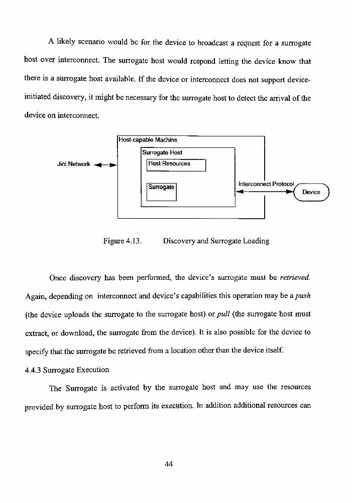
A likely scenario would be for the device to broadcast a request for a surrogate
host over interconnect. The surrogate host would respond letting the device know that
there is a surrogate host available. If the device or intercormect does not support device-
initiated discovery, it might be necessary for the surrogate host to detect the arrival of the
device on intercormect.
Jini Network
Host-capaWe Machine
Surrogate Host
Host Resources
Surrogate Interconnect Protocol - * • Y—"^
•f Device )
Figure 4.13. Discovery and Surrogate Loading
Once discovery has been performed, the device's surrogate must be retrieved.
Again, depending on intercormect and device's capabilities this operation may be a push
(the device uploads the surrogate to the surrogate host) or pull (the surrogate host must
extract, or download, the surrogate from the device). It is also possible for the device to
specify that the surrogate be retrieved from a location other than the device itself
4.4.3 Surrogate Execution
The Surrogate is activated by the surrogate host and may use the resources
provided by surrogate host to perform its execution. In addition additional resources can
44
also be exported by export server into the surrogate host to perform execution of the
surrogate.
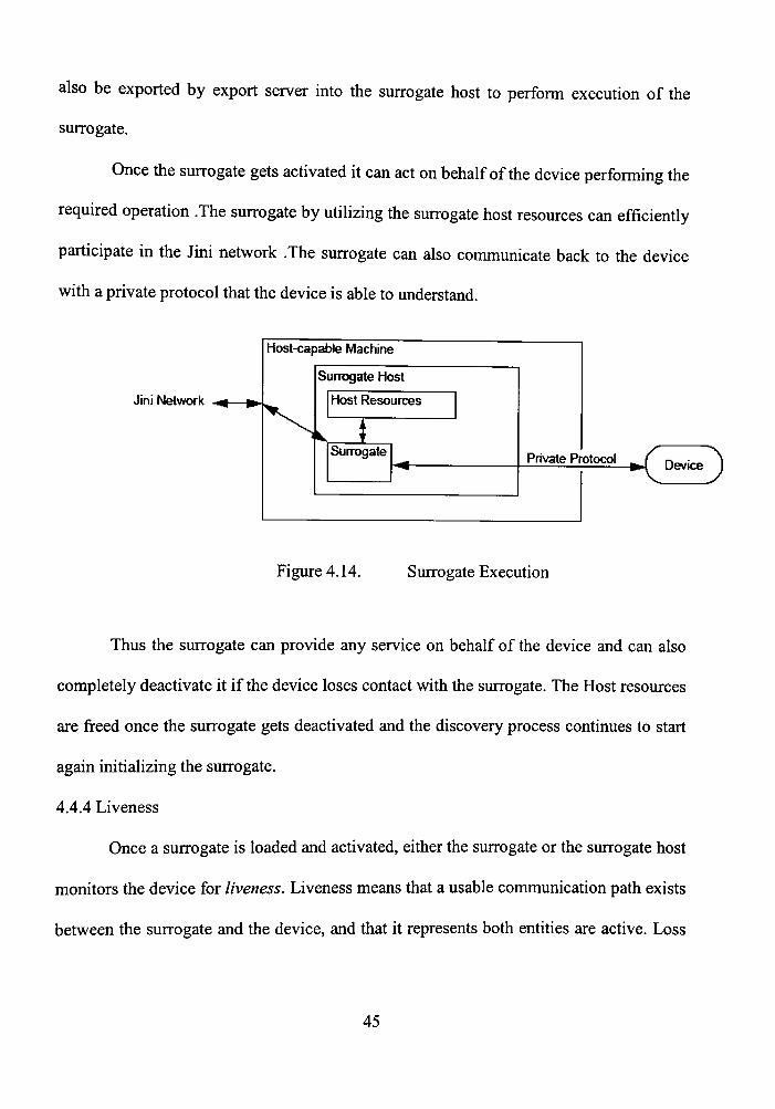
Once the surrogate gets activated it can act on behalf of the device performing the
required operation .The surrogate by utilizing the surrogate host resources can efficiently
participate in the Jini network .The surrogate can also communicate back to the device
with a private protocol that the device is able to understand.
Jini Network
Host-capable Machine
Surrogate Host
Host Resources
* Surrogate
-^ Private Protocol _ ^
S Device J
Figure 4.14. Surrogate Execution
Thus the surrogate can provide any service on behalf of the device and can also
completely deactivate it if the device loses contact with the surrogate. The Host resources
are freed once the surrogate gets deactivated and the discovery process continues to start
again initializing the surrogate.
4.4.4 Liveness
Once a surrogate is loaded and activated, either the surrogate or the surrogate host
monitors the device for liveness. Liveness means that a usable communication path exists
between the surrogate and the device, and that it represents both entities are active. Loss
45

of the conimunication path could be the result of either normal or error conditions in the
surrogate host, the surrogate, interconnect, or the device. If the device is no longer
reachable, because of interconnect or device failure, or because the device has been
disconnected or shut down, the surrogate that it represents must be deactivated so that the
resources allocated to it by the surrogate host can be reclaimed. Also, the surrogate
should release any remote resources that it holds, such as lookup service registrations.
The device must be able to determine that it is no longer in contact with the surrogate,
possibly because of an interconnect failure, a fault in the surrogate, or a surrogate host
failure or shut dovyn. In any one of these events, the device should resume discovery (if it
supports device-initiated discovery) or otherwise prepare to upload a new surrogate.
4.5 Intercormect
Sim Microsystems has come up with certain set of specifications to define
interconnects that establish communication between surrogate host and the device. Some
of the Interconnects specified for the surrogates by Sun Microsystems are IP
Interconnect, Smart card Intercormect, USB Intercormect and Interconnect for lEEE-
1394[ 15].Devices depending up on their capability can use any one of these interconnects
to communicate with the surrogate host. These intercoimects also define device specific
protocol mechanisms for surrogate discovery, retrieval and aliveness.
4.5.1 Requirements
A device or surrogate host that uses the surrogate architecture for a given inter
cormect must comply with both an intercormect specification for that inter-coimect and
the Jini"™^ Technology Surrogate Architecture Specification [16]. In order to define the
46
components for a particular inter-cormect either the existing protocols can be used or new
protocols can be defined conforming to the interconnect specifications. The following are
the requirements that define the protocols for a particular inter-connect.
^ Discovery
The mechanism by which a device and a surrogate host locate one another must
be specified. This mechanism is necessary and may consist of hardware or software
protocols, or other means that are appropriate to the specific interconnect to maintain the
plug-and-work model. The discovery mechanism must define a way in which a device,
when attached to interconnect, can either: announce their presences such that a surrogate
host can detect it, or detect a surrogate host on that intercormect. Likewise, the
mechanism must define a way that a surrogate host attaching to interconnect can
armounce its presence or, through some other means, find all of the devices on
intercoimect. The discovery mechanisms must operate without requiring administration
of the surrogate host. This means that no external action should be required in order for
the surrogate host to recognize a new device on interconnect that it supports.
> Surrogate Retrieval
All interconnect specifications must define how surrogate components are
retrieved. The sirrrogate retrieval portion of the interconnect specification must describe a
mechanism that is device independent. Device independence in this context means that
the surrogate host does not need prior knowledge of any specific device that implements
the intercormect specification. This restriction is important in order to introduce a new
device type for an existing inter-connect, without requiring changes to the surrogate host.
47
^ Liveness
All interconnect specifications must specify the mechanism for determining
whether the device is still reachable on intercormect. This requirement is necessary to
maintain the surrogate's residency in the surrogate host and to allow for the deactivation
of the surrogate if the device is no longer functioning, is no longer attached to the
interconnect, or if the interconnect has failed. This mechanism is also necessary to allow
the release of any leased resources held by the surrogate. Liveness also includes the
ability of the device to determine if it is still in contact with its surrogate. It may be the
responsibility of the surrogate host or the surrogate to determine liveness.
4.6 IP Interconnect
4.6.1 Overview
Intemet Protocol (IP) provides an easier and safer way to establish
communication in networking for both WLAN and LAN communications. The Intemet
protocols consist of a suite of communication protocols, of which the two best known are
the Transmission Control Protocol (TCP) and the Intemet Protocol (IP). The hitemet
protocol suite not only includes lower-layer protocols (such as TCP and IP), but it also
specifies common applications such as electronic mail, terminal emulation, and file
ti-ansfer [14].
Jini has taken full advantage of this protocol and has defined set of specifications
to establish efficient communication between the surrogate host and the device. IP can be
implemented for various physical media such as Ethernet or wireless networks. The
48
protocols defined by this specification are applicable to any physical layer that supports
IP [15]. The IP interconnect protocol specifies:
^ Discovery -Discovery is a process by which a device and surrogate host discovers
each other. Both the device and the surrogate host must have multicast capability
to inform each other of their existence.
> Retrieval - Retrieval is a process through which the surrogate is retrieved. The IP
intercormect protocol allows for the use of various data transfer mechanisms for
retrieval of the surrogate, including File Transfer Protocol (FTP), Trivial File
Transfer Protocol (TFTP), UDP, TCP, and Hypertext Transfer Protocol (HTTP).
> Liveness - How the device and the surrogate host communicate that the surrogate
is fimctioning and the device for the surrogate is still reachable on intercormect.
Liveness must be implemented by using a protocol between the surrogate and the
device. The protocol used to communicate liveness is not mandated by this
specification.
4.6.2 Discovery protocols
The IP Intercoimect protocol defines the way surrogate host and the device
discovers each other. It also states how the surrogate host retrieves the surrogate from the
device, mns it and maintains the state of surrogate till it gets deactivated. Discovery is the
processes by which the device and surrogate host find each other over interconnect. A
surrogate host and a device must support the multicast host annoimcement and multicast
host request protocols:
49
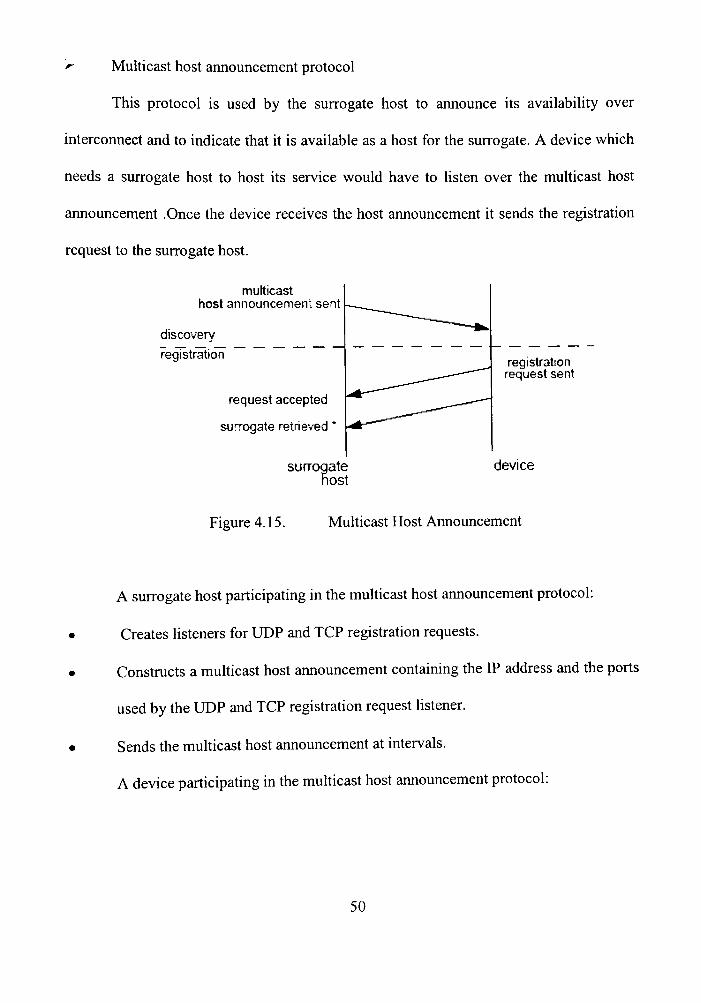
r- MuUicast host announcement protocol
This protocol is used by the surrogate host to announce its availability over
interconnect and to indicate that it is available as a host for the surrogate. A device which
needs a surrogate host to host its service would have to listen over the multicast host
announcement .Once the device receives the host announcement it sends the registration
request to the surrogate host.
multicast host announcement sent
discovery
registration
request accepted
surrogate retrieved
surroqate host
registration request sent
device
Figure 4.15. Multicast Host Announcement
A surrogate host participating in the multicast host announcement protocol:
Creates listeners for UDP and TCP registration requests.
Constmcts a multicast host announcement containing the IP address and the ports
used by the UDP and TCP registration request listener.
Sends the multicast host announcement at intervals.
A device participating in the multicast host announcement protocol:
50

• Creates a listener for multicast host armouncements
• Makes a registration request to the host using the registration request protocol
upon receiving a unicast host response.
The surrogate host must send a series of no more then ten multicast host
announcements when it is first initialized and then send an additional multicast host
announcement at intervals. The length of the interval is not mandated, but 30 seconds is
recommended and 120 seconds should be the maximum. A surrogate host that is unable
to accept registration requests must cease sending multicast host announcements. If the
host is later able to accept registration requests, the host must resume sending multicast
host announcements. A device might receive more than one multicast host announcement
from the same surrogate host. It might also receive a multicast host announcement from
more than one surrogate host. A device listens for multicast host announcements when it
needs to locate a surrogate host. While a device has a relationship with an active
surrogate, it may stop listening for multicast host announcements, but it must resume
listening if it loses its connection with the surrogate.
> Multicast host request protocol
A device uses this protocol to discover a surrogate host over the interconnect A
device that needs a surrogate host sends a multicast host request. The surrogate host,
which is listening on the multicast port for the request, responds to the device with a
unicast host response. The device uses the address in the unicast host response to
generate a registration request for that host to serve as host for its surrogate. If the
surrogate host accepts the request, the surrogate is retrieved.
51

unicast host response sent
discovery
registration
multicast host request sent
request accepted
surrogate retrieved
surrogate host
registration request sent
device
Figure 4.16. Multicast Host Request protocol
A device participating in the multicast host request protocol:
Creates a unicast UDP listener to receive unicast host responses.
Constmcts a multicast host request that contains the IP address and port of the
unicast host response listener.
Sends a series of multicast host requests.
Makes a registration request to the host using the registration request protocol
upon receiving a unicast host response
A surrogate host participating in the multicast host request protocol:
52
• Creates listeners for UDP and TCP registration requests.
• Creates a listener for multicast host requests on the host request multicast group.
• Constmcts a unicast host response containing the IP address and the ports used
by the UDP and TCP registration request listeners upon receiving a multicast host
request.
• Sends the unicast host response to the device using the IP address and port
contained in the multicast host request.
When a device enters interconnect, it should pause a random amount of time (up
to 15 seconds is reasonable). This delay reduces the likelihood of a packet storm
occurring if power is restored to an interconnect segment that houses a large number of
devices. After pausing, the device should send no more than ten multicast host requests at
periodic intervals. The interval at which requests are sent is not specified, though an
interval of five seconds is recommended. A device might receive more than one unicast
host response from the same surrogate host. It might also receive a unicast host response
from more than one surrogate host.
A surrogate host that is unable to accept registration requests should stop listening
for multicast host requests. If the host stops listening for registration requests and is later
able to accept registration requests, the host must resume listening for multicast host
requests. Once a device has a relationship with an active surrogate, it should stop sending
multicast host requests.
53

4.6.3 Discovery using IP Interconnect
The discovery process begins with the surrogate host, which periodically sends IP
multicast packets containing the registration request address through the multicast host
announcement protocol and thus aimounces its presence on the IP Interconnect. When a
device establishes contact with interconnect, it initializes the multicast host request
protocol which mns concurrently with the host announcement protocol. The device sends
periodic signals containing the host response address.
Mbst-c^able machine
Surrogotc Nos'i^
Host Resources
I n tcrco rnec;
-p) W.ulticost Hosi'
Anncjrccrt icnts
im
X h-^^ (((|;
mr
— Device
Jini Network V Mul+'cci-t Hcst fJcauei-ts.
Untco.s+ Most Rcsporjc
Figure 4.17. Discovery using IP Interconnect
Now either the surrogate host or the device can initiate discovery depending up on
the order in which they appear over the IP Interconnect. When the surrogate host receives
a request from the device, it sends the registration request address to the host response
address from the device. Once the device gets response from the host it can register the
surrogate through certain device specific mechanisms.
54

4.6.4 Surrogate Retrieval
Retrieval of the surrogate is accomplished using the registration request protocol.
The registration request protocol defines the messages and mechanism used by the device
to request that a surrogate host load the device's surrogate JAR (Java Archive) file. The
device makes this request by sending a registration message to the surrogate host. The
registration message contains either the surrogate itself, or the location of the surrogate
along with the protocol to use to retrieve the surrogate. The registration may also contain
device-specific initiaUzation data.
> Registration Request Protocol
Once a device has obtained the IP address and port of the surrogate host, either
through one of the discovery protocols or from configuration information, the device may
send a registration request to that host in one of two ways. The device may send the
request as a unicast UDP message or it may open a TCP connection to the surrogate host
and send the message to the host via that connection.
> A device making a registration request:
• Constmcts a registration request
If the registration request is to be sent as a UDP packet, sends the registration request to
the host using the IP address and UDP listener port of the surrogate host. If the
registration request is to be sent over a TCP socket, opens a TCP socket on the IP address
and TCP listener port of the surrogate host and writes the registration request to that
socket.
55

• Waits for confirmation from the device's surrogate that the surrogate has been
activated by the host.
> A surrogate host accepting a registration request:
• Creates a listener for UDP registration requests
• Creates a listener for TCP connections
The surrogate host may use different port numbers for the UDP and TCP listeners.
These port numbers, along with the surrogate host's IP address, are provided to the
device in the multicast host announcement and unicast host response. A device
attempting to register with a surrogate host should wait some amount of time for its
surrogate to be activated before attempting to register again. If the surrogate host remains
unresponsive, the device should attempt to discover another host.
A device may attempt to register with more then one surrogate host. It is the
responsibility of the surrogate and the device to coordinate multiple registrations. If a
surrogate host receives more than one registration request from the same device, it must
attempt to honor all of the registrations. It is the responsibility of the surrogate and the
device to determine if duplicate registrations have been made, and to then deactivate any
unnecessary surrogates. If a registration request is made through a TCP socket
connection, the surrogate host may close that connection at any time after the surrogate
host has received the registration request. A surrogate host that is unable to accept
registrations should stop listening for registration requests (both UDP and TCP). If the
surrogate host stops listening for registration requests and is later able to accept
registrations, it can resume listening for registration requests.
56

4.6.5 Registration using IP Interconnect
As soon as the surrogate host and device discover each other the IP Interconnect,
the device registers its surrogate to the host using the registration request protocol. The
devices using the registration request address and using either TCP or UDP port registers
the surrogate to the host. The choice of choosing either TCP or UDP depends up on the
device.
bie machme
Surrogate Host
Host fitisourccs
Surrogote
t
'i
\
I ln tc -cor rect I
Jini Network
Device
UiKcost registro*ior
rc<jucs-t (URL to the
surrogate j or f i !c)
Figure 4.18. Registration using IP Interconnect
The device sends the unicast registration request directly to the surrogate host's
registration request address. The surrogate can either be bytes of a JAR file or can point
to any URL location on the network. The surrogate host then reads the surrogate file and
then activates it separating it from other surrogates mnning inside the host.
4.6.6 Surrogate Reachability
^ Device presence
Once the surrogate is loaded and activated it must continually monitor the device
for its presence on the network. This process is accomplished using the interconnect
mechanisms specific to the surrogate host and the device. If the device can't be reached.
57
then the surrogate must be deactivated and all the resources held by the surrogate host
must be freed and the remote resources must be released.
^ Surrogate presence
The surrogate must periodically inform the device that its still active inside tiie
surrogate host. If the device is not able to receive confirmation from the surrogate it must
resume host discovery and restart the surrogate.
4.7 Surrogate Packaging
The surrogates that act on the behalf of the device are packaged in separate JAR files.
The JAR file should include all the Jini class files necessary for the surrogate to join the
Jini network. The following are mandatory to occur inside a JAR file.
> A manifest file containing at least the following elements:
• A single, mandatory Surrogate-Class header specifying the name of the surrogate
class. For example:
Surrogate-Class: com.acme.surrogate.mySurrogate
• An optional Surrogate-Code base header, specifying the resources of the surrogate
code base.
Surrogate-Code base: resource [resource]
> A class that implements the Surrogate interface, as well as any other resources
that implement the surrogate. These resources may be classes written in the Java
programming language, as well as any other data such as HTML files or icons.
58

The manifest of the surrogate JAR file must not contain a Class-Path header. If
this header is present the surrogate JAR file is discarded. The retrieval of surrogate JAR
file by the surrogate host is defined by an interconnect specification.
4.8 Madison Surrogate Host
Sun Microsystems has introduced the Madison Surrogate host conforming to both
Jini Technology Surrogate Architecture Specification and the Jini™ Technology IP
Interconnect Specification for non-Jini devices to join the Jini network. Madison
surrogate is designed using Java 2 SDK, Standard Edition, vl.2.2 or greater and Jini
Technology Starter Kit, yl.2.1_001.
4.8.1 Design
This section provides a detailed design of Madison surrogate architecture
specifying the modules and interfaces defined using the Jini Surrogate architecture
specification. This also provides the concept behind module interactions and also
describes the process of surrogate registration and activation.
4.8.2 Modules
Madison consists of three main modules, which are Export server Module, Host
Module and Adapter module. These modules interact with each other using five
interfaces with the start up process being performed by the HostStarter class. [19] The
Module interactions using the interfaces are shown in the figure. The arrows indicate the
direction of method invocation from callers to callees. For example, there is an arrow
labeled in Figure 4.10 as AdapterContext, pointing from the adapter module to the host
module.
59

HostStarter
ResourceResolver «<
Host Module
AdapterContext
(SurrogatelD)
(SurrogatelD) Export Server Module
ExportServer
Adapter
Adapter Module
Figure 4.19. Module interaction in Madison
This arrow indicates that the adapter module has a reference to an object that is
provided by the host module, which implements the AdapterContext interface, and whose
methods can be invoked by the adapter module. The SurrogatelD, enclosed in brackets
and placed in between arrows that point in both directions, is used to denote that objects
implementing the SurrogatelD interface are passed as parameters of methods calls in both
directions.
The HostStarter does the following in sequence:
> Instantiates the export server
> Instantiates the host
> Instantiates the adapter
> Add the adapter to the host's managed adapter list
60
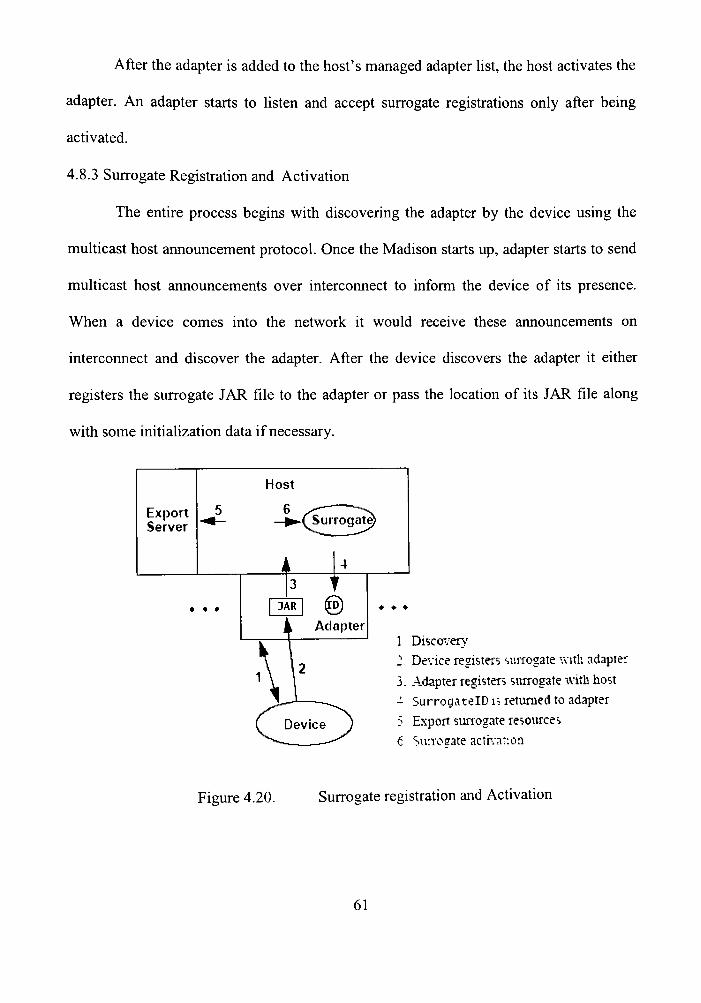
After the adapter is added to the host's managed adapter list, the host activates the
adapter. An adapter starts to listen and accept surrogate registrations only after being
activated.
4.8.3 Surrogate Registration and Activation
The entire process begins with discovering the adapter by the device using the
multicast host announcement protocol. Once the Madison starts up, adapter starts to send
multicast host armouncements over interconnect to inform the device of its presence.
When a device comes into the network it would receive these announcements on
interconnect and discover the adapter. After the device discovers the adapter it either
registers the surrogate JAR file to the adapter or pass the location of its JAR file along
with some initiaUzation data if necessary.
1 Discoverv' J Device registers iuirogate with adapter 3. Adapter registers surrogate with host -• SurrogatelD is returned to adapter
Export sunogate resources 6 Surrosate activanoii
Figure 4.20. Surrogate registration and Activation
61
The location can point to any URL on the network or can be downloaded from the
same device. Once the adapter receives the registration, the adapter calls the register
method of its AdapterContext to register the surrogate JAR file and an interconnect
context to the host. The host passes the intercoimect context to the surrogate when
activating it. The register method retums a SurrogatelD to the adapter immediately,
without waiting for the surrogate to be activated. The SurrogatelD uniquely identifies the
surrogate and can be used by the adapter to refer to the surrogate during the adapter's
subsequent interactions with the host. The host reads the manifest of the surrogate JAR
file and exports the required resources using the export server.
After all these process are completed the Host activates the surrogate which then
becomes a part of Jini network. Once a surrogate is activated, it may join a federation of
Jini technology-enabled services and/or devices by using the Jini technology packages
and the TCP/IP facilities provided by the host.
4.8.4 Surrogate Deactivation
Surrogate deactivation can be initiated from three sources:
• The surrogate itself, by calling HostContext.canceIActivation()
• The host, by calling Surrogate.deactiyate()
• The adapter, by calling AdapterContext.terminateSurrogate(SurrogatelD)
After the host deactivates its surrogate, the loading adapter will be notified via
Adapter.surrogateDeactivated (SurrogatelD) or DeactivationListener.deactivated (),
respectively.
62

4.8.5 Multiple surrogates
Madison was designed in such a way that it can support multiple surrogates in it.
Whenever devices enter a network and starts looking for a host, Madison would send the
host announcement to all devices. Once the devices receive the announcement they can
continue the process of surrogate registration as defined earlier. Madison mns a separate
thread group for each and every surrogate it supports. A surrogate can only access
information about its own thread group, not about other thread groups. Any uncaught
exception from a surrogate thread will be caught at its group level, which will result in its
deactivation.
Figure 4.21. Multiple Surrogate Threads
4.8.6 MuUiple Adapters
Madison also has capability to support multiple adapters for different devices. The
adapter for the specific device is designed and then can be added on to the host by
explicitly specifying the adapter class to Madison properties file. When Madison starts up
it reads the adapter class specified in the properties file and loads it into the surrogate
63
host. Thus Madison can also support device specific adapters to communicate back and
forth with the device.
64
CHAPTER 5
SPPG FRAIVIEWORK
5.1 Introduction
This section defines the surrogate framework for CDC personal profile devices developed
using the Jini surrogate architecture technology and Service-Oriented programming
concepts. The principal focus of this design is to integrate the CDC mobile clients (PP
devices) into Jini network and SORCER environment. Since these devices by themselves
are unable to participate in network, Madison surrogate architecture is being used to
provide full Jini support. This section also clearly defines the generic framework for PP
devices like PDA's to act as both service consumers and service providers in the network.
5.2 Objective/Approach
"Mobile cUents (PDA's) can participate in SORCER.grid network as fully fledged
citizens"
The general approach for this generic framework is split into two depending up on the
device interaction with the SORCER.grid network.
> Provide a service gateway for mobile clients, which can act as service consumer
from SORCER.grid.
> Develop a surrogate framework for mobile clients, which can act as service
provider to SORCER.grid.
The Personal Profile framework supports this hypothesis by cleariy illustrating
appropriate components necessary to fiiUy integrate the PP devices (PDA's) with
SORCER.grid.The design of this framework is such that there exists a generic service
65

gateway for all the PP devices to communicate with Jini and SORCER.grid.The PP
devices send their request to the gateway, which then gets the required service or exports
the device service based on the device request as shown in the Figure 5.1.
Gate^vay Provide
service p-owder
service ccnsumer
Figure 5.22. Personal Profile Framework
This picture depicts the general system design involved in building the surrogate
framework for PP devices. The two main components that architect this design are the
gateway and the surrogate host. The gateway is a piece of software that is generic for any
PP device and can reside on any machine on the network. The surrogate host is a machine
on the network that provides Java mntime environment for surrogates that acts on behalf
of PP devices.SORCER.grid is a grid network where in a set of service providers are
mnning continuously and registered with the Jini lookup services. In order for the mobile
clients to provide or request service from SORCER.grid, they just need to know where
the gateway is on the network. These clients never need to know anything about the
services in general. The request from the clients goes to the gateway, which takes care of
performing the required operations for the clients.
66

5.3 Gateway
5.3.1 Requirements
hi order to design a gateway the following requirements should be satisfied.
> It Should have provide complete Java mntime environment
> It should have full Jini support so as to perform lookup discovery and registration.
r- It should be able to send and receive multicast packets
> It should be able to download proxies.
> It should be connected to the network and must be mnning continuously.
> It should be easily accessible by any mobile device on the network.
As described earlier, a gateway can be a java class or set of java classes
conforming to J2EE specifications. Basically a gateway is fully java and Jini enabled
machine, which provides full Jini support for the JVM and the classes mnning in it. The
gateway is a central point of contact for all mobile clients to participate in the Jini
network. In other words a gateway is a central distributed system which can manage
request from any number of mobile clients and service their requests. Therefore a
gateway can also be called as a gateway server.
A gateway acts as an intermediary between the mobile clients and the Jini
network. The gateway hosts Jini related computations such as discovery, registration and
/or lookup and interfaces with the device [26]. Mobile clients should know where the
gateway is mnning on the network.
5.3.2 Advantages of using gateways
> It provides Jini surrogate architecture for legacy devices.
67

^ It provides single entry point for the intemet.(Broadband WAN, lower bandwidth
to local devices)
r- It also provides firewall for local devices thus ensuring high security.
y It enables local caching.
5.4 PP Devices-Service Consumers
In order for any PP device like a PDA to consume services from SORCER.grid
network, the device sends a request for a particular service to the gateway. The gateway
looks for the availability of the service on the network and then downloads the proxy for
the service from SORCER.grid.Once the proxy is downloaded; it performs the necessary
actions for that particular service and sends the results to gateway. The gateway then
sends the results back to the device, which requested that service.
^ SORCER service
^ Service proxy
tk Service oriented program
Figure 5.23. PP Devices-Service Consumers
68

Incase if a service requested is a job which is a collection of tasks, the request
from the gateway goes directly to the jobber instead of the service provider. The jobber
then breaks the job into numerous tasks and assigns each task to the right service
providers on the network. The service providers process the tasks and send the result
back to the jobber. It is the responsibility of jobber to collect the resuUs from all the
service providers and send the result back to the gateway .In case if any one of the service
providers fails, the jobber is notified which in tum notifies the gateway. The gateway
informs the device indicating the cause of the failure.
Here the gateway directly acts as a surrogate for the device as it performs all Jini
operations on behalf of the device. The device can send any number of requests to the
gateway depending up on the availability of the gateway on the network. The gateway
can send a confirmation message to the device once it receives the request.
5.5 PP Devices-Service Providers
For any PP device to provide service to the SORCER grid, it must first send a
request to the gateway with some information about the device and its own surrogate.
The device can directly send the surrogate JAR file to the gateway or can specify an URL
specifying the location of the surrogate along with some description about the surrogate.
The device can also send initialization data along with the description, which is not
mandatory for all the devices. Up on receiving the request from the device, the gateway
sends multicast host request announcements over the network to discover the surrogate
host. Once the surrogate host and the gateway discover each other, the gateway sends the
69
surrogate JAR file to the Adapter, which immediately activates the surrogate inside the
surrogate host.
Once the surrogate is activated it deploys itself as a SORCER service with in the
SORCER.grid network. The surrogate registers the service with the Jini lookup services
and thus can act on behalf of the device to perform the required services. If for any
reasons the surrogate is not activated, the surrogate host informs the gateway, which in
tum informs the device. Any fiirther communication between the surrogate and the
device can occur only through the gateway. The surrogate is now a SORCER service
provider mnning within the surrogate host providing SORCER services.
70
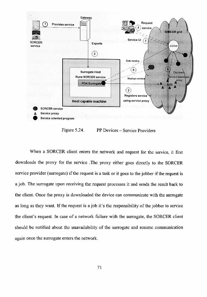
Gateway
nio Provides service
SORCER service
r
9 SORCER service
A Service proxy
9 Service oriented program
Surrogate Host
Runs SORCER service
PDA Surrogates-
Host capidile machine
© Registers service"^
using service proxy
Figure 5.24. PP Devices - Service Providers
When a SORCER client enters the network and request for the service, it first
downloads the proxy for the service .The proxy either goes directly to the SORCER
service provider (surrogate) if the request is a task or it goes to the jobber if the request is
a job. The surrogate upon receiving the request processes it and sends the resuU back to
the client. Once the proxy is downloaded the device can communicate with the surrogate
as long as they want. If the request is a job it's the responsibility of the jobber to service
the client's request. In case of a network failure with the surrogate, the SORCER client
should be notified about the unavailability of the surrogate and resume communication
again once the surrogate enters the network.
71

5.6 Advantages
- Distributed use of vast resources anywhere, anytime by PDA's
^ Resource constrained mobile devices can now act as both service provider and
consumer in the SORCER grid
^ Provides a generic framework for integrating mobile clients with the SORCER
grid
> Secure, portable, scalable, and standards based grid computing for PDA's.
5.7 Framework Design
The generic design of SPPGF has been designed to integrate PP devices to the
SORCER.grid network to both access services from grid and provide services to the grid.
This framework shown in Figure 5.4 basically extends the SOA fimctionality of
SORCER.grid and Jini Madison Surrogate Architecture to perform service oriented
computing with PP mobile devices. The two main components of this design are
> Generic gateways - To provide access to SORCER.grid for PP devices.
> Generic Service Provider - To provide SORCER service from PP devices.
5.7.1 Generic Gateways
The gateways are buiU using java servlets to act as a intermediary between the
SORCER.grid and the PP devices. The basic design of these gateways extends from the
Java servlet pattern using the javax.http.servlet.These gateways are designed to support
the discovery mechanism to discover services for PP devices and also to support Madison
adapter functionality to host the PP device service in the surrogate host.
72

SorcerProxy
ep.ir^F'roxif
getlmage ( )
[ Surrogsfe ' t 1
! adji/ate {) '
' deadruate ( j '
ServioeProvider
5
V • 'i'5i'i7*e.'fjce
getlmage ( )
Servi ce Accessor
;r;
I DBvio&Ser'Ac&Admin
Surrogate Provi der
zx
jafvaxservlet hrttp HTTPServlet
— Z T
PP Servlet
initO
doPostO
getPfoxy ( )
r t Surrogate Servlet
doPostO
terminate()
Hpplet [> CDC/ipplet
- ^ Ph'Mo liybum Pro VI der
m^-l
PhotoA] bu n-i Di sp jtcl-er -E rv lAt
doPoslO
^ - Ph.:.toiilbumDispat.:h.5r
Phc/toaJbijmPro:<
^ Phoio h Ibcirnlnfe.'far^
getAlbums ()
getPhotos(jlbumName)
Igetlmage ( albumNjme.photoName)'
Uses
\> J3V3 3 ^ Applet < ] Fhc^o/^pplet Servi oe Accessor
Figure 5.25. Framework for PP devices
In both cases the device has to know the location of the gateways. The gateways are
booted up to the network using Apache Tomcat web servers.
73

Surrogate Di spatcher
Use;
geiSutrO
ge)SurrDesc()
SurrogateHandler
registerfjafpile.desc)
terminaie( )
S'l^Apiplet
SurrogateRegistrar
register (id JjrFile.desc)
registerSurrogate(hostRec, surRec)
SurrogateServiet
doPostO
terminate ( )
A dapter
""A"-
Pticito ajbu m Di spatcher Ser\'let
doPostO
Part of
>
Pholo/y bu rn Dt spatcher
Uses
SurrogateSer^/er Thread
run n
AdapierConiexi •
TV -'
IPAdapterlmpI
PhotoAJ burn Provider
in i tO
getKeenAliveHandlei()
getproxy (innerProxy)
Figure 5.26. Generic gateway
> Service Discovery
The process of discovering a Jini service comes from the SORCER functionality
and the servlet just need to import the ServiceAccessor class and the interface and then
provide the appropriate interface for that service to be discovered to the
ServiceAccessor.The ServiceAccessor finds the right provider for the service using the
interface provided and retums the proxy for the service to the servlet. When a PP device
appears in the network and request for the service to the gateway, it uses the downloaded
proxy to get the service and sends the results back to the device. Here the request from
the device basically goes as a HTTP request using the HTTP protocol standards and the
74
service resuU is retumed back by the same mechanism. The proxy is the SORCER
provider proxy, which is smart proxy assigned for a particular service.
^ Service Adapter
As Madison provides the entire framework for mobile devices to host their
services, it all depends only on the adapter functionality to wire the service to Madison.
The adapter servlet designed for this SPPGF is SurrogateServiet, which follows the IP
Adapter pattern in Madison to send the service to Madison host. This servlet can now
provide the adapter functionality to pass the service to the Madison Surrogate host. This
has been accomplished by incorporating the IP Adapter classes that come with Madison
inside this servlet. This provides a generic design for all PP devices to just pass the
service from the PP device to this adapter servlet, which in tum provides it to the
Surrogate host. The service can be passed as jar file or can be an URL pointing to the
location of the jar file to the servlet .The servlet then checks the service and if its an jar
file it transfers it to the host else downloads it from the right location and then sends it.
5.7.2 Generic Service Provider
This service provider for the PP devices extends the basic provider functionality
from SORCER using the SorcerProvider and ServiceProvider classes. The service
provider designed for this SPPGF is PPSurrogateProvider, which mns the SORCER
service for the device inside Madison Surrogate host. This provider extends the
ServiceProvider class from SORCER and implements two interfaces Surrogate and
DeviceServiceAdmin from Madison. This class follows the stmcture from Madison
IPDeviceSurrogate which activates the SORCER provider using activate () method from
75

Madison. This provider exports the service for the PP devices as a SORCER service. Any
application that needs to provide a service just needs to subclass this provider and
provides its own functionalities. The gelkeepAliveHandler () method has to be used in the
subclass to verify it the PP device is still alive when providing the service. The
getProxyO can be implemented in the subclass to provide smart proxies .This provider
gets the required proxy for the service and loads the provider properties from SORCER
and exports it as a SORCER service inside Madison surrogate host. Any subclass of this
class can provide their respective type of implementation inside the init() method.
The following section shows an application for the PDA to consume Axis camera
service from SORCER.grid and export Photo album service to SORCER.grid using the
generic SPPGF designed. This application has been successfully tested using SHARP
ZAURUS SL-5600 PDA.
5.8 Implementation
The SPPG framework has been implemented on the SORCER environment with
certain standards to meet the requirements of Service oriented Architecture model. The
specifications of various technologies were integrated and layered upon each other to
build the technical architecture for the SPPG framework. This architecture has served to
package the framework and the application into functionality specific packages in the
SORCER environment for better representation and reuse. These packaged components
were then installed on various platforms to test the robustness and scalability of the
framework and design.
76

5.8.1 Technical Architecture
This architecture specifies the underiying blocks of the SPPG framework and also
the various technologies that constitute the model and design. Built on a concrete Java
platform, this architecture utilizes the functionality of various technologies including
J2ME, Jini, CDC, Surrogate architecture to provide a unified design as shown in the
Figure 5.6.
Java Platform
Figure 5.27. Technical Architecture
5.8.2 Package Diagrams
As said earlier, the various functionalities in the framework were categorized and
were packaged into different sections depending up on their usage and deployment.The
core classes of the SPPG framework were built on the top of SORCER classes and were
packaged into
77
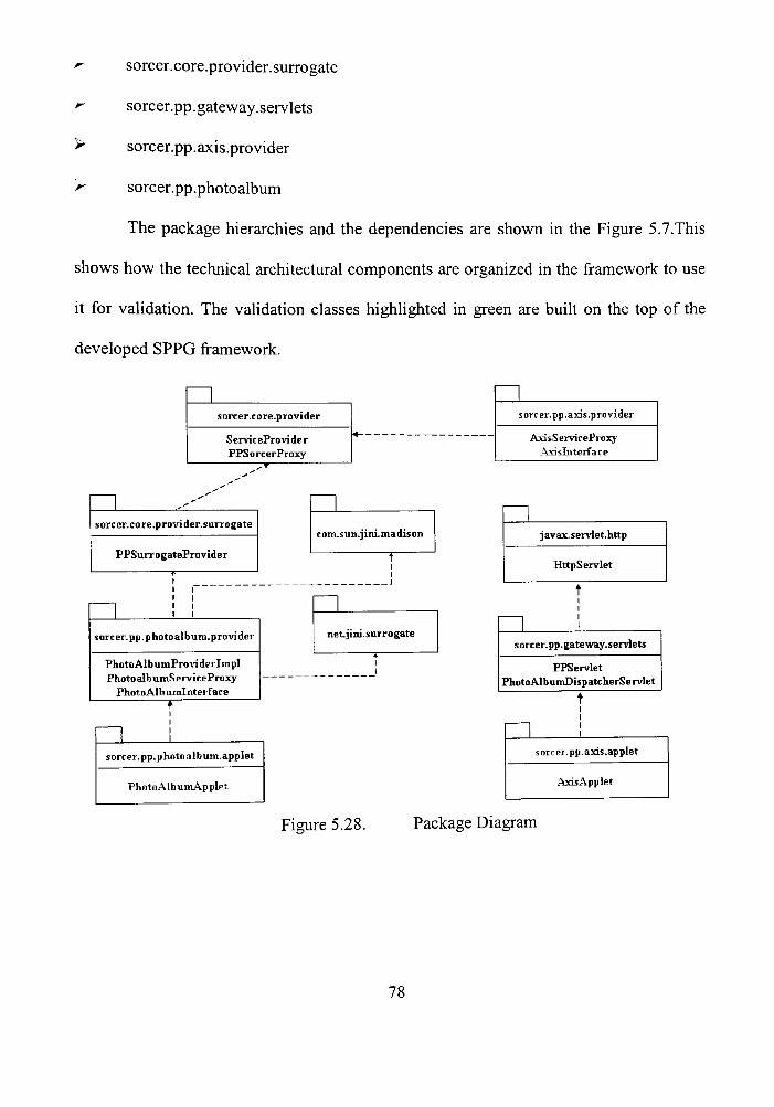
^ sorcer.core.provider.surrogate
- sorcer.pp. gateway, servlets
> sorcer.pp.axis.provider
f^ sorcer.pp.photoalbum
The package hierarchies and the dependencies are shown in the Figure 5.7.This
shows how the technical architectural components are organized in the framework to use
it for validation. The validation classes highlighted in green are built on the top of the
developed SPPG framework.
sorcer.core.provider
S ervic ePro vi de r PPSorcerProxy
sorcer.pp.axis.provider
AxisServiceProxy Axisliiterface
sorcer.core.provider.surrogate
PPSurrogateProvider
sorcer.pp.photo album.provider
PhotoAlbumProviderlmpl Photo albumServiceProxy
PhotoAlbumlnterface
com.sun.jini.madison
net. jini. surrogate
javax.servlet.http
HttpServlet
sorcer.pp.gateway.servlets
PPServlet PhotoAlb umDispatc herSe rvlet
sorcer.pp.photoalbum.applet
PhotoAlbumApplet
sorter, pp.axis.applet
Axis Applet
Figure 5.28. Package Diagram
78

5.8.3 Physical Architecture
This SPPGF has been successfully deployed on various platforms to test its
robustness and scalability. Operating systems includes windows, Linux, UNIX and
embedded Linux. The validation involved deploying the application on the respective
service nodes and the video and photo album application has been with the physical
architecture shown in Figure.
Axis Camera )
Sorcer Zaurus PDA n SPPG
Surrogate Host ^ beryl 4 fV Photo album Provider A . 3.2 Win XP
neem Linux
A 3.3 ^ Class Server )
mukundan Win XP Laptop
J in ! LUS Yew
Solaris
1.4
Figure 5.29. Physical Architecture
5.9 Validation
The following section describes a photo album application that would validate the generic
framework designed for PP devices. This application utilizes this SPPGF both to
consume /provide services to/from PDA.This application basically extends all the generic
79
classes of the framework to completely fianction on a PDA. Validating the framework is
carried out as a two fold process which are described as follows.
r- Image Requestor PDA continuously requesting images every second from a
SORCER provider providing camera service thus acting as a service consumer
from the network.
r- Photo Album Provider - PDA saving the images from the remote camera and the
sharing the saved images as a photo album service to the SORCER.grid network.
5.9.1 PDA as Image Requestor
The SORCER camera service is provided by the AXISCAMERA PROVDDER
and the PDA acts as image requestor requesting images every second from the camera.
The provider is directly implemented as a proxy class named as AxisServiceProxy
extending SorcerProxy class and implementing AxisInterface.This class provides a smart
proxy to the provider and exports this camera service on to the network.
80

Gateway]
:PPServtet
Request Image
FoRrtiards Image
Sends Image
^
Request Image j
I
JiniJ :Reqi5trar
T
Downloads Proxy
Oets Image
^ets Image
SORCER ServiceJ
/^j^isSer/iceProxv A X I S
Camera
I I I I
Figure 5.30. Image Requestor
The Image Requestor in the PDA has been designed as an applet named as
AxisAppIet which sends a request to the PPServlet which acts as a gateway for the
PDA.The PPServlet finds the camera service using the Axislnterface and downloads the
AxisServiceProxy which is a smart proxy. Once the proxy is downloaded it goes to the
camera and downloads the image and sends it to the PPservlet which in tum sends the
bytes to the AxisAppIet which displays the image.AxisApplet keeps requesting images to
the gateway every second and thus displays continuous stream of images from the
camera.
5.9.2 PDA As Photo Album Provider
The images being streamed continuously from the camera can be locally saved on
to the PDA by the AxisAppIet.These images can now be exported by the PDA to the
81
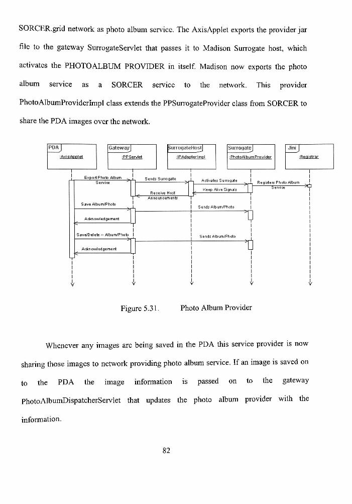
SORCER.grid network as photo album service. The AxisAppIet exports the provider jar
file to the gateway SurrogateServiet that passes h to Madison Surrogate host, which
activates the PHOTOALBUM PROVIDER in itself Madison now exports the photo
album service as a SORCER service to the network. This provider
PhotoAlbumProviderhnpl class extends the PPSurrogateProvider class from SORCER to
share the PDA images over the network.
Gateway]
:PP Servlet
surroyateHostJ
:IPAdapterlmpl
Surrogate]
iPhotoAJbumProvider
Jini
: Registrar
Sends Surrogate
Receive Host Announcements
Activates Surrogate
Keep AJive Signals
Registers Photo AJbum • ^ f i
ends Album/Photo
Sends Album/Photo
I
I I I I I I
I
Figure 5.31. Photo Album Provider
Whenever any images are being saved in the PDA this service provider is now
sharing those images to network providing photo album service. If an image is saved on
to the PDA the image information is passed on to the gateway
PhotoAlbumDispatcherServlet that updates the photo album provider with the
information.
82

5.9.3 Client using Surrogate Service
This PhotoAlbum provider has been tested using a SORCER client that looks for
this service and can now get the images stored on the PDA.This client has been
implemented as an applet PhotoAlbumApplet that uses the PhotoAlbum interface to
discover the service. This applet goes to the lookup services and finds the Photo album
provider and can now see the pictures stored on the PDA.
Stand Alone]
:PI-iQtQADDlet
Jini
: Registrar
Request Senrice
Downloads Prow/
Gets Albums
Gets Photos
Gets Image
I I
Surrogate]
:Phcrto/>l bum Provi cter
Request /v lb urns
Request Photos
Request Photo Image
v
I I
Figure 5.32. Client using PDA service
5.9.4 Testing and ResuUs
This entire application has been successfully tested in the ZAURUS environment
and the resuUs have proven to be extremely satisfied. The following key points have been
noted during testing.
83

> The PDA was able to get images every second from the camera and display it
continuously without any flickering. The size of the image has been nearly
compressed to half the original size to fit it in the PDA.
> Exporting the photo album service seemed to be very easy by just providing the
location of the photoalbum.jar file to the gateway.
> Images were saved properly on to the PDA without any difficulties and were
exported to the SORCER grid network at the same time it is saved.
> Once the image was deleted from the PDA, it was automatically deleted from the
network thus strengthening the quality of service provided by a mobile device.
SORCER has provided this SPPGF to be successful enough to mn mobile
applications and from now on any PP device can use SORCER to consume and provide
services to the network.
5.10 Conclusions
SOA appears to be architecture and a programming model, a way of thinking
about building software to support all kinds of devices. The conceptual model of
SORCER is generic SOA and can be implemented on any platform that supports
discovery and join protocols. My research has extended this SOA of SORCER to
integrate PP mobile devices into Service Oriented Computing. This SPPGF is a generic
framework that can support wide variety of devices without any platform barriers. This
framework integrates the PP devices to SORCER.grid network in such a way that these
devices not only consume services but can also provide their own services to the
84
SORCER.grid. Future extensions of this framework will lead us to witness mobile
services being offered anywhere and everywhere.
5.11 Future Research
Security has always been foremost important factor for any network transactions
and communications over the network. This generic framework though has been tested
successfully with a mobile device it still lacks the secure communication. Any service
can only be used only if it is tmsted that it is coming from an authenticated source.
Security has to be added on this PDA service so that anybody who uses the service can be
sure to tmst the service being provided. Moreover this framework is a one-way process
wherein a service provided from a mobile device is now only being utilized by PC's and
other systems capable of supporting Jini discovery mechanisms. This can be modified so
that any mobile device should be able use this service without any restrictions. This
framework needs to include service UI so that any client can use it without any
downloads to use a service. This framework can be extended in such a way that any data
updated from the cUents can be sent to the mobile devices .This process would be useful
for fixing appointments through a mobile device.
85
GLOSSARY/ABBREVATIONS
SORCER SOP SOA J2ME CDC PP MDDP SPPGF
HTTP TCP/IP
UDP RMI XML
Service-Oriented Computing Environment. Service-Oriented Programming Service-Oriented Architecture Java 2 Micro Edition Connected Device Configuration Personal Profile Mobile Information Device Profile Surrogate Personal Profile Gateway Framework Hyper Text Transfer Protocol Transmission Control Protocol/Internet Protocol User Datagram Protocol Remote Method Invocation Extended Markup Language
86

REFERENCES
1) http://developers.sun.coni/techtopics/mobility/configurations/articles/cdc/
2) http://jaya.sun.com/j2me/overview.htmI
3) Jini in Nutshell
4) http://pandonia.canberra.edu.au/java/jini/tutorial/Overview.xml
5) Jini architecture: dynamic services in a flexible network
6) http://vyvyws.sun.com/software/jini/whitepapers/architecture.html
7) http://wvyw.smarthomefomm.com/start/jini.asp
8) http://vyvyw.cswl.com/whiteppr/tutorials/jini.html
9) Retrieved from Intemet: Surrogate Architecture overview, pdf
10) Retrieved from Intemet:Surrogate Architecture.pdf
11) Retrieved from Intemet :Reaching out cell phone with Jini.pdf
12) Retrieved from Intemet :Jini Architecture: Dynamic services in flexible network
13) http://vyvyw.jini.org/nonay/standards/davis/doc/specs/html/devicearch-spec.html
14) http://wvyw.cisco.com/univercd/cc/td/doc/cisintwk/ito_doc/ip.htm
15) http://vyww.jini.org/standards/sa-ip.pdf
87
16) http://surrogate.jini.org/
17) http://ipsurrogate.jini.org/specs.html
18) Retrieved from Intemet :Wendylee.pdf
19) Retrieved from Uitemet :Madison design-doc.pdf
20) http://vyvyw.cablingsystems.coni/Issues/ISarticle.asp
21) http://vyvyw.bitpipe.com
22) Retrieved from Intemet:SuccessfulWireIessSolution_wp_web.pdf
23) www.javapassion.com/jini/surrogate4.pdf
24) http://serylet.java.sun.coni/javaone/javaone2000/pdfs/TS-763.pdf
25) http://vyww.broadcastpapers.com/data/InfovalueQV04.htm
26)http://dsg.port.ac.uk/~mab/Tutorials/EP2K3/JiniTheDavisProject(4).ppt
27) http://searchwebservices.techtarget.com
28) http://vyvyw.tdap.CO.uk/uk/archive/mobile/mob(sun_0009).html
29) http://searchmobilecomputing.techtarget.coni/
30) http://vyww.sorcer.cs.ttu.edu/sorcer-mobiIity.pdf
31) http://wvyw.xml.eom/pub/a/ws/2003/09/30/soa.html
88
32) http://www.service-architecture.com
33) http://www.ondotnet.coni/pub/aydotnet/2003/08/18/soa_explained.html
34) http://www.ceIlular.co.za/stats/stats-main.htm
35) http://www.tristardigital.com/html/wireless_wifi_products key_ar.html
89

PERMISSION TO COPY
In presenting this thesis in partial fiilfiUment of the requirements for a master's
degree at Texas Tech University or Texas Tech University Health Sciences Center, 1
agree that the Library and my major department shall make it freely available for research
purposes. Permission to copy this thesis for scholariy purposes may be granted by the
Director of the Library or my major professor. U is understood that any copying or
publication of this thesis for financial gain shall not be allowed without my further
written permission and that any user may be liable for copyright infringement.
Agree (Permission is granted.)
Studeitt-Signature Date
Disagree (Permission is not granted.)
Student Signature Date