a supplier’s perspective on the development of lead-free soldering ... - nihon superior.pdf · a...
TRANSCRIPT

A Supplier’s Perspective on the Development of Lead-free Soldering
Materials
Keith Howell Nihon Superior
Silicon Valley Chapter 13 November 2012

Agenda
Solder Paste Flux Development
Voiding Head-in-pillow
Lead-free Alloys Q & A

Customer Wants
Solder Assembly Materials Wide process window High first pass yield High reliability in service
Low Cost

Lead-free
Higher Processing Temperatures Slower Wetting Longer Profiles
Reflow Wave
More Demand on the Flux

Solder Paste

Solder Beading (Mid-Chip Balling)
Courtesy: FCT Assembly

Ref: Neil Poole & Brian Toleno, Henkel Corporation
Graping

Solder Paste Attributes
Prin%ng • Print Speed • Stability (Repeatability) • Stencil Release • Transfer Efficiency • Cold Slump • Small Feature Prin=ng • Stencil Life • Pause to Print • Cleaning Cycle
Reflow • WeAng • Reflow Window • Hot Slump • Bridging • Solder Balling • Graping • Voiding • Head-‐in-‐Pillow • Residues

Solder Paste Print Performance
Print performance is determined by the rheological Metal percentage Sphere size Topography of the powder Resin system Solvents Property modified additives

Alloy Surface Topography
SN100C SAC305

Resins
Organic acids More advanced organic materials
Ref: Cobar Solder Products

Flux System
Ref: Cobar Solder Products

Power semiconductor BGA
IPC-A610 Acceptability Standards of Electronic Assemblies
- ≤25%
JIS-C61191-6 Evaluation Criteria and Methods of Measurement of Solder Joint Voids in BGA and LGA
- <5%
Voiding

Voiding Issue?
Association Between Void and Crack Path?
IPC-A-610 says voiding up to 25% of X-ray image of the joint area is acceptable in Surface Mount Area Array joints

Composition of Medium
0% 50% 100%
Activators
Thixotropic Agents
Additives
Resins Solvents
Volatilization Decomposition Reaction Products
Gas!
Gas Evolution from Flux Medium

Void Reduction Strategy
Reduce Volatiles Release in Reflow Stage of Profile
Facilitate Escape of Volatiles
Improvement in Solder Paste Formulation
Use Solvent that Volatilizes During Preheat
Reduce Surface Tension of Solder

Bubbling in glass-covered solder paste during reflow

Air reflow Nitrogen reflow Vacuum reflow
General purpose paste
Voiding 6.01% 5.72% 2.02%
Low voiding formulation
Voiding 4.20% 2.83% 0.99%
Voiding Results

Head-in-Pillow

Head-in-Pillow
Courtesy of Renesas

HIP Mitigation
© Indium Corporation 2012

Head-in-Pillow Solutions
Component Warpage Temperature Profile Solder Paste
Oxidation Flux Activity Improved Wetting
Lower Process Temperature
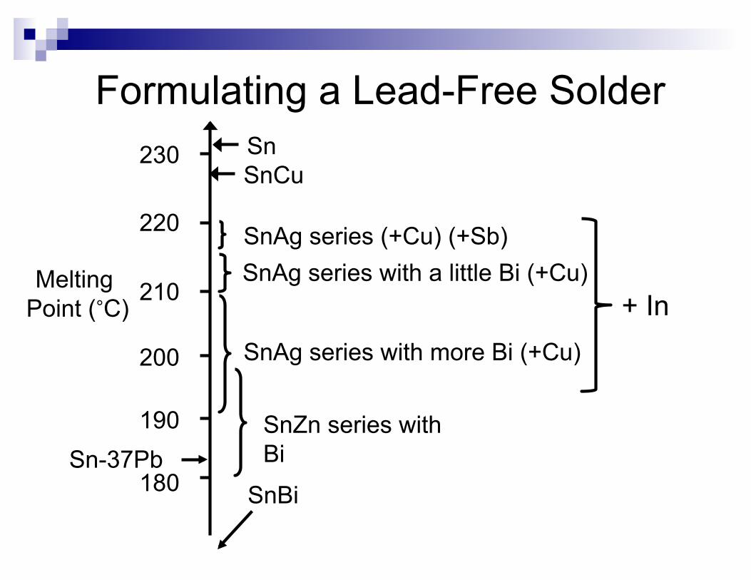
Formulating a Lead-Free Solder 230
220
210
200
190
180
Melting Point (°C)
SnAg series with more Bi (+Cu)
SnCu
SnAg series (+Cu) (+Sb) SnAg series with a little Bi (+Cu)
SnZn series with Bi Sn-37Pb
Sn
SnBi
+ In

Where Did It All Start?
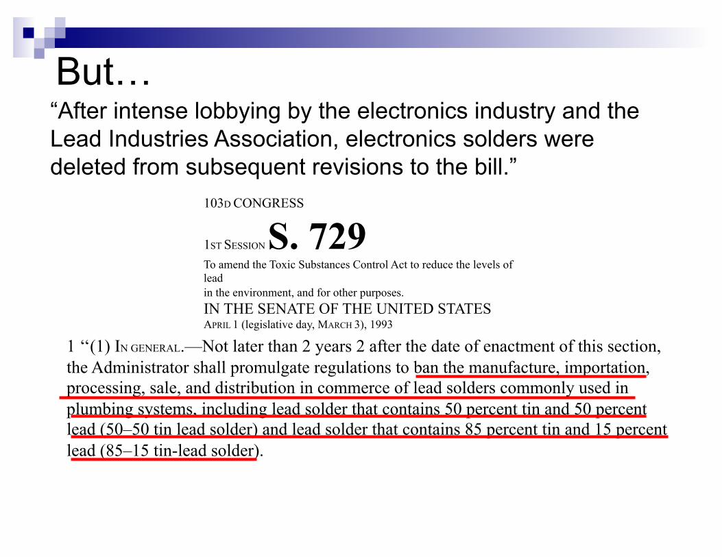
103D CONGRESS
1ST SESSION S. 729 To amend the Toxic Substances Control Act to reduce the levels of lead in the environment, and for other purposes. IN THE SENATE OF THE UNITED STATES APRIL 1 (legislative day, MARCH 3), 1993
1 ‘‘(1) IN GENERAL.—Not later than 2 years 2 after the date of enactment of this section, the Administrator shall promulgate regulations to ban the manufacture, importation, processing, sale, and distribution in commerce of lead solders commonly used in plumbing systems, including lead solder that contains 50 percent tin and 50 percent lead (50–50 tin lead solder) and lead solder that contains 85 percent tin and 15 percent lead (85–15 tin-lead solder).
But… “After intense lobbying by the electronics industry and the Lead Industries Association, electronics solders were deleted from subsequent revisions to the bill.”

In the meantime …
Q4 1998 the European Union issued a second draft of a directive on eliminating lead from electronics
Initially applies to Televisions, Air Conditioners, Refrigerators, Washing Machines Scheduled for Implemented April 1, 2001
1998 Japanese Diet enacted Home Appliance Recycling Law
The Japanese electronics industry realised that the economics of recycling would force them to eliminate lead

The Japanese electronics industry declared its intention of switching to Pb-free technologies
October 1998 Minidisk Player
Reflow with Sn-Ag-Bi-In
March 2009 VCR
Wave solder with SN100C
And then…

1. Member States shall ensure that, from 1 July 2006, new electrical and electronic equipment put on the market does not contain lead, mercury, cadmium, hexavalent chromium, polybrominated biphenyls (PBB) or polybrominated diphenyl ethers (PBDE).
DIRECTIVE 2002/95/EC of THE EUROPEAN PARLIAMENT AND OF THE
COUNCIL of 27 January 2003

Why SAC305?
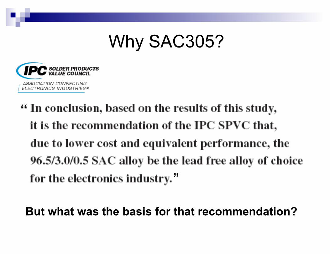
“
”
But what was the basis for that recommendation?
Why SAC305?

Why SAC305?
The three SAC alloys were compared on the basis of:
• Melting Point
• Wetting Rate
• Spread
• Reflow soldering
• Joint microstructure
• Thermal cycling of reflowed test assembly (0-100°C, 10 minute dwells)
• Thermal shock of reflowed test assembly (-40-125°C, 5 minute dwells)
• Cross-sectioning after thermal cycling

• Wave soldering
• Selective solder
• Hand soldering
• Rework
The three SAC alloys were NOT evaluated in:
Why SAC305?

The three SAC alloys were NOT evaluated for:
• Aggressiveness towards copper (Copper Erosion)
• Aggressiveness towards stainless steel (Solder Pot Erosion)
• Reliability in high strain situations (e.g. Vibration)
• Reliability in shock loading (e.g. Drop test)
Why SAC305?

Cu Erosion Example of Cu dissolution
Typically occurs at the knee
Ref: Celestica/IBM Study

Cu Erosion
Ref: Jeff Kennedy, Dave Hillman, Ross Wilcoxon – TEERM NASA DoD Phase 2
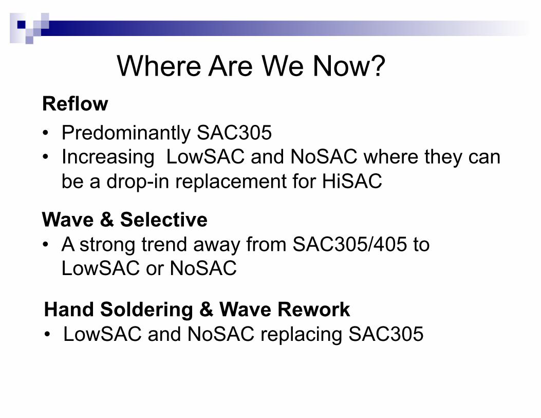
Reflow • Predominantly SAC305 • Increasing LowSAC and NoSAC where they can
be a drop-in replacement for HiSAC
Wave & Selective • A strong trend away from SAC305/405 to
LowSAC or NoSAC
Hand Soldering & Wave Rework • LowSAC and NoSAC replacing SAC305
Where Are We Now?

Legislation
RoHS REACH Canada – Rosin Ban California Prop 65 Chemicals of Concern Conflict Minerals EPA

Summary Most defects and reliability issues are
caused by the assembly materials Not true Materials are one component in the assembly
process Solder suppliers must work with component
and process equipment suppliers to meet customers’ demands

Summary (continued)
Solder material suppliers must continue to innovate and development materials to address new issues
“Horses for Courses” Application specific materials Chemists’ and metallurgists’ playground
