a summary of rotorcraft handling qualities robert t. n
TRANSCRIPT
A SUMMARY OF ROTORCRAFT HANDLING QUALITIES
RESEARCH AT NASA AMZS RESEARCH CENTER
Robert T. N. Chen NASA Ames Research Center Moffett Field, California
First Annual NASA Aircraft Controls Workshop NASA Langley Research Center
Hampton, Virginia October 25-27, 1983
51

OBJECTIVES AND SCOPE
The objectives of the rotorcraft handling qualities research program at Ames Research Center, as shown in figure 1, are twofold: (1) to develop basic handling qualities design.criteria to permit cost-effective design decisions to be made for helicopters, and (2) to obtain basic handling qualities data for certification of new rotorcraft configurations. The research on the helicopter handling qualities criteria has focused primarily on military nap-of-the-Earth (NOE) terrain flying missions, which are flown in day visual meteorological conditions (VMC) and instrument meteoro- logical conditions (IMC), or at night. The Army has recently placed a great deal of emphasis on terrain flying tactics in order to survive and effectively complete the missions in modem and future combat environments. Unfortunately, the existing Military Specification MIL-H 8501A (ref. l), which is a 1961 update of a 1951 document, does not address the handling qualities requirements for terrain flying. The research effort is therefore aimed at filling the void and is being conducted jointly with the Army Aeromechanics Laboratory at Ames. The research on rotorcraft airworthiness standards with respect to flying qualities requirements has been conducted in collaboration with the Federal Aviation Administration (FAA). This effort focused, in the recent past, on helicopter instrument flight rules (IFR) airworthiness criteria and is now addressing the airworthiness concerns for such new rotorcraft configurations as tilt-rotor aircraft.
OBJECTIVES
DEVELOP FLYING QUALITIES AND CERTIFICATION CRITERIA
SCOPE
. NOE OR TERRAIN FLIGHT IN VMC AND IMC/NlGHT (ARMY)
. TERMINAL AREA IFR OPERATIONS (FAA)
. NOE @ CONTOUR @ LOW LEVEL @
Figure 1
52

FACTORS INFLUENCING AGILITY FOR TERRAIN FLIGHT
In terrain flight, the pilot is often called upon to fly complicated and rapidly changing trajectories to avoid obstacles and to unmask and quickly remask. The characteristics of the helicopter that permit the pilot to fly these complex trajectories quickly, precisely, and easily are essential to safe and successful operations, and we may define this aggregate of characteristics as agility. Factors influencing agility are many: basic performance potential of the aircraft, engine/ governor dynamics, stability and control characteristics, and cockpit interface (fig. 2). For quickness, the helicopter must be able to change rapidly the magnitude and direction of its velocity vector. Adequate control powers in pitch, roll, and yaw are required for a quick rotation of the thrust vector; adequate installed power and responsiveness of the engine/governor system together with adequate rotor thrust capability are needed to meet the demand for rapid changes in thrust magnitude. For precision and ease with which the pilot flies those complex trajectories, the heli- copter must have good stability and control characteristics. Interaxis coupling must be minimized so that unnatural or complicated control coordination is not required. Also, proper controller characteristics, flight director displays, and vision aids are needed to assist the pilot in flying the missions in adverse weather conditions or at night.
AGILITY: THE QUALITIES PERMITTING PILOTS TO FLY COMPLEX TRAJECTORIES QUICKLY, PRECISELY, AND EASILY
QUICKNESS 0 ABILITY TO RAPIDLY CHANGE MAGNITUDE AND DIRECTION OF AIRCRAFT VELOCITY VECTOR
. INSTALLED POWER, RESPONSIVENESS OF ENGINE/GOVERNOR SYSTEM
. ADEQUATE CONTROL POWER IN PITCH, ROLL, YAW
. ADEQUATE ROTOR THRUST CAPABILITY
EASE AND 0 GOOD COMBINATIONS OF STABILITY AND CONTROL, AND PRECISION ADEQUATE PILOT AIDS
l ADEQUATE DAMPING, PROPER CONTROL SENSITIVITY
. SMALL INTERAXIS COUPLING
. ADEQUATE STABILITY
. PROPER COCKPIT INTERFACE AND PILOT AIDS
- CONTROLLER CHARACTERISTICS
- DISPLAYS (IMC)
- VISION AIDS (NIGHT)
Figure 2
53

EFFECT OF ENGINE DYNAMICS ON HANDLING QUALITIES
The effects of engine dynamics and thrust-response characteristics on helicopter handling qualities have until recently remained largely undefined. A multiphase pro- gram is being conducted to study, in a generic sense, the effects of engine response, rotor inertia, rpm control, excess power, and vertical sensitivity and damping on helicopter handling qualities in hover and representative low-speed NOE operations. To date, three moving-based piloted simulations have been conducted on the Vertical Motion Simulator (VMS) at Ames. This series of investigations concentrates specifi- cally on the helicopter configuration with an rpm-governed gas-turbine engine. It was found (ref. 2) that variations in the engine governor response time can have a significant effect on helicopter handling qualities as shown in figure 3. For the tasks evaluated, satisfactory handling qualities and rpm control were achieved only with a highly responsive governor (which for the model in the study was wn > 7 radlsec). The results indicate that for satisfactory handling qualities, there is a qualified trade-off between engine response time and vehicle vertical damping; however, increases in engine time constant are limited by poor rpm overspeed and underspeed control.
40 knot QUICK STOP DOLPHIN BOB UP AND DOWN
1.a I-
I-
i-
6.5 5;3 AVERAGE COOPER- 1 1 .oo .
/ HARPER RATING
III / 6.5 5.5
. .
5 ,,I’ I’ l
. #- .50
4.5 $1’ 3.7 g
’ ,I’
II 3.2 Ii. .,w.25
I’ SATIS- FACTORY
0
4.0 .
IDEAL ENGINE 2, = -0.65 set-l 1 P.R. = 3.0
EQUIVALENT TENG < 0.2 FOR SATISFACTORY
- OPTIMIZED
SATISFACTORY 3.0
0 Z 4 6 w,,, radlsec
8 10 0 -2 -4 -6
Z,, set-’
Figure 3
54

EFFECT OF EXCESS THRUST, ROTOR INERTIA, AND RPM CONTROL ON HELICOPTER HANDLING QUALITIES
The excess power requirements (T/W) for the NOE tasks were investigated with various levels of vehicle vertical damping Z,. Results indicated that the required level of T/W is a strong function of Zw as shown in figure 4, and is minimized ata Z, value around -0.8 rad/sec. In addition to the required engine response time (as previously shown in fig. 3), an excess power level of T/W=l.l is required to achieve satisfactory handling qualities for the bob-up task.evaluated. The thrust response of a helicopter, unlike that of fixed-wing VTOL aircraft, is influenced by several factors, including (1) engine governor dynamics, (2) vertical damping result- ing from rotor inflow, and (3) the energy stored in the rotor, which is a function of rotor inertia. The experimental results (ref. 3) indicate, however, that increases in rotor inertia (thus the stored kinetic energy) have only a minor and desirable effect on handling qualities. The effect on handling qualities of requirements for pilot monitoring and control of rotor rpm can be significant. For a slow engine governor, the degradation in pilot rating in the bob-up tasks was as much as two ratings. It may therefore warrant consideration of techniques to relieve the pilot of the task and concern for monitoring proper rpm.
(BOB-UP TASK)
Z, vs T/W
ADJUSTED L2 83300
lo- EFFECTS OF INERTIA EFFECTS OF RPM CONTROL
is g- (Z,= -0.25sec-'1 Jp = 2000 slug ft2
$ 8- Z,= -0.25sec-'
SLOW-RESPONSE $ IO-
F DEGRADATION DUE
0 rpm CUEING
DEGRADATION DUE TO
1 ’ INCREASING 7RT(l/wn) - GOVERNOR DYNAMICS
I I I 6
8 O I I I 1
200 1000 2000 3000 4000 IDEAL FAST INTER- SLOW Jp, slug ft2 MEDIATE
ENGINE - GOVERNOR RESPONSE
Figure 4
55
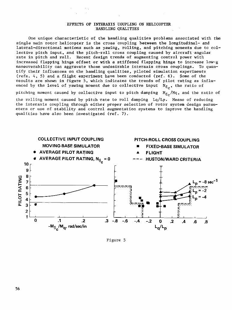
EFFECTS OF INTERAXIS COUPLING ON HELICOPTER HANDLING QUALITIES
One unique characteristic of the handling qualities problems associated with the single main rotor helicopter is the cross'coupling between the longitudinal- and lateral-directional motions such as yawing, rolling, and pitching moments due to col- lective pitch input, and the pitch-roll cross coupling caused by aircraft.angular rate in pitch and roll. Recent design trends of augmenting control power with increased flapping hinge offset or with a stiffened flapping hinge to increase low-g maneuverability can aggravate those undesirable interaxis cross couplings. To quan- tify their influences on the handling qualities , piloted simulation experiments (refs. 4, 5) and a flight experiment have been conducted (ref. 6). Some of the results are shown in figure 5, which indicates the trends of pilot rating as influ- enced by the level of yawing moment due to collective input Ng,, the ratio of
pitching moment caused by collective input to pitch damping MBc/Mq, and the ratio of
the rolling moment caused by pitch rate to roll damping Q/Q. Means of reducing the interaxis coupling through either proper selection of rotor system design param- eters or use of stability and control augmentation systems to improve the handling qualities have also been investigated (ref. 7).
COLLECTIVE INPUT COUPLING
MOVING-BASE SIMULATOR
. AVERAGE PILOT RATING
ti AVERAGE PILOT RATING, Ng = 0 10 c
9 c
*t
PITCH-ROLL CROSS COUPLING
m FIXED-BASE SIMULATOR A FLIGHT
--- HUSTON/WARD CRITERIA
E
0 .l .2 -M6,/Mq, radhclin
.3 -.8 -.6 -.4 -2 0 .2 .4 .6 .8
LdLP
Figure 5
56

I
INTERACTION OF CONTROLLER CHARACTERISTICS, CONTROL LAW, AND DISPLAY
In support of the Army's Advanced Digital/Optical Control System (ADOCS) program, a series of piloted simulations (refs. 8-11) were conducted both at the Boeing Vertol facility and in-house on the VMS at Ames to assess the interactive influences of side- stick controller characteristics, level of stability and control augmentation, and a helmet-mounted display which provided a limited field-of-view image with superimposed flight control symbology. A wide range of stability and control augmentation system (SCAS) designs, ranging from the basic lJJ36OA heiicopter SCAS to a SCAS with transla- tional rate command/translational rate stabilization, was investigated. Variations in controller force-deflection characteristics and the number of axes controlled through an integrated side-stick controller as shown in figure 6 were studied. The handling qualities data base developed from this series of experiments for both day visual and night/adverse weather terrain flying tasks will be used not only for the design of the ADOCS demonstrator helicopter but also as design data for future mili- tary rotorcraft such as JVX and LHX.
SCAS DESIGN - COMMAND/STABILIZATION CHARACTERISTICS
THREE-DIMENSIONAL FLIGHT
SSC CONFIGURATION
HMD SYMB AT + FLIR
f
‘?- “MC &
HMD 0
: ATTITUDE CMD/ATTITUDE STAB
CONTROLLER CONFIGURATIONS COLLECTIVE
COLLECTIVE +
PITCH /‘i- ROLL
4-AXIS I (3+1) PEDALS
COLLECTIVE
COLLECTIVE
- 2+1+1 1 /3+1) COLLECTIVE
Figure 6
57
-

COMPARISON OF IMC AND VMC PILOT RATINGS
The results of this series of simulation experiments show that an integrated four-axis force controller with small deflection in all axes was preferred to other four-axes devices with no deflection (stiff stick). With small deflection, the pilot's ability to modulate single-axis forces was improved and the tendency to over- control or to produce input coupling was reduced. The results also indicate (ref. 9) that level of stability and control augmentation has a dominant effect on NOE handling qualities. With a high level of augmentation, satisfactory handling quali- ties for NOE tasks were achieved for all the three levels (two to four axes) of integrated force controllers having small deflection as shown in figure 7. However, the fully integrated (four-axis) controller degraded handling qualities compared to separate controllers for such large-amplitude multiaxis control tasks as a decelerat- ing turning approach to hover and a high-speed slalom maneuver. Mission tasks flown under the simulated reduced visibility conditions received pilot ratings two or more rating points worse than the identical tasks flown under day VMS conditions.
NOE TASK
. VMC
A IMC
s 10
1 (4 + 0)
F 9 (3+l)c 2+1+1
LEVEL 3 (UNACCEPTABLE)
&-,A
\
LEVEL 2 (ACCEPTABLE)
\\\\\\\\\\\ \\\ ’ c s 2t
VMC LEVEL 1 (SATISFACTORY)
: ,I I I J I I I
RA/AT AT/AT AT/LV RAIAT AT/AT AT/LV RA/AT AT/AT AT/l PITCH/ROLL AFCS CONFIGURATION
.V
Figure 7
58

INFLUENCE OF LOAD FACTOR AND TURN DIRECTION ON MODE SHAPE
With ever-increasing military demands for agility and maneuverability of rotor- craft, there is a need to better understand the flight dynamics of rotorcraft in such large-amplitude, asymmetric maneuvers as steep, high-g turns. To meet this need, an analytical procedure has been developed to permit a systematic investigation of rotor- craft dynamic characteristics in steep, high-g turns (refs. 12-14). Numerical exami- nations of a tiit-rotor aircraft and several single-rotor helicopters with different types of main-rotor systems have been conducted. .It has been found that strong coupling exists , particularly at low speeds, between the longitudinal- and the lateral-directional motions in high-g turns for both the symmetrical and asymmetrical- type rotorcraft; flying qualities and flight-control design analyses based on small disturbances from straight flight are grossly inadequate for predicting flight dynamics in high-g maneuvers. For example, for single-rotor helicopters the direc- tion of turn has a significant influence on the flight dynamic characteristics in high-g turns. Figure 8 illustrates the effects of load factor and turn direction on the eigenvector of the Dutch-roll mode for a study hingeless rotor helicopter in level turns at 60 knots.
2-g LEFT TURN
AU Aci Ag Ae Ap Ap Acj I , L
l-g STRAIGHT LEVEL
n
AU Aa Ag A0 A/3 Ap A@ Ar
AP
AP
2-g RIGHT TURN Aq A@ Ae AU
AP 4 ACY
“; AU Aa Aq Ae Ap Ap A@ Ar
Ar t Ar
Figure 8
Ir
59

EFFECT OF LOAD FACTOR, TURN DIRECTION, AND UNCOORDINATlUN ON CONTROL RESPONSE
The developed analytical procedure also permits a systematic examination of statics and flight dynamics of rotorcraft in various levels of uncoordinated high-g turning maneuvers. Examinations of several rotorcraft indicate (1) that the aircraft trim attitudes in uncoordinated high-g turns can be grossly altered from those for coordinated turns, and (2) that within the moderate range of uncoordinated flight (side force up to +O.l g), the dynamic stability of these rotorcraft is relatively insensitive. However, the coupling between the longitudinal- and the lateral- directional motions is strong, and it becomes somewhat stronger as the sideslip increases. Examinations of the effect of uncoordinated high-g turns on the perfor- mance of a stability and control augmentation system designed using linear quadratic synthesis techniques indicate that the aircraft response with the SCAS on can degrade as sideslip increases. The influence of sideslip, however, is found to be less drastic than that of either load factor or turn direction as illustrated in figure 9 (ref. 14). In addition, the study also assessed the individual effects of the aerodynamic, kinematic, and inertial coupling on the flight dynamics of rotorcraft in steep turns.
- 1 g FLIGHT (WITHOUT SCAN 2 g RIGHT TURN, - - - 1 g FLIGHT (WITH SCAS) b ny = 0 (WITH SCAS) + 2 g LEFT TURN, ny = 0 (WITH SCAS) -- - ny = 0.10 (WITH SCAS)
-..- n Y = -0.05 (WITH SCAS)
sJ;y, , EL - 0 2 4 6 8 10 12 0 2 4 6 8 10 12
TIME, set TIME, set
Figure 9
60

HELICOPTER IFR AIRWORTHINESS CRITERIA
We now turn to the rotorcraft certification criteria research. The rapid expansion of civil helicopter operations has led to increasing efforts to assess problem areas in civil helicopter design, certification, and operation. A joint NASA-FAA program was instituted at Ames to investigate the influence of the helicop- ter's inherent flight dynamics, flight control system, and display complement on flying qualities for IFR flight, both in terms of design parameters to ensure a good IFR capability and with regard to the characteristics that should be required for certification. The specific areas of concern that were addressed include (1) the requirements for stable force or position control gradients; (2) the difference in criteria for normal-category rotorcraft, depending on whether the aircraft is to be certified single or dual pilot; and (3) the SCAS and display requirements for decelerating instrument approach to exploit the helicopter's unique capability to fly at very low speeds. Five ground-based piloted simulations and one flight experiment were conducted during a 3-yr period beginning in 1978 (refs. 15 and 16). These experi- ments were summarized in figure 10 in terms of the specific objectives, the task evaluated, and the facility used.
EXPERIMENT SUMMARY -
EXPERIMENT TASK OBJECTIVES FACILITY DATE
1 . CONST. SPEED VOR l HELICOPTER MODELS . DUAL PILOT l SCAS IMPLEMENTATION FSAA NOV 78
2 . CONST. SPEED VOR . STATIC STABILITIES . DUAL PILOT l SCAS IMPLEMENTATION FSAA MAR 79
. CONST. SPEED MLS l FLIGHT DIRECTORS AND 3 . SINGLE AND DUAL CONTROL-DISPLAY FSAA MAR 80
PILOT l CREW LOADING
. CONST. SPEED MLS . VALIDATE GRD. SIM. 4 . DUAL PILOT RESULTS FOR STATICS, FLIGHT: SEP 80
SCAS, AND FLIGHT UH-IH DIRECTORS
l CONST. SPEED MLS . LONGITUDINAL DOF 5 . DUAL PILOT . STATIC AND DYNAMIC VMS NOV 80
CRITERIA
6 . DECELERATING MLS l INSTRUMENT DECELERATION . DUAL PILOT . ELECTRONIC DISPLAYS VMS OCT 81
Figure 10
61

INFLUENCE OF LONGITUDINAL CONTROL GRADIENT
Regulations (ref. 17) require positive longitudinal control force stability at approach speeds for both transport and normal-category helicopters, regardless of crew loading. This requirement is probably justifiable for rate-damping types of SCAS, although little significant degradation has been shown with neutral or slightly unstable gradients; hence, the neutral gradient, at least, could be considered marginally acceptable. Figure 11 shows the results of this series of experiments, which indicate the trend of handling qualities as influenced by static longitudinal stability for the rate-damping type of SCAS. Note that with this type of SCAS, average ratings in the satisfactory category were not achieved, even at the most stable level. In commenting about these configurations, the pilots noted increasing difficulties in maintaining trim and controlling speed precisely as the static stability was decreased, but they also noted that the instrument tracking performance was still adequate at least to neutral stability. It should be empha- sized that a rate-command attitude-hold type of SCAS results in a neutral longitudinal gradient; this type of SCAS was generally rated in the satisfactory category. Hence the requirement of control gradient may have to be linked to the type of SCAS employed, which it currently is not.
EXPERIMENT 0 1 FSAA A 4 UH-1H @ 2 FSAA v 5 VMS l 3 FSAA + 6 VMS
8 r INADEQUATE T _
SATISFACTORY 2-
STABLE - ) UNSTABLE I I I I I I I
-1.0 -.8 -.6 -.4 -.2 o .I -2
6 Es/v, in/l 5 knot 1flD. lhec
Figure 11
62

Most helicopters currently certified for single-pilot IFR operations employ advanced SCAS or displays or both. Of concern is the level of complexity of the SCAS required to achieve a good IFR capability because of the cost, control authority, and reliability factors the SCAS introduces. The influence of SCAS on the IFR handling qualities was therefore investigated. As shown in figure 12, three types of pitch and roll SCAS, among others, were considered: rate damping with input decoupling, rate command-at,titude-hold (RCAH), and attitude command (AC). These cases are primarily for the SCAS incorporated on a machine with neutral basic longi- tudinal stability. Note that a rate-damping SCAS does not alter the control position gradient, a RCAH SCAS results in a neutral gradient (as described earlier), and the attitude SCAS stabilizes the gradient because of the MO term. As. indicated in figure 12, rate-damping augmentation, even at a fairly high level and with input decoupling, generally has received pilot ratings from marginally adequate to just worse than satisfactory. Attitude augmentation in pitch and roll (implemented either as RCAR or AC) is required to achieve satisfactory handling qualities for IFR opera- tions in turbulence. With attitude augmentation, the interaxis coupling and turbu- lence excitation are reduced and short-term and long-term dynamics are improved.
EXPERIMENT 0 1 FSAA A 4 UH-1H u 2 FSAA 'I 5 VMS l 3 FSAA + 6 VMS
8
6
E4 ::
2
INADEQUATE / STABLE BASELINE
GRADIENT
I n
ADEQUATE
SATISFACTORY
NO RATE SCAS RATE RATE ! ATTITUDE (LONGITUDINAL) DfpPI;G COMMAND COMMAND
ATTITUDE DECOUPLING
(NEUTRAL HOLD
GRADIENT)
Figure 12
63

INFLUENCE OF TASK DIFFICLJLTY
Since the pilot rating applies to a control/display combination for a specific task, and since the evaluation tasks varied somewhat across this series of experi- ments, it is instructive to show the influence of task on the ratings. Ratings from these experiments are compared in figure 13 for similar SCAS characteristics (rate SCAS and attitude-command SCAS) and displays (with and without three-cue flight director displays) as a function of the task evaluated. It is noted that the addition of three-cue flight directions generally improves ratings. Also, an increase in the task difficulty (e.g., single pilot or inclusion of an instrument deceleration) results in degraded ratings for equivalent configurations, Specifi- cally, the difference between the dual-pilot and single-pilot tasks is seen to be almost one pilot rating point. A difference in requirements' for single- and dual- pilot operations is warranted. In addition, it may also be seen from figure 13 that a decelerating instrument approach leads to worse ratings than even the single- pilot task with a constant-speed approach. More stringent criteria may therefore be required for decelerating instrument operations.
EXPERIMENT SYMBOLS 8
6
E4 5
2
INADEQUATE n 2 FSAA l 3 FSAA + 6 VMS
OPEN - RATE SCAS CLOSED - ATTITUDE SCAS
0 I3
0 ADEQUATE 0
0 0
0 0
l 0
0
SATISFACTORY
VOR MLS MLS MLS MLS MLS CONST. CONST. CONST. CONST. CO NST. DECEL. SPEED SPEED SPEED SPEED SPEED APPROACH DUAL DUAL SINGLE DUAL SINGLE DUAL PI LOT PI LOT PI LOT PILOT PILOT PILOT
\ / \ , * Y RAW DATA DISPLAYS FLIGHT DIRECTOR DISPLAYS
Figure 13
64

PILOT EVALUATIONS OF TILT-ROTOR TRANSITION
The first ground-based simulation experiment in a projected series of investi- gations was conducted by NASA and the FAA on the VMS at Ames to perform a preliminary assessment of airworthiness considerations for tilt-rotor aircraft in terminal area operations (fig. 14). Principal variables of the experiment were (1) visual versus instrument approaches, (2) the type of stability and control augmentation, and (3) three conversion profiles ranging from full conversion before the glide slope to full conver- sion on the glide slope. The results obtained in a recent study indicated that, for visual approaches, satisfactory performance within moderate pilot compen- sation was generally achievable irrespective of the conversion profile used; cross- winds and a moderate level of turbulence had a noticeably degrading effect with the baseline XV-15 SCAS but minimal influence with an attitude SCAS. For instrument approaches, the desired performance could be achieved with the attitude SCAS and the conversion profile having all conversion prior to the glide slope. It was also found that the marginally inadequate performance for the profile having all the con- version on the glide slope could be improved to the satisfactory level by adding automatic thrust tilt and three-cue flight directors.
VERTICAL MOTION SIMULATOR
10 CROSSWIND MODERATE TURBULENCE
9 0 BASIC SCAS
8 0 ATTITUDE SCAS INADEQUATE
OPEN - VFR
z7 - t CLOSED - IFR .._.
ADEQUATE
0
fl
3 SATISFACTORY
I! ’ I I I CONVERT CONVERT CONVERT ON BEFORE BEFORE GLIDE-SLOPE GLIDE-SLOPE AND ON
GLIDE-SLOPE
Figure 14
65

II I I llllll11llll III Ill I II II Ill1 II Ill lllllll I I
SUMMARY
In summary, we have briefly reviewed some major rotorcraft handling qualities research projects at Ames Research Center (fig. 15). They were grouped into two categories: (1) military rotorcraft handling qualities research, and (2) civil rotorcraft certification criteria research. In the first category, the research efforts that focus on determining the effects of engine and thrust response charac- teristics, interaxis coupling, controller characteristics control law/display inter- action, and large-amplitude maneuvers were highlighted. In the second category, efforts to develop IFR airworthiness handling qualities criteria for helicopters and tilt-rotor aircraft were discussed. Before concluding this discussion, it may be worth noting that a joint Army/Navy program is currently under way to update MIL-H-8501A. The objective is to develop mission-oriented handling qualities requirements for military rotorcraft (ref. 18). NASA's role related to the program is (1) to continue working with the Army (Aeromechanics Laboratory) to establish a comprehensive handling qualities data base and design guidelines for land-based military rotorcraft, and(2) to expand the scope to include research on developing rotorcraft handling qualities criteria for Navy shipboard mission tasks.
l MILITARY ROTORCRAFT HANDLING QUALITIES RESEARCH
- EFFECTS OF ENGINE AND THRUST RESPONSE CHARACTERISTICS
- EFFECTS OF INTER.AXIS COUPLING
- INTERACTIVE EFFECTS OF CONTROLLER/CONTROL LAW/DISPLAY
- EFFECTS OF LARGE AMPLITUDE (HIGH-g) MANEUVERS
l ROTORCRAFT CERTIFICATION CRITERIA RESEARCH
- HELICOPTER IFR TERMINAL AREA OPERATIONS
- TILT-ROTOR AIRCRAFT
Figure 15
66

REFERENCES
1. General Requirement for Helicopter Flying and Ground Handling Qualities. Military Specification MIL-H-8501A, Bureau of Naval Weapons, 7 Sept. 1961.
2. Corliss, L. D.: The Effects of Engine and Height-Control Characteristics on Helicopter Handling Qualities. J. AHS, vol. 28, no. 3, July 1983, pp. 56-62.
3. Corliss, L. D.; Blanken, C. L.; and Nelson, K.: Effects of Rotor Inertia and RPM Control on Helicopter Handling Qualities. AIAA Paper 83-2070, 1983.
4. Chen, R. T. N.; and Talbot, P. D.: An Exploratory Investigation of the Effects of Large Variations in Rotor System Dynamics Design Parameters on Helicopter Handling Characteristics in Nap-of-the-Earth Flight. J. AHS, vol. 24, no. 3, July 1978, pp. 23-36.
5. Chen, R. T. N.; Talbot, P. D.; Gerdes, R. M.; and Dugan, D. C.: A Piloted Simulator Study on Augmentation Systems to Improve Helicopter Flying Qualities in Terrain Flight. NASA TM-78571, 1979.
6. Corliss, L. D.; and Carico, G. D.: A Preliminary Flight Investigation of Cross-Coupling and Lateral Damping for Nap-of-the-Earth Helicopter Operations. AHS Paper 81-28, 1981.
7. Chen, R. T. N.: Unified Results of Several Analytical and Experimental Studies of Helicopter Handling Qualities in Visual Terrain Flight. Helicopter Handling Qualities, NASA CP-2219, 1982, pp. 59-74.
8. Landis, K. H.; and Aiken, E. W.: An Assessment of Various Side-Stick Controller/Stability and Control Augmentation Systems for Night Nap-of-the Earth Flight Using Pilot Simulation. Helicopter Handling Qualities, NASA CP-2219, 1982, pp. 75-96.
9. Landis, K. H.; Dunford, P. J.; Aiken, E. W.; and Hilbert, K. B.: A Piloted Simulator Investigation of Side-Stick Controller/Stability and Control Augmentation System Requirements for Helicopter Visual Flight Tasks. AHS Paper A-83-39-59-4000, 1983.
10. Aiken, E. W.: Simulator Investigation of Various Side-Stick Controller/ Stability and Control Augmentation Systems for Helicopter Terrain Flight. AIAA Paper 82-1522, 1982.
11. Aiken, E. W.; Landis, K. H.; Glusman, S. I.; and Hilbert, K. B.: An Investiga- tion of Side-Stick Controller/Stability and Control Augmentation System Requirements for Helicopter Terrain Flight Under Reduced Visibility Condi- tions. AIAA Paper 84-0235, Jan. 1984.
12. Chen, R. T. N.; and Jeske, J. A.; Influence of Sideslip on the Kinematics of the Helicopter in Steady Coordinated Turns. J. AHS, vol. 27, no. 4, Oct. 1982, pp. 84-92.
13. Chen, R. T. N.: Flight Dynamics of Rotorcraft in Steep High-g Turns. AIAA Paper 82-1345, 1982.
67

14. Chen, R. T. N.; Jeske, J. A.; and Steinberger, R. H.: Influence of Sideslip on the Flight Dynamics of Rotorcraft in Steep Turns at Low Spee‘ds. 39th Annual Forum of the AHS, St. Louis, MO., May 9-11, 1983 (Paper No. A-83-39-56-4000).
15. Lebacqz, J. V.: A Ground Simulation Investigation of Helicopter Decelerating Instrument Approaches. AIAA Paper 82-1346, 1982.
16. Lebacqz, J. V.; Chen, R. T. N.; Gerdes, R. M.; and Weber, .I. M.: A Summary of NASA/FAA Experiments Concerning Helicopter IFR Airworthiness Criteria. J. AHS, vol. 28, no. 3, July 1983, pp. 63-70.
17. Rotorcraft Regulatory Review Program Notice, No. 1; Proposed Rulemaking, Federal Register, vol. 45, no. 245, Dec. 18, 1980.
18. Key, D. L.: The Status of Military Helicopter Handling Qualities Criteria. AGARD Criteria for Handling Qualities of Military Aircraft, AGARD CP-333, June 1982, pp. 11-l to 11-9.
68