a sulfidation-and oxidation-resistant ferritic stainless ... · a sulfidation. and...
TRANSCRIPT

IRII8856 I PLEASE DO NOT REMOVE FROVl LIBRARY
Bureau of Mines Report of Investigations/1984
A Sulfidation- and Oxidation- Resistant Ferritic Stainless Steel Containing Aluminum
By J. S. Dunning
UNITED STATES DEPARTMENT OF THE INTERIOR

Report of Investigations 8856
A Sulfidation- and Oxidation-Resistant Ferritic Stainless Steel Containing Aluminum
By J. S. Dunning
UNITED STATES DEPARTMENT OF THE INTERIOR
William P. Clark, Secretary
BUREAU OF MINES Robert C. Horton, Director

Library of Congress Cataloging in Publication Data:
Dunning, J. S. A suifidation- and oxidation-resi s tant ferritic stainle s s s tee l c on
taining aluminum.
(Repon of investigations; 8856)
Bibliography: p. 15.
Supt. of Docs. ~o.: 1 28.2 3:8856.
1. Ferritic s teel. 2. Aluminum. I. Title. II. Series: Repon of investigations (United States. Bureau of Mines) ; 8856.
TN23.U43 (TN693.17] 6228 [620.1'7] 83-600350

CONTENTS
Abstract....................................................................... 1 Introduction ........ 0 • ••••• 0.. . .... . . . . . . . . ... . . . ... ... . . .. . . ... . ... . .......... 2 Preliminary studi es of the quat ernary Fe-Cr-Ni-Al sys tem....................... 3 Rolling characteristics and microstructure . ... . .. .. . ... ... . . . . ..... . . . ......... 6 Selection of a preliminary composition for property evaluation................. 7 Evaluation of the Fe -1 2Cr-5Ni -4Al all oy ......... . .............................. 9
Metallographic, SEM, and TEM examinations....... . ... . .. . . . . . . . . .............. 9 Sulfidation resistance ...................... . ... • ............... 0............ 10 Oxidation reaistance .. ... . . ..... • . . • • •.•••• • . ,"' .. . . . ...... . . . ..... . . .. ..... .. 11 Mechanical properties........................................................ 12
Discussion, sum.mary, and conclusions................ . .......................... 14 References. . . . . ... .. • . ••••.• .••••••. . . • •.. . •.•• .. . .. .. . . ..... .••.... . . . . ..... .. 15
ILLUSTRATIONS
1. Isothermal sections of the phase diagram for the Fe-Ni-Al system at vari-
2.
3. 4. 5. 6. 7. 8. 9.
10.
11.
12.
1. 2.
3. 4.
5.
ous temperatures •••••••• CIt .. •••• • • •••••. • . • ...• • . .•.•. . • •. . • • .. . .••. ••• . • • 3 Microstructure of a series of five alloys with amount of second-phase
8-NiAl designed to increase from 10 vol pet to SO vol pet •••••••••••••••• Aluminum additions to Fe-Ni-Cr alloys enhance oxidation resistance •••••••• Two series of nine alloy compositions after rolling at 1,000° C ••••••••••• Series of Fe-12Cr-4Al alloys with decreasing Ni content •••••• •• • • ••••••• •• Microstructure of nominal Fe-12Cr-5Ni-4Al alloy ••••••• • • • •• •• ••• • ••••••••• Scanning electron micrograph of Fe-12Cr-5Ni-4Al alloy ••••••••••••••••••••• Transmi ssion e l ectron micrograph of nominal Fe-12Cr-5Ni-4Al alloy ••• • ••••• Corrosion rate of Fe-12Cr-5Ni-4Al alloy in sulfur vapoi' plus steam at
1,250° F compared with rates for some conventional stainless steels •••••• Oxidation rate of Fe-12Cr-5Ni-4Al alloy at 700° C compared with rates for s orne commercial stainless steels •••••••••••••••••••••••••••••••••••••••••
Tensile specimens of Fe-12Cr-5Ni-4Al alloy after soaking at various tem-peratures prior to quenching ••••••••• • • • •• • • • • • • •••••••• • • •• • •• •• • • • ••• • •
Fe-4Al alloys with varying Cr and Ni contents showing compositions where the a + 8 structure is stable to 900 0 C •••••• • •••• •• •• • • •••• • ••• • • •••••••
TABLES
Composition of a series of ferritic stainless steels containing aluminum. Static oxidation data at 1,100° C for Fe- Ni - Cr-Al a lloys and some commer-cial stainless steels •••••••••••••••••••••••••••••••••••••••••••••••••••
Composition of a series of ferritic stainles steels • • •• • •••••• • ••• • •••• • • Corrosion properties of Fe-Cr-Ni-Al alloy compared with those of commercial stainless steels in sulfur vapor with steam at 1,250° F ••••••••••••
Tensile properties of Fe-12Cr-5Ni-4Al alloy compared with those of type
4 5 6 8 9
10 11
12
12
13
14
5
5 6
10
310 stai nless steel.............................................. . ...... 12 6. Stress rupture properties of Fe-Ni-Cr-Al alloy compared with those of
type 310 stainless steel................................................ 13

UNIT OF MEASURE ABBREVIATIONS USED IN THIS REPORT
° A angstrom lb pound
°C degree Celsius l1g/cm2 microgram per square centimeter
of degree Fahrenheit l1m micrometer'
g gram min minute
ghm2 gram per square centimeter mpy mil per yea:..:
h hour pct percent
in inch psi pouncl per squBre inch
kg/in2 kilogram per square vol pct volume percent inch
wt pct weight percent kV kilovolt

A SULFIDATION. AND OXIDATION.RESISTANT FERRITIC STAINLESS STEEL CONTAINING ALUMINUM
By J. S. Dunning 1
ABSTRACT
Recent developments in energy conversion, mining and minerals processing, pollution control, and chemical equipment have placed increased demands on heat-resistant alloys. Higher corrosion rates from oxidation, hot corrosion, and sulfidation have increased consumption of materials that contain critical and strategic minerals and in many cases have limited productivity. The Bureau of Mines is conducting research on substitute materials having greater resistance to hightemperature corrosive atmospheres above 600 0 C compared to austenitic stainless steels such as AISI 304, 316, and 310, with the goal of conserving critical metals such as Cr and Ni. The substitute materials are based on Fe-Cr-Ni-Al compositions. Aluminum additions to Fe-Cr-Ni alloys significantly improve high-temperature corrosion resistance, particularly sulfidation resistance. In the alloy, devised by Bureau researchers, aluminum additions are held in the form of a second-phase precipitate, ~-NiAl. Minor additions of Ti, Mn, and Si improve workability.
Sulfidation resistance of a 12Cr-SNi-4Al alloy with minor additions of Ti, Mn, and Si alloy is four to five times greater than that of AISI 304 (18Cr-8Ni) and 316 (18Cr-12Ni) stainless steel and three times greater than that of AISI 310 (2SCr-20Ni) stainless steel. Oxidation resistance is superior to that of types 304 and 316 and equivalent to that of type 310 stainless steel. Mechanical properties approach those of type 310 stainless steel.
'Metallurgist, Albany Research Center, Bureau of Mines, Albany, OR.
2
INTRODUCTION
There are numerous industrial processes wheye corrosive sulfur or hydrogen sulfide environments are encountered. Environments that contain sulfur, hydrogen sulfide, sour crudes, and synthetic fuel gasec can cause rapid deterioration of tubing, catalyst-reactor vessels, and heat exchangers used in the metallurgical process, chemical, coal, and refining industries. In the metals industry highsulfur environments are common in the procesGing of sulfide ores. Hydrogen reduction of metallic sulfides has been applied to the recovery of Ni, Co, and U. In many situations productivity, efficiency, and the economics of the process are materials-limited due to temperature limitations imposed by severe corrosion, inherent in high-sulfur environments.
Iron-aluminum alloys have exceptional corrosion resistance to high-sulfur environments (1-2).2 However, the tendency for aluminum-to drastically reduce ductility in iron-base alloys limits its use in commercial alloys. Rather than using aluminum additions to iron alloys, sulfuric acid producers and aluminum companies have used surface layers of diffused aluminum on conventional steels to resist high-sulfur environments (l). Ironaluminum surface layers formed by diffusion of aluminum into steel are also used to resist high-sulfur environments in coal gasification plants. However, aluminum-diffused steels are expensive and subject to temperature and welding limitations.
Bureau of Mines research characterizing aluminum-diffused austenitic stainless steels (3) showed that the protection from high~sulfur environments was provided by a two-phase diffusion layer beneath an Fe-AI single-phase surface. An analysis of this diffusion layer revealed a microstructure of second-phase precipitate, B-NiAI, dispersed in a ferritic a-Fe matrix. The a-Fe matrix is a solid
2Underlined numbers in parentheses refer to items in the list of references at the end of this report ,
solution of Fe, Cr, Ni, and Al; the intermetallic compound -NiAI had some Fe and Cr in solution.
This paper presents the first stages of development and characterization of a new type of stainless steel based on the twophase microstructure discussed in the previous paragraph. The new stainless steel exhibits significantly higher resistance to high-temperature corrosive atmospheres than do austenitic stainless steels such as AISI 304, 316, and 310, which in turn increases service life and conserves critical minerals such as Cr and Ni. The superior performance of this alloy should also result in increased productivity by allowing a greater latitude in the choice of process parameters.
This new stainless steel is based on the quaternary system Fe-Cr-Ni-Al. Primarily, it has a two-phase microstructure of the intermetallic compound B-NiAI dispersed in a solid solution of Cr, Ni, and Al in a-Fe. Both a-Fe - and - B-NiAI are cubic and have nearly identical lattice parameters. While no complete quaternary phase diagram exists, the Fe-Ni-AI ternary system shows a two-phase a-Fe-B-NiAI region. Figure 1 (i) shows isothermal sections of the phase diagrams for the Fe-Ni-Al system at 750° C, 1,050° C, and 1,250° C. The a-Fe + B-NiAI two-phase region is very small (see heavy arrow in figure 1) at 1,250° C but expands slightly in the 1,050° C isothermal section. The two-phase region is located above the triangular three-phase (a-Y-B) region. The 750° C isotherm shows that the a + B region widens out in every direction, and the three-phase region is displaced toward the Fe-Ni side of the diagram.
This report describes research toward utilizing the Fe-Cr-Ni-Al system to develop a new family of two-phase stainless steels having the excellent hightemperature corrosion resistance characteristic of aluminized stainless steels . The two-phase system should be ductile since the continous ferritic phase contains only a fraction of the aluminum

3
40 60 Ni, wt pet
Iso th erm 1,050° C
Pho se App r oxi mate S tr uc ture designoti on for m ula sy mme try
/3 NiAI Ord ere d b.c.c Fe 20 (y-Fel 40 60 80 /32 Fe A I Order ed b. c.c Ni, wt pet
FIGURE 1. Isothermal sect i ons of the phase diagram for the Fe·N i·AI system at various
temperatures.
additions in solid solution. However, the proportion of aluminum in solid solution can act synergistically with chromium to provide resistance to severe oxidizing and sulfidizing conditions. The second phase, containing the majority of the Ni and Al, provides a source of Al
for the ferritic matrix, thereby increasing corrosion resistance at elevated temperatures. In the form of a fine dispersion the second phase can provide strengthening at room temperature and, if stable, at elevated temperature.
PRELIMINARY STUDIES OF THE QUATERNARY Fe-Cr-Ni-Al SYSTEM
To determine whether the ternary Fe-NiAl phase diagram (fig. 1) could be used to predict microstructure in the quaternary Fe-Cr-Ni-Al, a series of five alloy compositions was selected based on the ternary phase diagram. The compositions were selected along an a-S tie line of the 750 0 C isotherm. First, Ni contents were selected to intersect the a-S tie line at points that would give 10, 20, 30, 40, and 50 vol pct S-NiAl. Aluminum additions were then selected to hold the atomic ratio of Ni to Al in the range 0.8 to 1.2 (1.7 to 2.6 wt ratio). An Ni:Al atomic ratio of 0.8 to 1.2 is necessary to effectively precipitate the immiscible S-phase. Chromium was assumed to be equivalent to Fe, but Cr additions were adjusted such that, if all the Cr was in
solid solution in the continuous a-phase matrix, a Cr content of 25 wt pct would be present in the matrix after full precipitation of the immiscible S-phase at 750 0 C.
The compositions selected, together with the percent S-phase anticipated after full precipitation at 750 0 C, are shown in table 1. These compositions were melted as 100-g ingots by nonconsumable electrode vacuum arc melting. The ingots were homogenized for 20 h at 1,225 0 C, followed by solution treatment and aging for 20 h at 750 0 C. The resulting microstructur es for the five alloys are shown in figure 2. Clearly, the phase diagram for Fe-Ni-Al is extremely useful in predicting behavior in the

Fe-17.3Cr-S.6Ni-5AI
Fe-15.9Cr-14Ni 6.5AI
Increasing percent second phase •
Fe-14.5Cr-19N i-S.5A I ';:t~: .~ ,!t, < "",<#:. . .. -~ ,,' .. II "';. ~ .... -'.# * --~ .• ~ ... ,. ,"' •.. "0 . •• ,.,.~.~:.-~\ ,~/.~:, .. ,;. 0;"', '- .. ~~. ".;.:"~ .. :: allll[,l:l' ;. ....... j4.
, ." e'· ;""i) . :;S' .. ·1 :.:.;~.' '-;;~ .. \::~. ~ .:::: ,
'O, ... .•. "J. . A: ,-~..... .."I. ~ ; ,., ~.):','I. '--'~'~ ~ ..... .,. : ~.~' .';Y ..... :'II' . ..,.~: ,':; A·.~ f'~.,"4!'··"" •• ",;' . ('. " .' .' .. -' -'\
':~:, ,.\,~,~~:·:>~':~r; i.\ , '" ..... . ___ 1" . _ ""., ~
.. II .~ .l:.. .. , ., ~~ ..
Increasing nickel and aluminum
Decrea sing ch rom ium
Fe-13.2Cr-24Ni-IOAI
Fe-II.SCr-29.5Ni-II.5AI
FIGURE 2. - Microstructure of a series of five alloys with amount of second-phase ,B-NiAI (white phase) designed to in
crease from 10 vol pct to 50 vol pct (X 1,400).
.j:-

TABLE 1. - Composition of a serles of ferritic stainless steels containing aluminum
Alloy B-·NiAl, Composition, wt pct Ni:Al wt pct designation vol pct Fe A •••••••••• 10 69 . 1 B •• ••••• •• • 20 63.6 C •••••••••• 30 58.0 D •••••••••• 40 52 . 8 E • • ••• • •••• 50 47 . 2
quaternary system. Even t hough the qua'-· ternary compositions were selected from the ternary Fe-Ni-Al phase diagram, the relative proportions of a to B are as predicted.
To test the assumption that these materials would exhibit superior corrosion resistance in severe high-temperature environments, oxidation test coupons were cut from the five alloy ingots. Oneinch-square coupons were cut from each alloy together with samples of commercial types 304, 316 (18 to 20 wt pct Cr), and 310 (25 wt pct Cr) stainless steels. The samples were tested in static air at 1,000° C, and oxidation data are tabulated in table 2. The Fe-Cr-Ni-Al alloys exhibited superior oxidation resistance, as is clearly seen both in table 2 and in figure 3, which compares composition A with type 304 and 316 stainless steel specimens. All three of these alloys
Cr Ni Al x'atio 17 . 3 8 . 6 5 . 0 lo n 15 . 9 14.0 6.5 2.15 14 . 5 19.0 8.5 2.23 13 . 2 24 . 0 10 . 0 2 . 40 1l . 8 29 . 5 11 . 5 2.56
have Cr con t ents in the range of 17 to 20 wt pct. The type 304 and 316 specimens were heavily scaled, while composition A retained a bright, adherent surface scale.
TABLE 2. - Static oxidation data at 1,100° C for Fe-Ni-Cr-Al alloys and some commercial stainless steels
Specimen Weight gain after test designation time, 1O-5/cm2
25 h 70 h 380 h A •••••••••••••••• 15 21 40 B •••••••••••••••• 15 22 43 C • •• •••••••• • •••• 16 24 45 D •••••••••••••• • • 15 22 36 E •••••••••••••••• 15 25 42 304 .............• 70 555 ND 316 .. (.J ••••••••••• 56 1,661 9,567 310 •••.•....••..• 20 122 231 ND Not determined.
FIGURE 3.· Aluminum additions to Fe·Ni·Cr alloys enhance oxidation resistance. A 5.wt.pct AI ad.
dition to composition A (17Cr.8Ni) - in center - improves oxidat,ion resistance after 380 h at 1,000° C compared with that of type 304 (18Cr.8Ni) and type 316 (18Cr.12Ni) stainless steels.

6
ROLLING CHARACTERISTICS AND MICROSTRUCTURE
Of the five microstructures shown in figure 2, the one on the left with the lowest proportion of second phase was judged the most likely to yield wrought alloy compositions. Alloys with higher proportions of the second-phase S-NiAl might find use as cast compositions, but such a proportion of second phase is generally too high for good workability.
in the atomic ratio range 0.8 to 1.2. The alloys were melted as 100-g ingots by
A second series of alloys with 6 to 8 wt pct Ni and 3 to I. wt pct Al was prepared to study alloy compositions having lower proportions of S-NiAl. The alloy compositions are shown in table 3. The Cr content was v~ried between 10 and 17 wt pct, and Ni and A1 additions were held
TABLE 3. - Composition of a series of ferritic stainless steels
Alloy designation Composition, wt Fe Cr Ni
Al •••.•••••••••••••• Bal 12 8 A2 •• • ••••••••••• • ••• Bal 12 7 A3 •••••••••••••••••• Bal 12 7 A4 •••••••••••••••••• Bal 12 6 A5 •••••••••••••••••• Bal 10 8 A6 ................... Bal 10 7 A7 .•••••••••••.••••• Bal 10 6 A8 •••••••••••••••••• Bal 17 7 A9 •••••••••••••••••• Bal 17 6
Series B
pct Al 4 4 3.5 3 4 3.5 3 3.5 3
FIGURE 4. - Two series of nine alloy compositions (table 3) after rolling at 1,000°C. Top, series A containing O.4-wt-pct Ti addition; bottom, series B containing l.OMn-0.75Si-0 .4Ti addition.

nonconsumable electrode vacuum aIC melting and homogenized for 20 h at 1,225° C. The 100-g alloy buttons were rolled at 1,000° C using a 20-pct reduction per pass; rolling characteristics were poor, with major edge cracking occurring on the first pass. It was decided to try minor additions of Ti, Mn, and Si to improve workability.
Two more series of the same composition with these minor additions were melted. The first series (A) contained a 0.4Ti addition to tie up any trace carbon in the material; the second series (B) contained the 0.4Ti addition plus minor additions of Mn (1.0 wt pct) and Si (0.75 wt pct) to aid in tying up trace impurities such as sulfur. These two series were rolled to O.l-in sheet at 1,000° C, again using a 20 pct reduction per pass after a reduction of 10 pct on the first pass. Figure 4 shows the two alloy
I
series afteI rolling at 1,000° C. The upper series is the nine alloy compositions from table 3 with an 0.4Ti addition shown from left to right. The lower series contain the minor Ti, Si, and Mn ad· .. di t ions . The favorable effect of Si and Mn is readily apparent; rolling characteristics were improved over those of the series with Ti ~dditions alone .
All 12Cr or 17Cr alloys with minor additions of Si and Mn were successfully reduced to sheet form. These six compositions showed no indication of surface or edge cracking. The IOCr alloys (the middle three specimens in figure 4) exhibited improved rolling characteristics with Si and Mn additions, but edge and surface cracks were present. Minor additions of 0.4Ti, 1.0Mn, and 0.75Si were rout.inely made to subsequent test compositions.
SELECTION OF A PRELIMINARY COMPOSITION FOR PROPERTY EVALUATION
A preliminary test composi.t.ion was selected to characterize the system more completely. Since it was desirable to conserve Cr, the Fe-12Cr-8Ni-4AI composition (composition AI, table 3) was selected as a starting point. The microstructure of this alloy after homogenization for 20 h at 1,225° C, rolling at 1,100° C, and holding for 20 h at 750° C to insure full precipitation showed a dense population of second-phase precipitates in an a-Fe matrix (fig 5). The proportion of second phase appeared greater than that required for effective strengthening. To decrease the proportion of second-phase precipitate, the Ni content was reduced below the atomic ratio required for NiAI; the A1 content was maintained at a minimum of 4 wt pct to supplement Cr for oxidation and corrosion resistance. Thus, a series of alloys with the Ni content decreasing from 8 to 4 wt pct was melted as 100-g buttons, homogenized at 1,225° C, rolled to G.100-in sheet at 1,100° C, and held at 750° C in air for 20 h to insure full precipitation. The microstructures of this alloy series are shown in figure 5. As the Ni content declined, the secondphase precipitates were refined; this was particularly true for grain boundary
precipitates. The Fe-12Cr-5Ni-4AI composition exhibited a microstructure of fine second-phase precipitates in an a-Fe matrix; grain boundary precipitates were discontinuous, and the intragranular precipitates were of a size suitable for dispersion strengthening. This composition was selected for more complete characterization.
Of interest at this stage of the investigation were the ease of scale-up to larger ingot size and the opportunity to gather more extensive information on one composition. The following were of specific interest:
i. Scale- up potential to 50- to 100-lb ingot size .
2. A more detailed analysis of precipitate size, morphology, and composition.
3. An evaluation of oxidation and sulfidation resistance compared with those of conventional stainless steels.
4. An evaluation of mechanical proper· ties at room temperature and elevated temperature.

Fe-12Cr- 8Ni-4AI Decreasing nickel
Fe-12Cr-7Ni-4AI
Fe-12Cr-6Ni-4AI
Fe- 12Cr- 5Ni-4AI
Fe-12Cr-4Ni-4AI
FIGURE 5. - Series of Fe-12Cr-4AI alloys with decreasing Ni content. As Ni is reduced, the precipitate structure is refined (X 1,400).
c:·
9
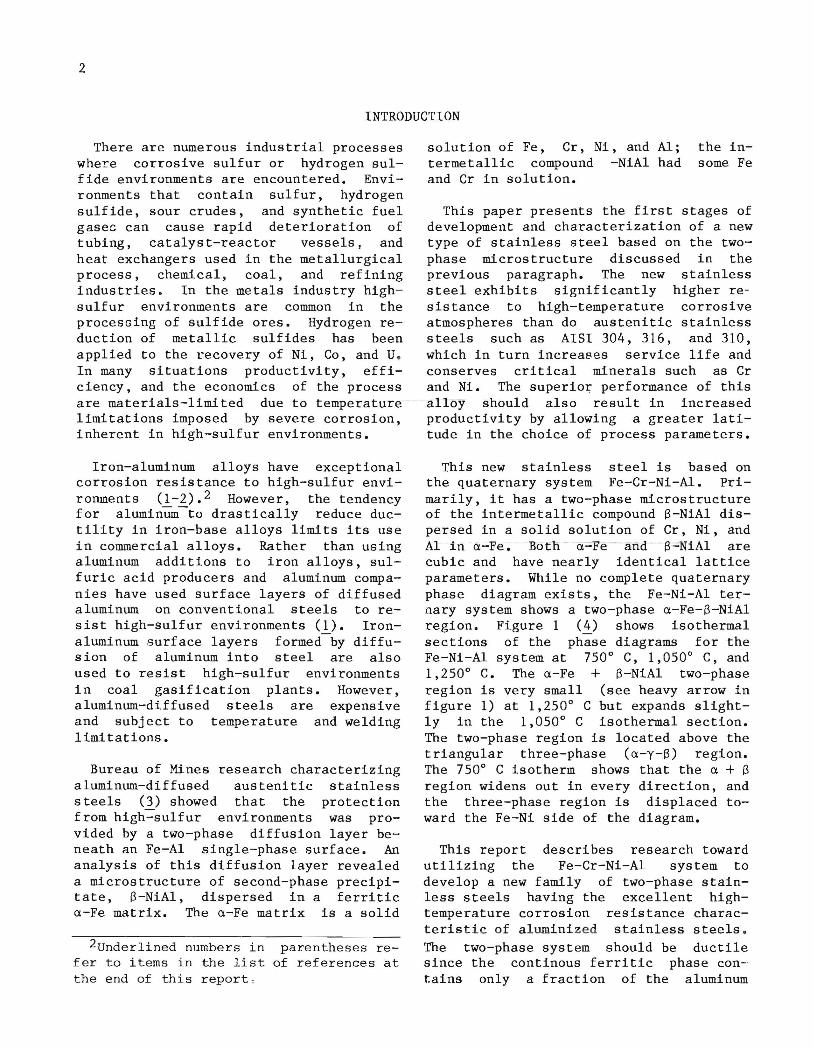
EVALUATION OF THE Fe-12Cr-jNi-4Al ALLOY
An 80-lb charge of the Fe - Cr - Ni - Al alloy was melted in a vacuum induction melting furnace and cast in a split steel mold with an exothermic hot top. The 80-lb charge was loaded 10 wt pct high on the Cr and Ai additions and 20 wt pct high on the Mn addition, based on past experience with similar alloy compositions. After casting, an X-ray examination indicated that the ingot was sound throughout, and after scalping and cleaning, the ingot was homogenized for 20 h at 1,22S o C. The ingot was forged and rolled at 1,100 0 C to sheet form using a 20-pct reduction per pass with intermediate reheating between each pass.
Prior to final reduction to specimen sheet thickness, the material was held at 7S0° C for 20 h to insure full precipitation and given a final 30-pct reduction to final thickness at 7S0° C. The final reduction was conducted at a 10-pct reduction per pass to break up any continuous grain boundary precipitation.
Chemical analysis of the ingot yielded the following composition:
Fe(bal) - 13.1Cr- 4.86Ni- 3.S9Al- 1.23Mn-
0.94Si-0.39Ti-0.019C.
Specimens were prepared for metallographic, SEM, and TEM examination; sulfidation testing; oxidation testing; and roomtemperature and elevated-temperature mechanical property evaluation.
METALLOGRAPHIC, SEM, AND TEM EXAMINATIONS
The microstructure of the nominal Fe-12Cr-SNi-4Al alloy is shown in figure 6 at magnifications of (A) X 400 and (B) X 1,400. A very fine uniform precipitate dispersion was achieved. The precipitates were difficult to fully resolve by optical metallography even at X 1,400. SEM photographs of the sample were obtained to resolve the individual precipitate particles. An SEM micrograph taken at X lS,OOO magnification and 30 kV is shown in figure 7. The size of the particles ranges from O.OS to 0.2S ~m, with an average length of approximately O.lS ~m (l,SOO A).
FIGURE 6. - Microstructure of nominal Fe-12Cr-5Ni-4AI alloy. A, At X 400; B, at X 1,400,

10
-. ..., 0 ...
~ .~
~:.') ,.~ ~
- \J 0 ~ J
l J ~ .' "')
# , :>
~ '-~ "')
" ;l .,1\ • :. ~J -.~ ~ • ''\
':' , ", J ......
~ :\ . ,
• (i , ) :-. •
~ u -)
;-) .-)
" , ")
'oJ '-
'} (') ..,
~) ""') ., ...
")
... ."' " )
FIGURE 7 .• Scanning electron micrograph (SEM) of Fe.12Cr·5Ni-4AI alloy (X 15,000).
Thin slices of the nominal Fe-12Cr-5Ni-4Al alloy were cut with a diamond saw and then chemically polishe d and thinned for study in the t r a nsmi s sion electron microscope (5) . A transmission elect r on micrograph i s shown in figu r e 8 . A finely dispersed second- phase precipitate of the ordered phase S-NiAl was revealed which was determined to have a B2(CsCl) superlattice structure. The semi coherent precipitates shown in figure 8 contain interfacial dislocations similar to those recently described for NiAl precipitates in Fe-19Cr alloys (6). Superlatticecentered dark field images corresponding to selected area electron diffraction patterns showed the precipitates to be ordered particles with a lattice parameter very close to the matrix. Again the precipitates averaged approximately 0.15 ~m (1,500 A) in length.
SULFIDATION RESISTANCE
The sulfidation resistance of the nominal Fe-12Cr-5Ni- 4Al alloy was compared
with t h a t o f thr ee conventiona l stainless s teels in a sulfur vapor plus steam atmosphere at 1,250° F . Three alloys were selected for comparison:
316 stainless s t eel (Fe-18Cr-12Ni- 2Mo).
304 stainless steel (Fe-18Cr-8Ni).
310 stainless steel (Fe-25Cr-20Ni).
Spe c imens 1/2 in by 6 in by specimen sheet thickness were prepared, and all surfaces were ground to a 240-grit metallographic finish. The specimens were weighed pr:tor t o t esting and after exposure to sulfur vapor plus steam and careful scale removal. The weight loss was conve rted t o a corrosion rate in mils per year. The effectiveness of the Fe-Cr-NiAl alloy in resisting sulfur environments is most dramatically demonstrated in table 4. The data are also plotted graphically in figure 9. The following conclusions can be drawn from the data:
1. Corrosion rates for types 304 and 316 s tainless stee l are four and five times greate r , respectively, than those for the Fe-Cr-Ni-Al alloy.
2. Corrosion rates for type 310 stainless steel are three times greater than those for the Fe-Cr-Ni-Al alloy.
316 304 310
TABLE 4. - Corrosion properties of Fe-Cr-Ni-Al alloy compared with those of commercial stainless steels in sulfur vapor with steam at 1,250° F
Corrosion rate after Alloy fixed duration test,
designation mpy 9 18 27
days days days stainless steel 66 27 19 stainless steel 63 19 15 stainless steel 52 15 12
Fe-Cr-Ni-Al •••••••• 14 5 4

11
FIGURE 8. - Transmission electron micrograph (TEM) of nominal Fe-12Cr-5Ni-4AI alloy;
precipitates are semicoherent (X 60,000).
The data indicate that small additions of AI can be successfully incorporated into this type of low-CrNi alloy to yield a low-cost stainless steel, and that significant advantages can be ga ined i n these hostile environments in terms of conservation of critical and strategic minerals.
OXIDATION RE SI STANCE
The oxidation res istance Cr-Ni-Al alloy was compared
of t he with
Fethat
of the same t hree commercial stainless steels plus a fourth commercial alloy , 29Cr- 4Mo, that has high Cr but contains no Ni. The cycl i c oxidation tests were carried out in static air at 700 0 C. Specimens 1 in by 1 in by specimen sheet thickness were pr epared to a 240-grit finish a nd weighed pr i or to testing and pe r i odica l l y t hroughou t t he tes t, which was curtailed af t er 400 h . Data a re p lo t t ed i n f i gur e 10 .

12
70
60
>. a. 50 E
w ~ 40 0:::
Z 310 stainless 0 30 steel
(J)
0 0::: 0::: 20 0 u
10
----0 O~~~----~--~----~--~
5 10 15 20 25 30 DURAT ION OF TEST, days
FIGURE 9. - Corrosion rate of Fe-12Cr-5Ni-4AI
alloy in sulfur vapor plus steam at 1,250 0 F com
pared with rates for some conventional stainless steels.
The nominal Fe-12Cr-5Ni-4Al alloy showed oxidation resistance markedly superior to that of types 304 and 316 stainless steels, which have 1-1/2 times the Cr content and approximately twice the Ni content, and was equivalent to that of type 310 stainless steel, which has twice the Cr and four times the Ni content. Oxidation was also superior to that of the 29Cr-4Mo alloy.
600 .---,---,----r---,----r---,---,---~
(\J
E
~ 400 :t.
Z « <:> f-I 200 <:> w ~
o o
/304 stainle ss
o slee l
'V--;;"--3 1-6- 5-1 a-i n-l-eS-S-1J
ste e l
t::. ;29Cr-4Ma
t::.~~-t::. t::.~~~-jt::..
0 - 0--- 0 --0-------- ~---------.-. .. o
10 0 200 30 0 40 0 "DURATI ON OF TEST, h
FIGURE 10. - Oxidation rate of Fe-12Cr-5N i-4AI
alloy at 700 0 C compared with rates for some com
mercial stainless steels.
The exceptional performance of the alloy again demonstrates the effectiveness of Al additions in achieving comparability with alloys of considerably higher Cr and Ni contents.
MECHANICAL PROPERTIES
Room-temperature and elevated-temperaperature mechanical properties and stress rupture properties of the Fe-Ni-Cr-Al alloy are compared with those of type 310 stainless steel in tables 5 and 6. The room-temperature yield strength of the Fe-Ni-Cr-Al alloy is considerably higher than that of type 310 stainless steel, indicating effective strengthening by the second-phase dispersion. The elongation at room temperature indicates that some compromise is necessary to sacrifice room-temperature strength to enhance ductility to the 10- to 25-pct elongation
TABLE 5. - Tensile properties of Fe-12Cr-5Ni-4Al alloy compared with those of type 310 stainless steel
Test Ultimate tensile Yield strength Elongation, temperature Alloy strength, (0.2-pct offset), pct
psi psi Room ......... Fe-Cr-Ni-Al 110,000 92,500 6
Type 310 95,000 45,000 45 7000 c ..... Fe-Cr-Ni-Al 24,000 14,000 34
Type 310 45,000 16,000 40 8000 c ....... Fe-Cr-Ni-Al 10,000 7,000 39
Type 310 28,000 12,000 40
TABLE 6. - . Stress rupture properties of Fe-Ni-Cr--AI alloy compared with those of type 310 stainless eteel
Test Stress, Rupture life, h temp, °c kg/in2 Fe-Cr-Ni-AI Type 310 6000 ••••• 30 50 200 700 •••••• 15 2 30
1/ 31 80 10 102 110
800 •••••• 6 3 30 4 21 100
rang.e. The yield strengths at 700° Care roughly equivalent, while at 800° C the s ti:ength of the Fe-Ni-Cr-Al falls off rapidly. It was evident that at 800° C the strengthening effect of the NiAI dispersion was largely ineffective.
13
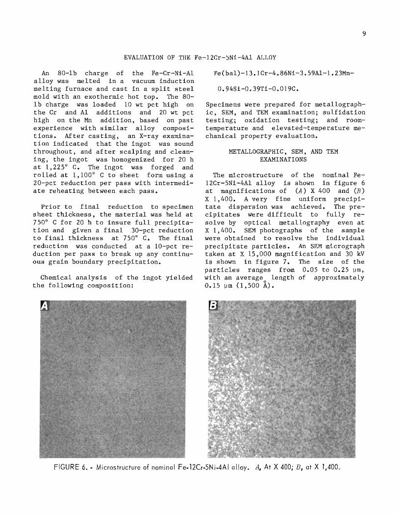
Specimens of the nominal Fe-12Cr-5Ni-4AI alloy, after rolling at 1,100° C, soaking at 750° C for 20 h, and a final rolling at 750° C, were heattreated to study the effect of testing temperature on elevated-temperature strength. Specimens were soaked at 600°, 700°, 800°, and 900° C and water-quenched to determine the high-temperature stability of the precipitatesc A series of micrographs, showing that solution of the B-NiAI phase begins between 700° C and 800° C, appear in figure 11. After soaking at 600° and 700° C prior to water quenching, the precipitate dispersion was unaffected. However, after 45 min at 800° C substantial solution of the B- NiAI precipitates had occurred, and after 30 min at 900° C,
Increasing sol ution heat
treatment temperature
8000 C
FIGURE 11. " T ensi Ie specimens of Fe-12Cr-5Ni-4AI alloy after soaking at various temperatures
prior to quenching (X 1,400).

14
complete re-solution of the precipitate dispersion had occurred. The decline in elevated- temperature strength at 800° C can thus be attributed to solution of the precipitate dispersion.
Stress rupture properties of the Fe-NiC1."··Al alloy were generally lower than those of type 310 stainless steel , again indicating that S-NiAI dispersion was not particularly effective in providing strength to 800° C.
To improve high-temperature strength, it is necessary to prevent complete resolution of the S-NiAI at 900° C.
A Geries of 46 compositions of Fe-NiCr-Al alloys was melted in the form of 100-g ingots. Aluminum was held constant at 4 wt pct, Ni was varied between 8 and 12 wt pct, and Cr was varied between 12 and 17 wt pct. Metallographic specimens were cut from each ingot and held at 600°, 700°, 800°, and 900° C for up to 20 h prior to water quenching 0 Figure 12 is a psuedo-phase diagram showing compositions where the a + S microstructure is stable to 900° C. Metallographic examination showed that some re-solution of the S-NiAI had occurred in these compositions, but sufficient S-NiAI remained in the form of fine dispersions to provide strengthening at temperature. This research will provide the basis for selection of second-generation compositions where the strengthening observed at room temperature should extend to elevated
12~--~----~--~----~
a+y+/3
I I
10 -u a. - 9 ~
.. z
8
7 a
6------I.-- --I.... _ _ ~----'
13 14 15 16 17 Cr, wt pet
FIGURE 12 •• Fe-4AI alloyswithvarying Crand
Ni contents showing compositions where the a + f3 structure is stable to 900 0 C.
temperature, matching or surpassing the mechanical properties of 310 stainless steel while retaining the superior hotcorrosion properties.
DISCUSSION, SUMMARY, AND CONCLUSIONS
A new concept for a sulfidation-resistant steel with aluminum additions was devised. Workable alloys with suitable microstructure were achieved, and a test composition of Fe-12Cr-SNi-4AI was selected to evaluate properties. While the composition selected was definitely preliminary, the property evaluation yielded a very promising combination of properties that can be summarized as follows:
1. Sulfidation and oxidation resistance were excellent.
2. Mechanical properties at room temperature indicated that the precipitate dispersion provides adequate strengthening, but compromises are in order to moderate strength and increase the roomtemperature ductility.
3. Precipitation hardening was not sufficiently stable to maintain the strength at elevated temperature. This was associated with solution of precipitates within the temperature range of interest, 600° C to 900° C. Preliminary

studies have indicated that an adjustment of the Cr and Ni levels can effectively increase the stability of the precipitates and should result in improved elevated-temperature strength.
4. A goal of surpassing the elevatedtemperature properties of type 310 stainless &teel has been set.
15
Overall, the concept appears viable, and the chances for a new low-cost, lowCr alloy for use in severe corrosion en-· vironments at temperatures to 800 0 C appear good. The goal of conservation of strategic and critical minerals (Cr and Ni) and the potential for improved productivity through the removal of materials limitations should both be furthered.
REFERENCES
1. Chemical Week. Aluminizing Steel To Slow High-Sulfur Corrosion. July 14, 1982, pp. 25-26.
2. McGill, W. A., and M. J. Weinbaum. Aluminium Diffused Steel Resist High Temperatures in Hydrocarbon Environments. Met. Prog., v. ll5, No.2, 1979, pp. 26-31.
3. Oden, L. L., McCune. Analysis Diffused Stainless 8629, 1982, 12 pp.
M. P. Krug, and R. A. of Vapor-AluminumSteels. BuMines RI
4. Brewer, L. , and Constitution of Ternary
S. G. Alloys.
Chong. Ch. in
Metals Handbook. ASM, Metals Park, OH, v. 8, 8th ed, 1973, pp. 393-394.
5. Murr, L. E., J. S. Dunning, and S. Shankar. NiAl Precipitation in Fe-12Cr-5Ni-4Al. Paper in Proceedings of the 41st Annual Meeting of the Electron Microscopy Society of America. San Francisco Press, Inc., 1983, p. 202.
6. Taillard, R., A. Pineau, and B. J. Thomas. The Precipitation of the Intermetallic Compound NiAl in Fe-19Cr Alloy. Mater. Sci. Eng., v. 54, 1982, p. 209.
INT.-BU.OF MINES,PGH.,PA. 27341