a study on use of polymeric waste materials in concrete ... · a study on use of polymeric waste...
TRANSCRIPT

A STUDY ON USE OF POLYMERIC WASTE MATERIALS IN
CONCRETE FOR ROAD PAVEMENTS
A Thesis submitted in partial fulfillment of the requirements for the Degree of Bachelor of
Technology in Civil Engineering
By
Nitesh Agrawal (111CE0498)
Rajanikanta Behera (111CE0591)
Under the guidance of
Prof. Mahabir Panda
Department of Civil Engineering
National Institute of Technology
Rourkela – 769008
Odisha
A STUDY ON USE OF POLYMERIC WASTE MATERIALS IN CONCRETE FOR ROAD PAVEMENTS
A Thesis submitted in partial fulfillment of the requirements for the Degree of Bachelor of
Technology in Civil Engineering
By
Nitesh Agrawal (111CE0498)
Rajanikanta Behera (111CE0591)
Under the supervision of
Prof. Mahabir Panda
Department of Civil Engineering
National Institute of Technology
Rourkela – 769008
Odisha

CERTIFICATE
This is to certify that the work in the thesis entitled “A STUDY ON USE OF POLYMERIC
WASTE MATERIALS IN CONCRETE FOR ROAD PAVEMENTS” submitted by Nitesh
Agrawal and Rajanikant Behera, students of NIT Rourkela, is an authentic work and has been
carried out by them under my supervision and guidance in partial fulfillment of the requirements
for the Degree of Bachelor of Technology in Civil Engineering, the Department of Civil
Engineering, National Institute of Technology, Rourkela.
Date: Prof. Mahabir Panda
Department of Civil Engineering
National Institute of Technology
Rourkela – 769008

ACKNOWLDEGEMENTS
It’s a great pleasure to express our deep sense of gratitude and respect to our supervisor Prof.
Mahabir Panda for his excellent guidance, suggestions and support throughout the project. We
feel extremely lucky to be able to work under the guidance of such a dynamic personality. We
also thank Prof. Shisir Kumar Sahu (The Head of the Department, Department of Civil
Engineering, NIT Rourkela) for his extreme support for the successful completion of this project.
Last but not the least, we extend our sincere thanks to all our friends at the Department of Civil
Engineering, NIT, Rourkela, for their help in every stage for the successful completion of this
project report.
Nitesh Agrawal (111CE0498)
Rajanikanta Behera (111CE0591)
4thYear B. Tech.
Department of Civil Engineering
National Institute of Technology
Rourkela - 769008

CONTENTS
Contents Page no.
Abstract 1
Chapter – 1
Introduction
1.1 General 1.1
1.2 Waste polyethylene and tires are a concern 1.4
1.3 Objective 1.4
Chapter – 2
Literature review
2.1 Role of polymer in pavement 2.1
2.2 Polymer fibers as an option to conventional reinforcement 2.1
2.3 Types of FRC 2.1
2.3.1 Synthetic fibers 2.2
2.4 Fiber properties 2.2
2.4.1 Ductility 2.3
2.4.2 Fracture Toughness 2.3
2.4.3 Other properties 2.4
Chapter – 3
Base materials
3.1 Basic material 3.1
3.1.1 Water 3.1

3.1.2 Cement 3.2
3.1.3 Fine aggregate 3.3
3.1.4 Coarse aggregate 3.4
3.1.5 Admixture 3.6
3.1.6 Fibers 3.7
3.2 Material preparation 3.7
3.2.1 Preparation of fibers 3.8
Chapter – 4
Experimental work
4.1 Methodology 4.1
4.2 Tests on Aggregates: 4.1
Abrasion resistance of aggregates: 4.1
Impact resistance of aggregates 4.2
Crushing resistance of aggregates 4.4
4.3 Mix design 4.5
4.4 Casting and curing 4.6
4.5 Test of concrete 4.7
Compressive strength test 4.7
4-Point bend test (2-Point load test) 4.10
Double shear test 4.17
Chapter – 5
Result analysis

5. Methodology 5.1
5.1 4-Point bend test 5.1
5.2 Double shear test 5.4
Chapter – 6
Discussion and Conclusion
6.1 Discussions 6.1
6.2 Conclusions 6.1
References 7.1

List of tables
Table Page no.
4.1: Test on aggregates 4.5
4.2: Mix design 4.6
4.3: Compressive strength of conventional concrete cubes 4.9
4.4: Compressive strength of fiber introduced concrete cubes 4.11
4.5: Flexural strength of conventional concrete beams 4.13
4.6: Flexural strength of fiber introduced concrete beams 4.13
4.7: Flexural strength gain and deflection reduction in fiber introduced
concrete beams
4.14
4.8: Load and deflection of conventional concrete and fiber introduced
concrete beams (M30)
4.15
4.9: Load and deflection of conventional concrete and fiber introduced
concrete beams (M35)
4.16
4.10: Load and deflection of conventional concrete and fiber introduced
concrete beams (M40)
4.16
4.11: Shear strength of conventional concrete beams 4.20
4.12: Shear strength of fiber introduced concrete beams 4.21
4.13: Shear strength gain and deflection reduction in fiber introduced
concrete beams
4.22

4.14: Load and deflection of conventional concrete and fiber introduced
concrete beams
(M30)
4.22
4.15: Load and deflection of conventional concrete and fiber introduced
concrete beams
(M35)
4.23
4.16: Load and deflection of conventional concrete and fiber introduced
concrete beams
(M40)
4.24
5.1: Theoretical and experimental deflection of conventional concrete 5.2
5.2: Theoretical and experimental deflection of fiber introduced concrete 5.3
5.3: Comparison of theoretical and experimental deflection 5.3
5.4: Theoretical and experimental deflection of conventional concrete 5.4
5.5: Theoretical and experimental deflection of fiber introduced concrete 5.5
5.6: Comparison of theoretical and experimental deflection 5.6

List of tables
Figure Page no.
1.1: Steel fiber 1.2
1.2: Polypropylene fiber 1.2
1.3: Polyethylene fiber 1.3
3.1(a): OMFED Polyethylene 3.9
3.1(b): Shredded polyethylene 3.9
3.2: Steel wires taken out and tire cut in 30mm x 6mm 3.9
4.1(a): Compressive strength test 4.9
4.1(b): Compressive strength test 4.9
4.2(a): 4 Point bend test 4.12
4.2(b): 4 Point bend test 4.12
4.2(c): 4 Point bend test Load vs Deflection for M30 concrete 4.17
4.2(d): 4 Point bend test Load vs Deflection for M35 concrete 4.18
4.2(e): 4 Point bend test Load vs Deflection for M40 concrete 4.18
4.3(a): Double shear test 4.20
4.3(b): Double shear test Load vs Deflection for M30 concrete 4.25
4.3(c): Double shear test Load vs Deflection for M35 concrete 4.25
4.3(d): Double shear test Load vs Deflection for M40 concrete 4.26

Abstract
Concrete is strong in compression but weak in tension and brittle also. Cracks also start forming
as soon as the concrete is placed. These 3 drawbacks don’t permit the use normal concrete in
pavements as they lead to lack of ductility along with fracture and failure. These weaknesses in
concrete can be mitigated by using fibers as reinforcement in the concrete mix. Waste materials
in the form of polyethylene and tires cause environmental pollution which leads to various health
problems. Polyethylene and waste tires can be recycled and used effectively in the concrete as
reinforcement in the fiber form. Polyethylene is a synthetic hydrocarbon polymer which can
improve the ductility, strength, shrinkage characteristics etc. This paper deals with the effects of
addition of polyethylene fiber on the properties of concrete. Polyethylene and tire fibers were cut
into the size of 30mm x 6mm and they were used 1.5% each by volume. Grade of concrete used
were M30, M35 and M40. IRC 44:2008 was followed for the design of concrete mix. In this
study, the results of the Strength properties of Polyethylene fiber reinforced concrete have been
presented. 4 point bending test and double shear test were performed in the laboratory for flexure
and shear strength determinations. There was seen an increase of 18% in the 28 day compressive
strength along with an increase of 39% in flexure and 32% in shear strength. 22% decrease in 4
point bending test and 36% decrease in double shear test in deflection was found out from the
experiments. Theoretical analysis of deflection was carried out by the help of energy methods.
Practical values were verified with the theoretical values within the permissible limits. Finally it
can be concluded that polyethylene and tire can be used effectively in reinforced cement
concrete.

[CHAPTER – 1]
[INTRODUCTION]

1.1 | P a g e
CHAPTER – 1
INTRODUCTION
1.1 General For a developing nation such as India, road networks play a crucial role in providing a durable
and comfortable surface for vehicles. Pavements are mostly made using bitumen. However, in
certain situations concrete pavements are also preferred. Many additives have been explored for
beneficial use of concrete as a paving material. A recent research has shown that fiber reinforced
concrete (FRC) can be used for the construction of pavements as it is found to be very good in
strength and it also exhibits other desirable properties [25]. The definition of FRC given by ACI
Committee 544 is “fiber reinforced concrete is a concrete which is made of cements containing
fine and coarse aggregates along with water for obtaining cementious properties and
discontinuous fibers” [1]. The fibers used are of various types such as steel fibers, polymer or
natural fibers etc. [5 and 6]. As said earlier, fiber reinforced concrete is that form of concrete
where fibers are put into the concrete as reinforcement in order to increase the strength
characteristics and other mechanical properties of the concrete. Fiber reinforced concrete is not
just provided for local strengthening in tensile region but it is provided for obtaining a gain in
compression and tension along with reduced deflections and shrinkage and increased ductile
property [3, 4, 13, 14, 15, 16 and 25].
Apart from the above mentioned properties, polymeric fibers also help in corrosion reduction.
Commonly, Recron 3s, polyester and polypropylene have been used for the purpose of FRC.
Recently, other forms of recycled fibers like plastic, disposed tires, carpet waste and wastes from

1.2 | P a g e
textile industry are also being adopted for the same purpose. Basic function of these fibers is to
act as crack arresters. Fibers help in resisting the minor cracks and would not let them grow into
macro cracks. Hence, the material transforms into a material with improved ductility and
toughness to failure [4, 13, 14 and 16].
Fig 1.1 Steel fiber (Source: Google images)
Fig 1.2: Polypropylene fiber (Source: Google images)
1.3 | P a g e
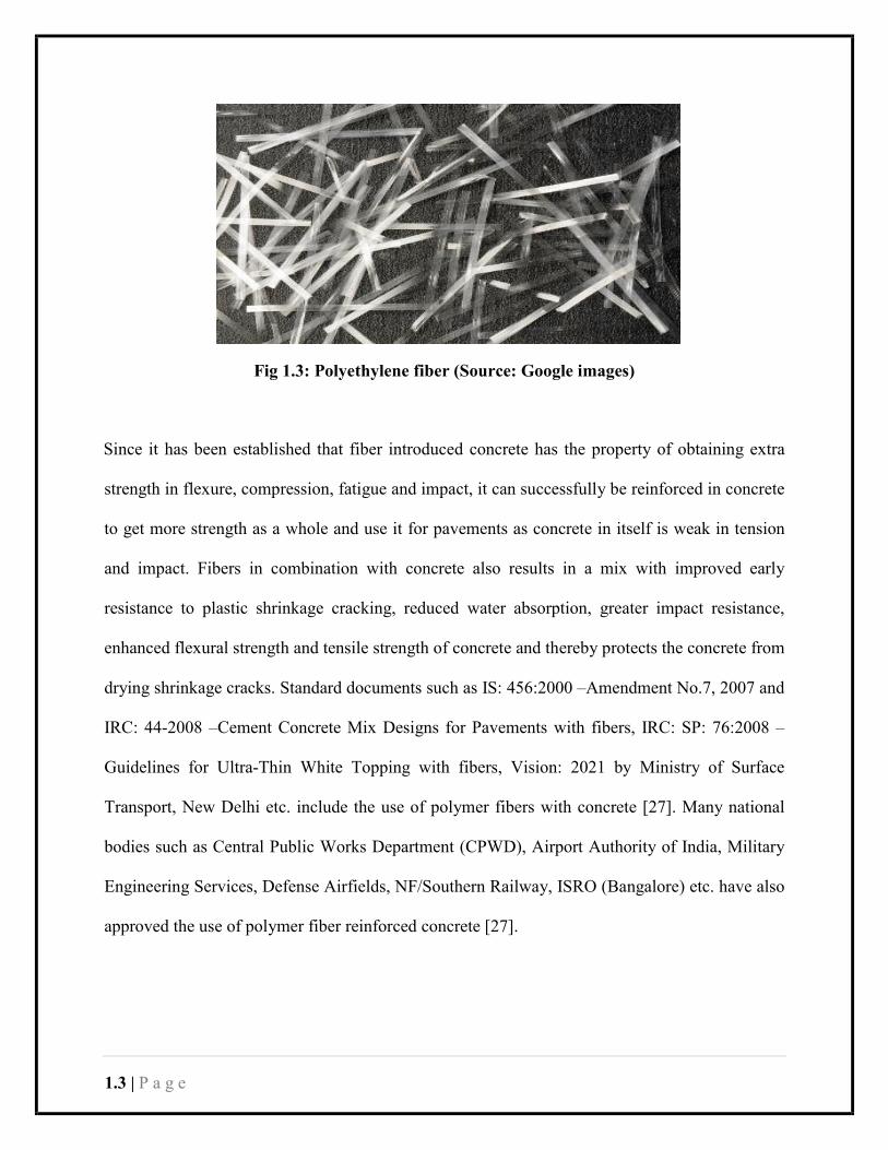
Fig 1.3: Polyethylene fiber (Source: Google images)
Since it has been established that fiber introduced concrete has the property of obtaining extra
strength in flexure, compression, fatigue and impact, it can successfully be reinforced in concrete
to get more strength as a whole and use it for pavements as concrete in itself is weak in tension
and impact. Fibers in combination with concrete also results in a mix with improved early
resistance to plastic shrinkage cracking, reduced water absorption, greater impact resistance,
enhanced flexural strength and tensile strength of concrete and thereby protects the concrete from
drying shrinkage cracks. Standard documents such as IS: 456:2000 –Amendment No.7, 2007 and
IRC: 44-2008 –Cement Concrete Mix Designs for Pavements with fibers, IRC: SP: 76:2008 –
Guidelines for Ultra-Thin White Topping with fibers, Vision: 2021 by Ministry of Surface
Transport, New Delhi etc. include the use of polymer fibers with concrete [27]. Many national
bodies such as Central Public Works Department (CPWD), Airport Authority of India, Military
Engineering Services, Defense Airfields, NF/Southern Railway, ISRO (Bangalore) etc. have also
approved the use of polymer fiber reinforced concrete [27].

1.4 | P a g e
1.2 Use of Waste polyethylene and tires Plastics are very strong and non-biodegradable in nature. The chemical bonds in plastics make it
extremely sturdy and impervious to ordinary common techniques of degradation. The daily use
of plastics has increased very rapidly and it has become a common habit of people to just throw
out the plastic and causing environmental pollution. Over 1 billion tons of plastic have been
produced since 1950s, and the same is likely to remain as such for many years [28]. These wastes
get mixed with MSW or they are simply thrown causing nuisance to the society. There is a big
need of recycling of the plastics as well waste tires because we don’t have any other option of
disposing them without securing environment from pollution. For example, there are two
processes for the disposal of wastes: land filling and incineration. If the wastes are simply
dumped, they cause soil and water pollution and if they are incinerated, they cause air pollution.
Hence, there is a need to recycle the wastes into something useful which will not hamper the
environment and the process in which it is used [28].
1.3 Objective The present work is aimed at using two polymeric waste materials, such as polyethylene and tire
fibers as reinforcement in concrete pavement. The basic objective of this work is to assess the
advantages of using such waste materials such as increase in compressive, flexure and shear
strength and decrease in deflection characteristics of the resultant concrete and also the
determination of the deflection in the laboratory testing then its comparison to the theoretical
deflection and check whether the errors are in the permissible limits of 20%.
The main goal of the study is to utilize waste materials polyethylene and tire to achieve greater
concrete strength properties in order to recycle them into something very useful and helping in
reducing the environmental impact that the both of them have.

[CHAPTER – 2]
[LITERATURE REVIEW]

2.1 | P a g e
CHAPTER – 2
LITERATURE REVIEW
Fiber reinforced concrete (FRC) is made by mixing polymer fibers into a conventional concrete
mix. The definition of FRC given by ACI Committee 544 is “FRC is a concrete which is made of
cements containing fine and coarse aggregates along with water for obtaining cementious
properties and discontinuous fibers.” [1]
2.1 Role of polymer in pavement
There is a need of improvement in the quality of the pavements as the steady increase of wheel
loads, change in climatic conditions, tire pressure & daily wear and tear adversely affect the
performance of vehicles over the pavement [28].
Synthetic polymer fibers can be used to overcome the above mentioned problems which are
faced in daily life. Modifying the concrete with the polymers can improve the crack arresting
capability, fatigue life and many other mechanical prospects of pavement [28].
2.2 Polymer fibers as an option to conventional reinforcement
Fibers are known to have been used initially by the ancient Egyptians back in 1500 B.C. These
people used the hair of animals as reinforcement for not only mud bricks but walls in housing
also [6]. Various studies have provided an overview of the developmental stages of Fiber
Reinforced Concrete. In the 1960s, polymer fibers were taken seriously for using in
reinforcement concrete and it then picked its momentum from then [5].
2.3 Types of fiber reinforced concrete
ACI has divided fiber reinforced concrete into 4 categories namely SFRC, GFRC, SNFRC and

2.2 | P a g e
NFRC. Here SFRC means steel fiber reinforced concrete, GFRC stands for glass fiber reinforced
concrete, SNFRC is synthetic fiber reinforced concrete and NFRC is an acronym for natural fiber
reinforced concrete. There are also discussed many theoretical and practical insights about
different design applications and physical and mechanical properties [1]. Another method of
classification was adopted by Cement and Concrete Institute in which fibers are divided into the
following types, glass fibers, steel fibers, synthetic fibers and natural fibers [2].
2.3.1 Synthetic fibers
Synthetic fibers include polyethylene, polypropylene, acrylic, carbon, aramid, nylon, polyester
etc [2]. Synthetic fibers can be further classified into macro-fibers and micro-fibers. Both of
these subtypes have different properties with respect to each other. We have used polyethylene
and tire in the form of macro-fibers as the reinforcement. Chosen size is 30mm x 6mm.
2.4 Fiber properties
The effect of all types of fibers has been studied by many researchers. They have studied the
physical properties along with mechanical properties of concrete. But there hasn’t been done
much research on polyethylene fiber reinforced concrete and waste tire fiber concrete. The
knowledge regarding these fibers as a reinforcement in concrete is limited.
The way fibers are distributed in the concrete significantly affects the properties of FRC. It was
found out in a study that the fibers which are of higher volume fractions and longer in size
showed balling at the time of mixing. This leads to stiffening of the concrete paste. When the
volume fractions of fibers are increased, it further leads to a reduction in workability. This will in
turn have an impact on the mechanical properties of concrete and its quality [6]. Synthetic fibers
are used mainly to control cracking and plastic shrinkage [11, 12, 13 and 14].

2.3 | P a g e
2.4.1 Ductility
Ductility can be defined as “the ability of material to undergo large deformations without rupture
before failure”. It is considered a good warning indicator before failure [3]. When fibers are
induced into the conventional concrete, they increase the ductility of the concrete [3]. High
damage tolerant beam-column joints can be achieved by using high performance fiber reinforced
cement composites. When this joint is constructed with 1.5% by volume of ultra-high molecular
weight polyethylene fibers tend to show very good strength characteristics along with reduction
in deformation [15].
2.4.2 Fracture Toughness
Under a static, dynamic or impact load, the energy absorption capacity of material is measured
through fracture toughness [4]. Post-cracking behavior of concrete beam is checked at mid span
by determining the deflection for fracture toughness. There have been made many studies over
the effects of toughness on fiber type, dosage, properties, and bonding conditions. These affects
can further be found in ACI 544 and other literatures are also available [13, 14 and 16].
Conventional reinforcement such as steel is provided in the concrete because it fails in tension.
Similarly due to very good ductile and toughness properties fibers can also be induced into the
concrete as reinforcement in order to improve the tensile resisting capacity of the concrete by
redistributing the stress concentration [17]. Studies done on concrete to understand this stress
redistribution result that crack surface is the surface in the concrete matrix where fibers restrain
cracks. There are 3 regions of stress redistribution which are - traction free zone where much
larger crack openings are found with respect to the other zones, fiber 6 bridge zone where
frictional slip of fiber is responsible for stress transfer and micro-macro crack growth zones
where interlock between aggregates is found to have transfer the stress [18].

2.4 | P a g e
2.4.3 Other properties
Fiber reinforcement causes reduction in early age shrinkage as well as the drying shrinkage in
concrete. Fiber in a concrete captures the micro cracks and prevent it from turning into a macro
crack even at the very early ages [12, 19, 20, 21, 22, 23 and 24]. Concrete when reinforced with
polyethylene fibers in 2 to 4% by volume shows a linear deflection curve up to the first crack
formation but it transfers the load to the fibers until the fibers break [2].
There have been shown increase in the compressive strength upto 20% and flexural strength upto
40% at 28 days when fiber induced are steel or polypropylene [25]. Further when waste tire
fibers are used in the concrete, under Impact loading, resistance is shown for cracking. The
reinforced concrete thus made, shows increase in the toughness of the concrete. The toughness of
waste tire modified concrete is found to be much larger than conventional concrete. Hence its
energy absorption capacities are much larger compared to the normal concrete. Further, the
failure occurred in ductility rather than in brittleness. Waste tire fibers have been found to have
capture the cracks when minor impacts are made on concrete. Waste tires also contribute towards
ductility in case of compression failure [26].
Casting of concrete cubes and beams for compression and flexure tests were according to the IS
456:2000 [7]. Further, mix design was followed as per the IRC 44:2008 in order to maintain the
quality of the pavements [8]. Compression testing machine was used for determining
compressive strength. For determining flexural strength, 4 point bending test and double shear
test were carried out [9]. Deformations were calculated using the practical investigation while
theoretical analysis was also compared. Energy methods are helpful in calculating deformation
formula for theoretical comparisons. Both formulas of deflection for 4-point bend test and double
shear test were calculated using the Castigliano’s first theorem [10].

[CHAPTER – 3]
[BASE MATERIALS]

3.1 | P a g e
CHAPTER – 3
BASE MATERIALS
3.1 Basic materials
The basic materials which compose concrete are:
1. Water
2. Cement
3. Fine aggregate
4. Coarse aggregate
5. Admixture
In case of polymer fiber reinforced concrete fibers are added. For this experiment 2 types of fiber
are chosen. The fibers to be used in the concrete mix are:
1. Polyethylene fiber
2. Tire (Nylon) fiber
Both fibers to be used in concrete matrix will be made from the waste materials. The wasted
pouches of OMFED milk will be used for making the polyethylene fiber whereas wasted tire will
be used to prepare nylon fiber.
3.1.1 WATER
Water is the most important material in concrete. It performs the following roles in concrete matrix:
1. It gives cement the adhering property. The quality, quantity, stability and rate of
formation of the adhesive material that binds the aggregates depend on the quality and
quantity of water added.

3.2 | P a g e
2. It also controls the workability of concrete. The more the water content (up to certain
limit) the more is the workability.
3. The mechanical properties of hardened concrete as compressive, flexural strength and
toughness also depend on hydration products of cement and there by depend on water
content.
4. The plasticity of concrete depends on the water content.
5. Water is also needed for curing of hardened concrete to help concrete acquire its required
strength.
3.1.2 CEMENT
Cement is a material which when combined with water exhibits cohesive and adhesive properties
that helps in holding the aggregates together to form a concrete mass. It is also called as
hydraulic cement as it gets its adhering property in an exothermic hydration process and forms a
water resisting material.
There are different types of cement. Some common types of cement are:
Ordinary Portland Cement (OPC)
It is a normal cement made by burning calcareous (Calcium carbonate) and argillaceous (Clay)
together at a very high temperature and then grinding the resulting calcined product known as
clinker with a minute amount of gypsum (for quicker hardening) into fine powder.
There are three grades of OPC available:
1. 33 grade OPC (follows IS 269)
2. 43 grade OPC (follows IS 8112)
3. 53 grade OPC (follows IS 12269)

3.3 | P a g e
The numbers 33, 43 and 53 represent the 28 days compressive strength of a standard cement sand
mortar. This cement is very commonly used in normal concrete constructions.
Portland Slag Cement (PSC)
This cement is made nearly as the same process as OPC, but in PSC clinker is grinded with slag
from blast furnace instead of gypsum. This cement follows IS 455:1989. This cement has
sulphate resistance property and is used where structure is exposed to adverse environmental
conditions.
Portland Pozzolana Cement (PPC)
Portland pozzolana Cement (PCC), conforming to IS: 1489, is a combination of fly-ash (from
thermal power plant) with clinker and gypsum. Pozzolana cement is prepared by grinding
Portland cement clinker with pozzolana. This type of cement is largely used in marine structure.
3.1.3 Fine Aggregate
Regular sand is generally used as the fine aggregate. In some cases quarry dust or dust from stone
crushers are also used as fine aggregate. It contributes to a major portion of concrete matrix. Both
natural and artificial sand can be used as fine aggregate. The roles of sand in concrete matrix are:
1. It fills up the void space between coarse aggregate.
2. It has a good contribution towards the workability of concrete.
3. It reduces the various forms of cracking in concrete.
4. It also reduces the shrinkage of concrete during drying process.
5. It accelerates the hardening process of concrete.
6. It helps in formation of sillicates which is a major part of hardened concrete.

3.4 | P a g e
But to be used effectively in concrete sand should possess certain qualities. The basic
requirements of sand to be used in concrete are:
1. It should be strong and durable.
2. It should be free from any kind of vegetation or organic matter.
3. In must not contain silt or clay in any form.
4. Sand mustn’t be hygroscopic in nature.
5. It should be chemically inert.
6. The size of the sand must be between 75microns to 4.75mm. That means it must
completely pass through IS 4.75mm sieve and completely retained on IS 75 micron sieve.
3.1.4 Coarse Aggregate
It is generally comprises of crushed stones like granite. Sometimes gravel or broken bricks are
also used as coarse aggregates. Coarse aggregate occupy the most part of the concrete matrix and
contribute toward weight and strength of the hardened concrete.
There are various types of coarse aggregate. Some commonly used type of coarse aggregates are:
A. Granite aggregates
Granite aggregates are crushed form of granular hard rock. The granite rock comes from
hardened magma erupted to the surface. Some of its properties has made it much popular
like it is highly solid (grade 1400 – 1600), frost resistant and possess less porosity.
Granite aggregate is composed of particles of various dimension. A sample of typical
granite aggregate composed of the following:
1. Granite sand: - The fraction of granite aggregate that has a dimension between 0 - 3
mm is called granite sand. It is generally used to increase friction and for deicing.
These are also used for decoration purposes.

3.5 | P a g e
2. Small chips: - The fraction of granite aggregate possessing a dimension between 3 –
10 mm are categorized under small chips. This fraction is commonly used for slab
construction.
3. Chips: - These have a dimension of 5 – 10 mm and is the most popular fraction. This
fraction of granite is used in general constructions like buildings, bridges, roads,
fillings, drainage structures etc. The more the portion of aggregates of this fraction in
concrete, the stronger the concrete is. However it is used generally for surfacing or
shortcreting applications.
4. Granules: - Aggregates under this category possess a dimension between 10 – 20mm
and are commonly used for paving operations, road constructions. Aggregates of this
fraction provide the most adhesion in the mixture. Percentage wise this is the most
used fraction.
B. Gravel aggregate
These aggregates are generally formed by crushing of natural stone or quarried rock.
These aggregates exhibit lesser strength than granite aggregate but are cheaper than them.
These types of aggregates are used in foundations. There are two types of gravel
aggregates.
Those are:
1. Scrabbled stone: - Crushed form of regular stone.
2. Pebbles: - Rounded stones generally found in river beds or coastal areas.
C. Lime aggregate
These are also called as dolomite aggregate. These are rarely used for any construction
process. The basic component of the lime aggregate is sedimentary limestone.

3.6 | P a g e
D. Secondary aggregates
Secondary aggregates come from crushing of demolition waste – concrete, brick or
asphalt. The main advantage of these types of aggregates are low cost. The cost of
secondary aggregates are half of the primary ones and can be prepared in the same
method.
3.1.5 Admixtures
The admixture is a chemical compound mixed with other ingredients of concrete before or
during mixing to make concrete achieve certain required properties.
Chemical admixtures are generally used for following reasons:
1. Reduce the cost of construction.
2. Modify properties of hardened concrete.
3. To retain quality of mix during transportation and placing.
4. Achieve certain properties after or before time.
There are mainly five classes of admixture:
A. Water reducing admixture: - These are generally used to reduce the water content of the
concrete mix. The admixtures can reduce the water content by 5 – 10%. By reducing the
water cement ratio concrete mix with higher strength can be achieved without increasing
the cement content and thus making the process economical.
B. Accelerating admixtures: - These admixtures are used to help concrete gain its strength
earlier. It reduces the initial strength development time and thereby time for curing. These
admixtures are preferable for concrete construction where early strength is required or in
cold climates.

3.7 | P a g e
C. Retarding admixtures: - These admixtures slow down the setting rate of concrete. These
are generally used in hot climate concrete construction to overcome the effect of
temperature to make concrete set fast. It also can be used in case of highly reinforced
structures to make sure that concrete is placed in homogeneous manner before it gains its
early strength and settle.
D. Inhibitors: - Inhibitors are used to protect the concrete structure in harsh environmental
condition. It is generally used when the concrete structure is exposed to chemical attacks
or saline condition etc. These admixtures produce a protective film over the concrete
structure to inhibit the reaction of the chemicals with concrete or the reinforcements
inside.
E. Super-plasticizers: - Popularly known as plasticizers, these admixtures can reduce the
required water content of concrete by 15 – 30%. But keep the concrete flow able enough
to be placed easily in highly reinforced structures. Effect of these admixtures last only for
30 – 60 minutes but help in achieving high strength.
3.1.6 Fibers
These are short discrete materials, may be metallic or polymeric, used as composing
reinforcement for concrete structures. These are mixed with other components of concrete to
form the matrix and add certain properties to it.
These are generally used to:
1. Improve tensile strength
2. Increase impact, crushing and abrasion resistance.
3. Increase flexural and shear strength.

3.8 | P a g e
4. Reduce the effect of temperature change on concrete.
Polymer fibers are corrosion resistant and can be used in saline environment.
3.2 Material preparation:
The materials used in the concrete mix are:
1. 53 grade OPC.
2. Zone – iii sand as fine aggregate.
3. 10mm and 20mm coarse aggregate.
4. Sikament – 170 admixture
5. Polyethylene fiber
6. Tire fiber
The aggregates of different grade to be used for preparing concrete mixes are sieved through
different IS Sieves and they are kept in different containers with proper marking.
3.2.1 Preparation of fibers
The polythene used in OMFED milk packets is used as raw material for preparation of the fiber.
These polythene packets are collected; they are washed and cleaned by putting them in hot water
for 3- 4 hours. They are then dried.
Similarly waste tires are collected. The steel wires inside them are striped out of the tires. They
are washed in hot water and then dried.
The dried polyethylene packets and the tires are cut into pieces of size 30mm x 6mm size. This is
to ensure that when the fibers are mixed with the cement and aggregate the mixing will be proper
and the fibers will be randomly distributed over the concrete matrix evenly.

3.9 | P a g e
Figure 3.1(a): OMFED Polyethylene used Figure 3.1(b): Shredded polyethylene
Figure 3.2: Steel wires taken out (left) and tire cut in 30mm x 6mm (right)
Certain properties of materials used:
1. Specific gravity of cement = 3.04
Grade of cement = OPC 53
2. Specific gravity of fine aggregate = 2.6
Zone of sand = Zone – iii

3.10 | P a g e
3. Specific gravity of coarse aggregate = 2.7
4. Dimension of fibers = 30mm x 6mm Specific gravity of polyethylene = 0.94
Specific gravity of tire = 1.14
The above data is used for mix design and batching of material to prepare concrete of required
characteristic strength.

[CHAPTER – 4]
[EXPERIMENTAL WORK]

4.1 | P a g e
CHAPTER – 4
EXPERIMENTAL WORK
4.1 Methodology
To study the various parameters of polymeric fiber reinforce concrete that affect the service life of
a pavement with minimal maintenance, the following experiments are needed to be carried out:
1. Test of aggregates
a. Abrasion resistance of aggregates
b. Impact resistance of aggregates
c. Crushing resistance of aggregates
2. Test of concrete
a. Physical inspection of concrete
b. 28 day compressive strength test
c. Flexural strength test
d. Shear strength test
The flexural strength test to be conducted is 2-point load test (4-point bend test) and the shear
strength test to be conducted is double shear test.
4.2 Tests on Aggregates
Abrasion resistance of aggregates
The Los Angeles abrasion test is conducted to calculate the abrasion resistance of coarse aggregate.
Procedure
I. Aggregates dried in oven at 105 - 110 °C to constant weight conforming to any one of the
grading. E.g. 1250 gm of 40-25 mm, 1250 gm of 25-20 mm, 1250 gm of 20- 12.5 mm,
1250 gm of 12.5-10 mm with12 steel balls.
II. Aggregate weighing 5 kg is placed in cylinder of the machine (W1).

4.2 | P a g e
III. Machine is rotated @ 30- 33 rpm for 500 revolutions.
IV. After 500 complete revolutions machine is stopped and complete material is taken out
including dust.
V. Then the complete material is sieved through 1.7 mm sieve.
VI. Then the retained mass is washed thoroughly, oven dried for 24 hours and then weighed
(W).
VII. So the weight of the mass passing = W1 – W = W2.
VIII. Then the abrasion resistance is calculated in terms of Los Angeles abrasion value (LAAV).
LAAV = (W2 / W1) x100
Where W2 = Weight of fines passing 1.7 mm
W1 = Weight of the sample
In this experiment
Weight of the sample = W1 = 5000gms
Weight of fines passing 1.7 mm = W2 = 1180gms
So LAAV = W2x100 / W1
= 1180 x 100/5000
= 23.6%
Impact resistance of aggregates
The Impact value test is conducted to measure the resistance of the aggregate towards impact
load. The impact test machine is used to determine the aggregate impact value of coarse
aggregate as per IS 2386 Part IV - 1963 -Methods of test for aggregates.
Procedure
I. Aggregate passing through 12.5 mm IS sieve and retained on 10 mm sieve is taken.

4.3 | P a g e
II. The aggregates are filled in the cylindrical measure in 3 layers by tamping each layer by
25 blows.
III. Excess aggregates are stroke off using the tamping rod as a straight edge.
IV. The net weight of aggregate in the measure is (W1).
V. The hammer is raised to height of 38 cm above the upper surface of the aggregates in the
cup and is allowed to fall freely on the specimen.
VI. After subjecting the test specimen to 15 blows, the crushed aggregate is sieved through IS
2.36 mm sieve.
VII. The fraction passing through IS 2.36 mm sieve is weighed (W2).
VIII. The impact resistance of the aggregates were expressed in terms of impact value.
Impact value = (W2 / W1) x100
Where W2 = Weight of fines passing 2.36 mm
W1 = Weight of the sample
In this experiment
Weight of the sample = W1 = 327gms
Weight of fines passing 2.36 mm = W2 = 71.3gms
So Impact value = W2x100 / W1
= 71.3 x 100/327
= 21.8%
Crushing resistance of aggregates
The Crushing value test is conducted to measure the resistance of the aggregate towards crushing
load.

4.4 | P a g e
Procedure
I. Aggregates passing 12.5 mm and retained on 10 mm are selected for this test.
II. 3.25 kg of the sample is taken and filled in the cylindrical measure in 3 layers, tamping each
layer 25 times.
III. After leveling the aggregates at the top surface the test sample is weighed (W1).
IV. The cylinder is now placed on the base plate.
V. The cylinder with the test sample and plunger in position is placed on compression
machine.
VI. Load is applied at a rate of 4 tons per minute up to 40 tons.
VII. The crushed aggregate is taken out and sieved through 2.36 mm IS sieve.
VIII. The materials passing through 2.36mm sieve is weighed (W2).
IX. The crushing resistance of the aggregate is then expressed in terms of crushing value.
Crushing value = (W2 / W1) x100
Where W2 = Weight of fines passing 2.36 mm
W1 = Weight of the sample
In this experiment
Weight of the sample = W1 = 353gms
Weight of fines passing 2.36 mm = W2 = 75.2gms
So Impact value = W2x100 / W1
= 75.2 x 100/353
= 21.3%
The experimental data is tabulated in table 4.1.

4.5 | P a g e
Table 4.1: Test on aggregates
L.A. ABRASION TEST IMPACT VALUE TEST CRUSHING VALUE TEST
1. Maximum value
allowed in fiber
introduced concrete =
30%
2. Test results on average
= 23.6%
1. Maximum value
allowed in fiber
introduced concrete
= 45%
2. Test results on
average = 21.8%
1. Maximum value
allowed in fiber introduced
concrete = 30%
2. Test results on average
= 21.3%
4.3 MIX DESIGN
The proportion of concrete mix is to be designed to ensure the workability of concrete and to make
the concrete possess the required strength, toughness and durability at the hardened condition.
The design mixes M30, M35 and M40 are carried out in accordance to codes IRC 44:2008.
The specifications of material used are
1. Cement :- OPC 43 grade
2. Fine aggregate :- Zone 3
3. Coarse aggregate :- Crushed rock (10mm and 20mm)
4. Admixture :- Plasticizer
a. The water cement ratio for design was chosen in between 0.4 to 0.45.
b. The coarse aggregates 10mm and 20mm are used in ratio 90 to 10.

4.6 | P a g e
c. In case of fiber introduced concrete, the polyethylene fibers and tire fibers each are used in 1.5%
v/v of concrete mass.
The design mix proportion is shown in the table 4.2
Table 4.2: Mix design
GRADE OF
CONCRETE
WATER
CEMENT
FINE
AGGREGATE
COARSE
AGGREGATE
(10mm)
COARSE
AGGREGATE
(20mm)
ADMIXTURE
M30 0.45 1 2.1 3.06 0.34 0.019
M35 0.43 1 1.6 2.7 0.3 0.022
M40 0.4 1 1.8 2.7 0.3 0.023
Specific gravity of polyethylene = 0.94
Specific gravity of tire (without steel wires) = 1.14
So
For cubes of size 150mm x 150mm x 150mm
I. Polyethylene fiber used = 47.56gms
II. Tire fiber used = 57.65gms
For beams of size 500mm x 100mm x 75mm
I. Polyethylene fiber used = 64.125gms
II. Tire fiber used = 52.875gms
4.4 Casting and curing
Standard sized cubes (150mm x 150mm x 150mm) are casted for compression test of concrete.
The beams casted are however different than standard size. The beams are casted with dimension

4.7 | P a g e
500mm x 100mm x 75mm.
Samples casted:
A. Cubes
I. 3 numbers of M30 conventional concrete
II. 3 numbers of M35 conventional concrete
III. 3 numbers of M40 conventional concrete
IV. 3 numbers of M30 fiber introduced concrete
V. 3 numbers of M35 fiber introduced concrete
VI. 3 numbers of M40 fiber introduced concrete
B. Beams
I. 6 numbers of M30 conventional concrete
II. 6 numbers of M35 conventional concrete
III. 6 numbers of M40 conventional concrete
IV. 6 numbers of M30 fiber introduced concrete
V. 6 numbers of M35 fiber introduced concrete
VI. 6 numbers of M40 fiber introduced concrete
Total 18 numbers of cubes and 36 numbers of beams are casted. They are allowed to stay in the
mould for 24 hours. Then they are immersed in water for curing. After 28 days they are taken out
from water, dried and then tested.
4.5 Test of concrete
Compressive strength test
The compressive strength test is the most important test done on the concrete as it determines the
characteristic strength of the concrete which represents the resistance of concrete against

4.8 | P a g e
crushing load. The casted cubes are tested for compressive strength in the compression testing
machine.
Procedure
I. The bearing surface of the machine is cleaned.
II. The specimen is placed in the machine in such a manner that the load applied shall be to
the opposite sides of the cube face towards the bearing.
III. The specimen is aligned centrally on the base plate of the machine.
IV. The removable portion of the machine is rotated so that its bottommost part touches the
surface of the cube.
V. The machine is started to apply load on the cube without any shock.
VI. The load is applied continuously at a rate of 140Kg/cm2/minute.
VII. After the specimen fails, the load at failure is noted down
VIII. The removable part of machine is rotated in opposite direction and the broken sample is
taken out of the machine.
IX. The bearing surface of the machine is again wiped clean.
The similar testing is done for both conventional concrete and fiber introduced concrete cube
specimens and their 28 days strength was calculated by formula:
fck = P/A
Where P = failure load
A = Surface area onto which load is applied
= 150mm x 150mm
= 22500mm2

4.9 | P a g e
Fig-4.1(a) and 4.1(b): Compressive strength test
The results for compression test for conventional concrete cubes and fiber introduced concrete cubes are tabulated in table-4.3 and table-4.4 respectively.
Table 4.3: Compressive strength of conventional concrete cubes
RADE OF
CONCRETE
SPECIMEN NO.
FAILURE
LOAD (Tons)
COMPRESSIVE
STRENGTH
(N/mm2)
MEAN
COMPRESSIVE
STRENGTH
(N/mm2)
M30
1 83 36.88
37.18 2 84 37.33
3 84 37.33
M35
1 95 42.22
42.66 2 97 43.11

4.10 | P a g e
3 96 42.66
M40
1 104 46.22 46.96 2 108 48
3 105 46.66

4.11 | P a g e
Table 4.4: Compressive strength of fiber introduced concrete cubes
GRADE OF
CONCRETE
SPECIMEN NO.
FAILURE
LOAD
(Tons)
COMPRESSIVE
STRENGTH
(N/mm2)
MEAN
COMPRESSIVE
STRENGTH
(N/mm2)
STRENGTH
GAIN (%)
M30
4 99 44
43.85
17.93 5 99 44
6 98 42.56
M35
4 111 49.33
49.48
15.98 5 112 49.78
6 112 49.78
M40
4 124 55.11
54.57
16.1 5 122 54.22
6 122 54.22
4-Point bend test (2-Point load test)
The flexural strength is one of the most crucial property of concrete. The flexural strength or
flexural toughness represents the resistance offered by concrete towards bending. The casted
beams are tested for flexural strength in 4-point bend test machine.
Procedure
I. The support and loading pins are set to required length.
II. Then the beam is mounted on the support pin allowing equal clearance at both the sides.
III. The loading pins are brought to touch the upper surface of the beam.

4.12 | P a g e
IV. Dial gauge is set to measure the center point deflection.
V. The same procedure is followed for both conventional concrete beams and fiber
introduced concrete beams and the failure point load and the center point deflection is
tabulated.
VI. For one specimen of each grade (M30, M35 and M40) of each type (conventional and
fiber introduced concrete) of concrete beam deflection at certain interval of load is
measured and load vs deflection is plotted.
VII. The flexural strength for beams are calculated using formula:
σ = (PL3/bd2)
Where P = load applied
L = effective span = 400mm
b = width of the specimen = 100mm
d = depth of the specimen = 75mm
Fig-4.2(a) and 4.2(b): 4 Point bend test
The results for 4-point bend test for conventional concrete cubes and fiber introduced concrete cubes are tabulated in table-4.5 and table-4.6 respectively.

4.13 | P a g e
Table 4.5: Flexural strength of conventional concrete beams
Grade of
concrete
Specimen number
Failure load (KN)
Flexural
strength
(N/mm2)
Mean
flexural
strength
(N/mm2)
Deflection
(mm)
Mean
deflection
(mm)
M30
1 5.41 3.85
3.91
0.088
0.09 2 5.5 3.91 0.091
3 5.6 3.98 0.091
M35
1 5.66 4.02
4.03
0.086
0.085 2 5.57 3.96 0.086
3 5.76 4.10 0.083
M40
1 5.77 4.10
4.11
0.079
0.077 2 5.65 4.02 0.077
3 5.91 4.20 0.076
Table 4.6: Flexural strength of fiber introduced concrete beams
Grade of
concrete
Specimen number
Failure load (KN)
Flexural
strength
(N/mm2)
Mean
flexural
strength
(N/mm2)
Deflection
(mm)
Mean
deflection
(mm)
4 7.53 5.35 0.071

4.14 | P a g e
M30 5 7.57 5.38 5.37 0.071 0.07
6 7.58 5.39 0.068
M35
4 7.92 5.63
5.63
0.065
0.065 5 7.93 5.64 0.064
6 7.92 5.63 0.066
M40
4 8.07 5.74
5.74
0.061
0.061 5 8.08 5.72 0.063
6 8.12 5.77 0.06
The percentage gain in strength and percentage reduction of deflection due to incorporation of fibers in concrete is calculated and tabulated. The data obtained from the calculations are shown in the table 4.7.
Table 4.7: Flexural strength gain and deflection reduction in fiber introduced concrete beams
Grade concrete
of Mean flexural
strength
(N/mm2)
Gain in flexural strength (%)
Mean deflection
(mm)
Reduction in
deflection (%)
M30 5.37 37.34 0.07 22.22
M35 5.63 39.70 0.065 23.53
M40 5.74 39.66 0.061 20.78
The load and deflection co-ordinates for beams of conventional and fiber introduced concrete
beams are tabulated in table 4.8, 4.9 and 4.10.

4.15 | P a g e
The graph between load and deflection is plotted using graph software. The co-ordinate points
are first plotted on the plane and joined by 2D cubic spline approach. The load vs deflection
graph for M30, M35 and M40 concrete beams are shown in fig-4.2(c), 4.2(d) and 4.2(e)
respectively.
Table 4.8: Load and deflection of conventional concrete and fiber introduced concrete beams (M30)
Conventional concrete fiber introduced concrete
Load (KN) Deflection (mm) Load (KN) Deflection (mm)
0 0 0 0
1 0.006 1 0.004
2 0.018 2 0.013
3 0.034 3 0.024
4 0.056 4 0.036
5 0.072 5 0.042
5.47 0.088 6 0.051
7 0.062
7.53 0.071

4.16 | P a g e
Table 4.9: Load and deflection of conventional concrete and fiber introduced concrete beams (M35)
Conventional concrete fiber introduced concrete
Load (KN) Deflection (mm) Load (KN) Deflection (mm)
0 0 0 0
1 0.018 1 0.008
2 0.032 2 0.017
3 0.044 3 0.026
4 0.061 4 0.031
5 0.078 5 0.037
5.66 0.086 6 0.044
7 0.052
7.92 0.065
Table 4.10: Load and deflection of conventional concrete and fiber introduced concrete beams (M40)
Conventional concrete fiber introduced concrete
Load (KN) Deflection (mm) Load (KN) Deflection (mm)
0 0 0 0
1 0.011 1 0.007
2 0.018 2 0.013
3 0.031 3 0.024

4.17 | P a g e
4 0.048 4 0.031
5 0.063 5 0.038
5.91 0.079 6 0.046
7 0.052
8 0.061
8.07 0.061
Fig-4.2(c): 4 Point bend test Load vs Deflection for M30 concrete

4.18 | P a g e
Fig-4.2(d): 4 Point bend test Load vs Deflection for M35 concrete
Fig-4.2(e): 4 Point bend test Load vs Deflection for M40 concrete

4.19 | P a g e
Double shear test
The shear strength is one of the most important characteristic of concrete. The shear strength of
concrete represents the resistance offered by concrete towards shear force applied to it. The
casted beams are tested for shear strength in compression test machine with certain
arrangements.
Procedure
I. The support and loading pins are set to required length.
II. Then the beam is mounted on the support.
III. The removable portion of the machine is rotated so that its bottommost part touches the
steel plate.
IV. The machine is started to apply load on the beam without any shock. V. The load
is applied continuously at a rate of 140Kg/cm2/minute.
VI. After the specimen fails, the load at failure is noted down.
VII. The removable part of machine is rotated in opposite direction and the broken sample is
taken out of the machine.
VIII. For one specimen of each grade (M30, M35 and M40) of each type (conventional and
fiber introduced concrete) of concrete beam deflection at certain interval of load is
measured and load vs deflection is plotted.
IX. The flexural strength for beams are calculated using formula:
σ = (P/bd)
Where P = load applied b = width of
the specimen = 100mm d = depth of
the specimen = 75mm

4.20 | P a g e
Fig-4.3(a): 4 Double shear test
The results for double shear test for conventional concrete cubes and fiber introduced concrete
cubes are tabulated in table-4.11 and table-4.12 respectively.
Table 4.11: Shear strength of conventional concrete beams
Grade of
concrete
Specimen number
Failure load (KN)
Shear
strength
(N/mm2)
Mean
shear
strength
(N/mm2)
Deflection
(mm)
Mean
deflection
(mm)
M30
1 64.2 8.56
8.575
0.66
0.72 2 64.29 8.575 0.72
3 64.36 8.58 0.84
M35
1 64.52 8.60
8.61
0.64
0.69 2 64.61 8.61 0.69
3 64.71 8.63 0.76
1 65.03 8.67 0.66

4.21 | P a g e
M40 2 65.10 8.68 8.68 0.66 0.66
3 65.16 8.69 0.66
Table 4.12: Shear strength of fiber introduced concrete beams
Grade of
concrete
Specimen number
Failure load (KN)
Shear
strength
(N/mm2)
Mean
shear
strength
(N/mm2)
Deflection
(mm)
Mean
deflection
(mm)
M30
4 84.32 11.24
11.26
0.42
0.44 5 84.44 11.26 0.45
6 84.56 11.27 0.46
4 85.38 11.38 0.45
M35 5 85.68 11.42 11.42 0.44 0.44
6 85.96 11.46 0.44
M40
4 86.32 11.51
11.52
0.51
0.43
5 86.40 11.52 0.53
6 86.49 11.53 0.56
The percentage gain in strength and percentage reduction of deflection due to incorporation of fibers in concrete is calculated and tabulated. The data obtained from the calculations are shown in the table 4.13.

4.22 | P a g e
Table 4.13: Shear strength gain and deflection reduction in fiber introduced concrete beams
Grade concrete
of Mean
strength
(N/mm2)
shear Gain in shear strength (%)
Mean deflection
(mm)
Reduction in
deflection (%)
M30 11.26 31.33 0.44 38.69
M35 11.42 32.56 0.44 36.23
M40 11.52 32.72 0.43 33.75
The load and deflection co-ordinates for beams of conventional and fiber introduced concrete
beams are tabulated in table 4.14, 4.15 and 4.16.
The graph between load and deflection is plotted using graph software. The co-ordinate points
are first plotted on the plane and joined by 2D cubic spline approach. The load vs deflection
graph for M30, M35 and M40 concrete beams are shown in fig-4.3(b), 4.3(c) and 4.3(d)
respectively.
Table 4.14: Load and deflection of conventional concrete and fiber introduced concrete beams (M30)
Conventional concrete fiber introduced concrete
Load (KN) Deflection (mm) Load (KN) Deflection (mm)
0 0 0 0
10 0.12 10 0.06
20 0.24 20 0.11
30 0.31 30 0.17

4.23 | P a g e
40 0.44 40 0.21
50 0.56 50 0.26
60 0.61 60 0.31
64.2 0.66 70 0.36
80 0.41
84.32 0.42
Table 4.15: Load and deflection of conventional concrete and fiber introduced concrete beams (M35)
Conventional concrete fiber introduced concrete
Load (KN) Deflection (mm) Load (KN) Deflection (mm)
0 0 0 0
10 0.08 10 0.03
20 0.18 20 0.08
30 0.3 30 0.13
40 0.44 40 0.19
50 0.53 50 0.25
60 0.60 60 0.31
64.52 0.64 70 0.37
80 0.42
85.38 0.45

4.24 | P a g e
Table 4.16: Load and deflection of conventional concrete and fiber introduced concrete beams (M40)
Conventional concrete fiber introduced concrete
Load (KN) Deflection (mm) Load (KN) Deflection (mm)
0 0 0 0
10 0.13 10 0.04
20 0.22 20 0.1
30 0.34 30 0.15
40 0.47 40 0.21
50 0.56 50 0.27
60 0.62 60 0.38
65.03 0.66 70 0.43
80 0.48
86.32 0.51

4.25 | P a g e
Fig-4.3(b): Double shear test Load vs Deflection for M30 concrete
Fig-4.3(c): Double shear test Load vs Deflection for M35 concrete

4.26 | P a g e
Fig-4.3(d): Double shear test Load vs Deflection for M40 concrete

[CHAPTER – 5]
[RESULT ANALYSIS]

5.1 | P a g e
CHAPTER – 5
RESULT ANALYSIS
5. Methodology
The values of deflection are calculated theoretically and the obtained values are compared with
the values obtained in the respective experiments.
Some standard values are taken into consideration:
1. Poisson’s ratio (µ) = 0.2
2. Modulus of elasticity (E) = 5000 √fck Where
fck = characteristic strength of concrete
So for M30, E =27386.13 MPa
M35, E = 29580.40 MPa
M40, E = 31622.77 MPa
As in case of fiber introduced concrete the mean of the cube strengths are taken into
consideration, same will be done for conventional concrete. 3. Moment of inertia (I) =
bd3/12
= 100x753/12
= 3515624 mm4
The effective length is taken as the length of the specimen
So L = Leff = 400 mm
5.1 4-Point bend test
Deflection at center of the span = δ = (23PL3/1296EI) x [1+ {216d2(1+ µ)/115L2}
For δ < L/900, δ = 1.5δ
For δ > L/900, δ = 8δ

5.2 | P a g e
Using the formula given above theoretical values of deflection are calculated. The theoretical and
experimental values of deflection for conventional concrete and fiber introduced concrete are
tabulated in table 5.1 and 5.2. The comparison between theoretical data and experimental data is
shown in table 5.3.
Table 5.1: Theoretical and experimental deflection of conventional concrete
GRADE OF
CONCRETE
SPECIMEN NO.
FAILURE
LOAD (KN)
THEORETICAL
DEFLECTION
(mm)
EXPERIMENTAL
DEFLECTION
(mm)
M30
1 5.41 0.093 0.088
2 5.5 0.0945 0.091
3 5.6 0.096 0.091
M35
1 5.66 0.0915 0.086
2 5.57 0.090 0.086
3 5.76 0.0915 0.083
M40
1 5.77 0.090 0.079
2 5.65 0.0855 0.077
3 5.91 0.090 0.076

5.3 | P a g e
Table 5.2: Theoretical and experimental deflection of fiber introduced concrete
GRADE OF
CONCRETE
SPECIMEN NO.
FAILURE
LOAD (KN)
THEORETICAL
DEFLECTION
(mm)
EXPERIMENTAL
DEFLECTION
(mm)
4 7.53 0.079 0.071
M30 5 7.57 0.08 0.071
6 7.58 0.08 0.068
M35
4 7.92 0.079 0.065
5 7.93 0.079 0.064
6 7.92 0.078 0.066
M40
4 8.07 0.076 0.061
5 8.08 0.075 0.063
6 8.12 0.076 0.06
Table 5.3: Comparison of theoretical and experimental deflection
TYPE OF
CONCRETE
GRADE OF
CONCRETE
MEAN
THEORETICAL
DEFLECTION
(mm)
MEAN
EXPERIMENTAL
DEFLECTION
(mm)
PERCENTAGE
OF
VARIATION
Conventional concrete
M30 0.0945 0.09 4.76
M35 0.091 0.085 6.59

5.4 | P a g e
M40 0.088 0.077 12.5
fiber introduced concrete
M30 0.0796 0.07 13.7
M35 0.0786 0.065 17.3
M40 0.0756 0.061 19.31
5.2 Double shear test
Deflection at center of the span = δ = (97PL3/5078EI)
For δ < L/900, δ = δ/1.7
For δ > L/900, δ = δ/2.1
Using the formula given above theoretical values of deflection are calculated. The theoretical and experimental values of deflection for conventional concrete and fiber introduced concrete are tabulated in table 5.4 and 5.5. The comparison between theoretical data and experimental data is shown in table 5.6.
Table 5.4: Theoretical and experimental deflection of conventional concrete
GRADE OF
CONCRETE
SPECIMEN NO.
FAILURE
LOAD (KN)
THEORETICAL
DEFLECTION
(mm)
EXPERIMENTAL
DEFLECTION
(mm)
M30
1 64.2 0.81 0.66
2 64.29 0.82 0.72
3 64.36 0.82 0.84
M35
1 64.52 0.82 0.64
2 64.61 0.84 0.69
3 64.71 0.86 0.76

5.5 | P a g e
M40
1 65.03 0.80 0.66
2 65.10 0.82 0.66
3 65.16 0.84 0.66
Table 5.5: Theoretical and experimental deflection of fiber introduced concrete
GRADE OF
CONCRETE
SPECIMEN NO.
FAILURE
LOAD (KN)
THEORETICAL
DEFLECTION
(mm)
EXPERIMENTAL
DEFLECTION
(mm)
M30
4 84.32 0.52 0.42
5 84.44 0.53 0.45
6 84.56 0.54 0.46
M35
4 85.38 0.50 0.45
5 85.68 0.51 0.44
6 85.96 0.52 0.44
M40
4 86.32 0.47 0.51
5 86.40 0.48 0.53
6 86.49 0.79 0.56

5.6 | P a g e
Table 5.6: Comparison of theoretical and experimental deflection
TYPE OF
CONCRETE
GRADE OF
CONCRETE
MEAN
THEORETICAL
DEFLECTION
(mm)
MEAN
EXPERIMENTAL
DEFLECTION
(mm)
PERCENTAGE
OF
VARIATION
Conventional concrete
M30 0.82 0.72 12.19
M35 0.84 0.69 17.86
M40 0.82 0.66 19.5
fiber introduced concrete
M30 0.53 0.44 16.98
M35 0.51 0.44 13.72
M40 0.48 0.43 10.41
The theoretical values for deflection under given load are calculated for both 4-point bend test
and double shear test for conventional concrete and polymer fiber reinforced concrete beams for
each grade and compared with the values of deflection obtained from respective
experimentations when similar beam is loaded under same physical conditions.

[CHAPTER – 6]
[DISCUSSION AND CONCLUSION]

6.1 | P a g e
CHAPTER – 6
DISCUSSION AND CONCLUSION
6.1 Discussions
Where petroleum and its by-product levels are shrinking by the day, concrete pavements are a
better substitute of bituminous pavements for highway road applications. Locally available
normal OPC can be used for pavement replacing bitumen which is a distillation product of crude
petroleum.
Use of non-biodegradable substance like waste polyethylene is an economic and environment
friendly approach in the field of transportation. Unlike steel fibers it is non-corrosive, light
weight and has less cost. Similarly wasted tire fibers (with steel wires striped out) can be used in
concrete effectively. These two material together when incorporated with concrete fulfill two
main requirement of pavement material, cost effectiveness and reduced pollution.
It can be seen that the FRC made by using wasted materials like polyethylene and tire fiber
significantly increase the strength of concrete. The fiber introduced concrete exhibited good
strength against compression, flexure and shear, three most important properties of concrete. It
also made the concrete tougher and significantly reduced the deflection that it undergoes when
subjected to any external loads.
6.2 Conclusions
The following inferences have been drawn from the experiments done on concrete with
polyethylene and tire fibers:
1. There is a gain of 17.93%, 15.98% and 16.1% in compressive strength of M30, M35 and
M40 grade concrete respectively.

6.2 | P a g e
2. Gain in flexural strength were found to be 37.34%, 39.70% and 39.66% for M30, M35,
and M40 respectively. And respective reduction in deflection were 22.22%, 23.53% and
20.78%.
3. There is a significant amount of gain found in shear strength. Gain in shear strength were
found to be 31.33%, 32.56% and 32.72% for M30, M35, and M40 respectively. And
respective reduction in deflection were 38.69%, 36.23% and 33.75%.
4. From the above observations it can be seen that the gain in flexural strength is more than
gain in shear strength. However the center point deflection due to shear force is much
more reduced than deflection due to flexure.
5. From theoretical analysis of results it is observed in case of 4-point bend test that the
percentage of variation of deflection in fiber introduced concrete is much higher than that
of conventional concrete and it goes on increasing with increase in characteristic strength
for both conventional concrete and fiber introduced concrete.
6. The percentage of variation of deflection in conventional concrete is found to be 4.76%,
6.59% and 12.5% for M30, M35 and M40 respectively and for fiber introduced concrete it is found to be
13.7%, 17.3% and 19.31%.
7. However in case of double shear test that the percentage of variation of deflection in fiber
introduced concrete is nearly equal to that of conventional concrete and it goes on
increasing with increase in characteristic strength for conventional concrete and decreases
for fiber introduced concrete beams.

6.3 | P a g e
8. The percentage of variation of deflection in conventional concrete is found to be 12.19%,
17.86% and 19.5% for M30, M35 and M40 respectively and for fiber introduced concrete
it isfound to be 16.98%, 13.72% and 10.41%.
From the above mentioned findings it can be concluded that the wasted polyethylene and tire
fibers can be used effectively to positively influence the mechanical properties of the fiber
reinforced concrete.

7.1 | P a g e
References
1. ACI Committee 544, State-of-The-Art Report on Fiber Reinforced Concrete, ACI 544
1.R-96. Retrieved May 10, 2015, from http://www.forta-ferro.com/pdfs/5441r_96.pdf
2. Fiber reinforced concrete. (2013, October). Retrieved May 10,
2015, from http://www.theconcreteinstitute.org.za/wp-content/uploads/2013/10/Fibre-
Reinforced.pdf
3. Vasani, P., & Mehta, B. (n.d.). DUCTILITY REQUIREMENTS FOR BUILDINGS.
Retrieved May 10, 2015, from https://www.sefindia.org/?q=system/files/Ductility-1.pdf
4. Fracture Toughness. (n.d.). Retrieved May 10, 2015, from
https://www.ndeed.org/EducationResources/CommunityCollege/Materials/Mechanical/Fr
actureToughness.ht m
5. Ronald F. Zollo (1997) ‘Fiber-reinforced Concrete: an Overview after 30 Years of
Development’ Cement and Concrete Composites, Vol.19, pp.107-122.
6. Balaguru P.N and Shah S.P (1992) ‘Fiber Reinforced Cement Composites’ McGraw Hill,
In., New York.
7. IS 456 – 2000 ‘Indian Standard Code of Practice for Plain and Reinforced Concrete’, 4th
revision, Bureau of Indian Standards, New Delhi – 110 002

7.2 | P a g e
8. IRC 44 2008 ‘Guidelines for Cement Concrete Mix Design for Pavements’, 2nd revision,
Indian Roads Congress, New Delhi – 110 002. (2008). Retrieved on May 10, 2015, from
http://www.scribd.com/doc/52635635/IRC-44-2008#scribd
9. Shetty, M. (2005). Concrete technology: Theory and practice (6th ed.). Ram Nagar, New
Delhi: S. Chand.
10. Ramamrutham, S., & Narayan, R. (1995). Strength of materials. Delhi: Dhanpat Rai &
Sons.
11. Hasan, M.J., Afroz, M., and Mahmud, H.M.I. (2011) “An Experimental Investigation on
Mechanical Behavior of Macro Synthetic Fiber Reinforced Concrete,” International
Journal of Civil & Environmental Engineering, Vol. 11, No. 03
12. Józsa Z. and Fenyvesi, O. (2010) “Early age shrinkage cracking of fibre reinforced
concrete,” Concrete Structures, Vol. 11, pp. 61-66.
13. Richardson, A.E., Coventry, K. and Landless, S. (2010) “Synthetic and steel fibers in
concrete with regard to equal toughness,” Structural Survey, Vol. 28, No. 5, pp. 355-369.
14. Roesler, J.R., Altoubat, S.A., Lange, D. A., Rieder, K.-A. and Ulreich, G.R. (2006)
“Effect of Synthetic Fibers on Structural Behavior of Concrete Slabs on Ground,” ACI
Materials Journal, Vol. 103, No. 1, pp. 3 – 10.
15. Gustavo J. Parra-Montesinos, Sean W. Peterfreund and Shih-Ho-Chao (2005) ‘Highly
Damage-Tolerant Beam-Column Joints Through Use of High-Performance Fibre-
Reinforced Cement Composites’ ACI Structural Journal, Vol.102, No.3, pp.487-495.

7.3 | P a g e
16. Sravana P, Rao, P.S. and Sekhar, T.S. (2010) “Flexural behavior of glass fiber reinforced
self-compacting concrete slabs" Our World in Concrete & Structures.
17. Nataraja M.C. (2002) “Fiber reinforced concrete- behaviour properties and application,”
Professor of Civil Engineering, Sri Jayachamarajendra College of Engineering, pp. 570
006.
18. Göteborg, S. (2005) “Fibre-reinforced concrete for industrial construction—a fracture
mechanics approach to material testing and structural analysis," Department of Civil and
Environmental Engineering/Structural Engineering, Chalmers University of Technology.
19. Weiss, W.J., and Furgeson, S. (2001) “Restrained Shrinkage Testing: The Impact of
Specimen Geometry on Quality Control Testing for Material Performance Assessment,”
Concreep 6: Creep, Shrinkage, And Curability Mechanic of Concrete and Other Quasi-
Brittle Materials, eds., Ulm, F. J., Bazant, Z. P., and Wittman, F. H., Elsevier, August 22-
24 Cambridge MA, pp. 645-651.
20. Haejin, K. (2003) “Behavior and performance of high performance concrete for
pavements,” Master of Science Thesis, Department of Civil and Environmental
Engineering, University of Maryland.
21. Ardeshana A.L. and Desai, A.K (2012) “Durability of fiber reinforced concrete of marine
structures,” International Journal of Engineering Research and Applications (IJERA),
Vol. 2, pp. 215-219
7.4 | P a g e
22. Trottier, J-F, Mahoney, M and Forgeron, D. (2002) “Can synthetic fibers replace
weldedwire fabric in slabs-on-ground?" American Concrete Institute, Vol. 24, No. 1, pp.
59-68.
23. Soulioti D.V., N.M. Barkoula, A. Paipetis, and T.E. Matikas 2011 "Effects of fiber
geometry and volume fraction on the flexural behavior of steel-fiber reinforced concrete"
Department of Materials Engineering, University of Ioannina. Pp. e535-e541.
24. Folliard, K., Sutfin, D., Turner, R., and Whitney, D.P. (2006) “Fiber in Continuously
Reinforced Concrete Pavements,” Final Report Submitted to the Texas Department of
Transportation, Report No.0-4392-2.
25. Sivaraja M and Kandasamy S (2006) ‘Mechanical behaviour of synthetic fibre concrete’
National Conference on Innovations in Civil Engineering, CIT Coimbatore, India.
26. Garrick, G. (2005). ANALYSIS AND TESTING OF WASTE TIRE FIBER
REINFORCED CONCRETE. Retrieved May 10, 2015, from
http://etd.lsu.edu/docs/available/etd-04112005-154524/unrestricted/Garrick_thesis.pdf
27. VIMALRAJAN, B., & MANIMARAN, G. (n.d.). Polymer Fibre Pavements. Retrieved
fromhttp://www.ifet.ac.in/pages/intsymp13/TechnoVision%20'13/papers1/CIVIL/10.POL
YMER%20FIBRE%20PAVEMENT.pdf
28. PRUSTY, B. (2012). USE OF WASTE POLYETHYLENE IN BITUMINOUS
CONCRETE MIXES. Retrieved from http://ethesis.nitrkl.ac.in/3791/1/final_thesis.pdf