a study on the sustainable machining of titanium alloy
TRANSCRIPT

Western Kentucky UniversityTopSCHOLAR®
Masters Theses & Specialist Projects Graduate School
Spring 2016
A Study on the Sustainable Machining of TitaniumAlloyAbdulhameed Alaa DawoodWestern Kentucky University, [email protected]
Follow this and additional works at: http://digitalcommons.wku.edu/theses
Part of the Engineering Mechanics Commons, and the Manufacturing Commons
This Thesis is brought to you for free and open access by TopSCHOLAR®. It has been accepted for inclusion in Masters Theses & Specialist Projects byan authorized administrator of TopSCHOLAR®. For more information, please contact [email protected].
Recommended CitationDawood, Abdulhameed Alaa, "A Study on the Sustainable Machining of Titanium Alloy" (2016). Masters Theses & Specialist Projects.Paper 1566.http://digitalcommons.wku.edu/theses/1566

A STUDY ON THE SUSTAINABLE MACHINING OF TITANIUM ALLOY
A Thesis
Presented to
The Faculty of the Department of Architectural and Manufacturing Sciences
Western Kentucky University
Bowling Green, Kentucky
In Partial Fulfillment
Of the Requirements for the Degree of
Master of Science
By Abdulhameed Dawood
May 2016


There are a number of people without whom this thesis may not have been
written, and to whom I am greatly indebted. To my father, Dr. Alaa Salman, who
continues to learn, grow, and develop, and who has been a source of encouragement and
inspiration to me throughout my life, I say a very special thank you for all you have done
for me. Without you I would not be here. Also, I am grateful for the many ways in which,
throughout my life, you have actively supported me in realizing my potential, and to
make this contribution to our world.
To my mother, Dr. Hadeel Khaliel, the light of my life, beneath whose feet is the
smell of paradise, the one who always stayed up every night to keep me warm while I
slept, who immersed me with her love and her compassion, which never end.
To my sister Ph. Ethar, your heart is greater than any I have ever seen. Thank you
for all you have done for me.
To my little brother Omer, who made our lives more lively, fun, and vital. I wish
you to be the greatest pilot, as you wish.
To my niece, Laya, the fruit of happiness—because of her I became an uncle for
the first time in my life. You have given real meaning to my life. God bless you.
To my wife, Sarah Alsaif, my life revolves around you, and I cannot conceive of
living without you. You are the most wonderful thing I have lived life with. I express all
my love to you wholeheartedly.

I also dedicate this research paper to my friends, colleagues, and co-researchers,
who knowingly and unknowingly expanded my understanding of some of the more subtle
challenges to our ability to thrive in this world.

v
ACKNOWLEDGMENTS
I would like to express the deepest appreciation to my committee chair, Dr.
Muhammad Jahan, who has the attitude and the substance of a genius. He continually and
convincingly conveyed a spirit of adventure to me in regard to research and scholarship,
and an excitement about teaching. Without his guidance and persistent help, this
dissertation would not have been possible.
I would like to thank my committee members, Dr. Mark Doggett and Dr. Daniel
Jackson, whose work demonstrated to me that interest in comparative literature and modern
technology should always transcend academia and provide a quest for our times.
Also, I thank Dr. John Andersland, who taught me to use the microscope that helped
me find additional results, and the staff in the engineering technology management
department for supporting me. I thank Western Kentucky University for all the effort the
school has contributed toward my success.

vi
CONTENTS
Introduction ………………..…………………………………………………….
Titanium Alloys.………………………………......…………….………
Problem Statement …………………..……………………..……………..
Significance of the Research ..……………………………………………
Purpose of the Research ..……………………………………...…………
Research Questions ………………………………………………………
Assumptions………………………………………………………………
Limitations ………………………………………………………………
Definition of Terms ………………………………………………………..
Literature Review.…………………………………………………………….
Machining of Titanium Alloys ……………………………………………
Coolant Machining ……………………………………………………….
Dry Machining ……………………………………………………………
Coated and Uncoated Tools………………………………………………
Approach Toward Cryogenic Machining ………………………………..
Summary…………………………………………………………………
Methodology …………………………………………………………………….
Instrumentation and Materials …………………………………………..
Procedures ………………………………………………………………
Results and Discussion ……………………………………………………………
Comparison of Dry and Wet Machining …………………………….
1
1
4
5
5
6
6
6
6
7
7
8
11
12
15
17
18
19
22
24
24

vii
Effect of cutting speed …………………………………………..
Effect of feed rate ………..……………………………………...…
Effect of depth of cut ………………………………………….
Comparison of Coated and Uncoated Tools………………………….
Effect of feed rate ………………………………………………..
Effect of depth of cut ……………………………………………
Conclusion ……………………………………………………………………….
Future Research ………………………………………………………………….
References …………………………………………………………………………
24
28
32
37
37
40
45
46
47

viii
LIST OF FIGURES
Figure 1. Photograph of the machine tool (Haas Mini Mill) used to perform the machining
experiments. ………………………………………………………………….…………….
Figure 2. The step-by-step experimental procedure for machining titanium alloy …………
Figure 3. Effect of cutting speed on (a) machining time, (b) average surface roughness, and
(c) tool wear [Fixed parameters: d.o.c = 0.1 mm, feed rate = 0.1 mm/rev] …………………
Figure 4. Comparison of surface topography between (a) wet machining and (b) dry
machining at different settings of cutting speed [Fixed parameters: d.o.c = 0.1 mm, feed rate
= 0.1 mm/rev] ………………………………………………….……………………………
Figure 5. Comparison of tool wear between (a) wet machining and (b) dry machining at
different settings of cutting speed [Fixed parameters: d.o.c = 0.1 mm, feed rate = 0.1
mm/rev]……………………………………………………………………………………...
Figure 6 Effect of feed rate on (a) machining time, (b) average surface roughness, and (c)
tool wear [Fixed parameters: d.o.c = 0.1 mm, cutting speed = 50 m/min] ………………….
Figure 7. Comparison of surface topography between (a) wet machining and (b) dry
machining at different settings of feed rate [Fixed parameters: d.o.c = 0.1 mm, cutting speed
= 50 m/min]…………………………………………………………………………………
Figure 8. Comparison of tool wear between (a) wet machining and (b) dry machining at
different settings of feed rate [Fixed parameters: d.o.c = 0.1 mm, cutting speed = 50 m/min].
Figure 9.Effect of depth of cut on (a) machining time, (b) average surface roughness, and (c)
tool wear [Fixed parameters: Cutting speed = 50 m/min, Feed rate = 0.3 mm/rev]……..
20
23
26
27
28
30
31
32
34

ix
Figure 10.Comparison of the surface topography between (a) wet machining and (b) dry
machining at different settings of depth of cut [Fixed parameters: Cutting speed = 50 m/min,
Feed rate = 0.3 mm/rev]……………………………………………………………………..
Figure 11. Comparison of tool wear between (a) wet machining and (b) dry machining at
different settings of depth of cut [Fixed parameters: Cutting speed = 50 m/min, Feed rate =
0.3 mm/rev]………………………………………………………………………………….
Figure 12.Effect of feed rate on (a) average surface roughness, (b) tool wear, and (c)
machining time [Fixed parameters: d.o.c = 0.3 mm, cutting speed = 50 m/min]…………..
Figure 13.Comparison of surface topography between (a) TiCN coated tools, (b) TiAlN
coated tools, and (c) uncoated tools at different settings of feed rate [Fixed parameters: d.o.c
= 0.3 mm, cutting speed = 50 m/min]………………………………………………………
Figure 14.Comparison of tool wear between (a) TiCN coated tools, (b) TiAlN coated tools,
and (c) uncoated tools at different settings of feed rate [Fixed parameters: d.o.c = 0.3 mm,
cutting speed = 50 m/min]…………………………………………………………………..
Figure 15.Effect of depth of cut on (a) machining time, (b) average surface roughness, and
(c) tool wear [Fixed parameters: Cutting speed = 50 m/min, Feed rate = 0.3 mm/rev]……..
Figure 16.Comparison of surface topography between (a) TiCN coated tools, (b) TiAlN
coated tools, and (c) uncoated tools at different settings of depth of cut [Fixed parameters:
Cutting speed = 50 m/min, Feed rate = 0.3 mm/rev]………………………………………..
35
36
38
39
39
42
43

x
LIST OF TABLES
Table 1. List of experimental conditions and machining parameters used in the first part of
the study…………………………………………………………………………………21
Table 2. List of experimental conditions and machining parameters used in the second part
of the study………………………………………………………………………………21

xi
A STUDY ON THE SUSTAINABLE MACHINING OF TITANIUM ALLOY
Abdulhameed Dawood December 2015 49 Pages
Directed by: Dr. Muhammad Jahan, Dr. Mark Doggett and Dr. Daniel Jackson
Department of Architectural and Manufacturing Sciences Western Kentucky University
Titanium and its alloy (Ti-6Al-4V) are widely used in aerospace industries because
of their light weight, high specific strength, and corrosion resistance. This study conducted
a comparative experimental analysis of the machinability of Ti-6Al-4V for conventional
flood coolant machining and sustainable dry machining. The effect of cutting speed, feed
rate, and depth of cut on machining performance has been evaluated for both conditions.
The machining time and surface roughness were found to be lower in dry machining
compared to flood coolant machining. The tool wear was found to be unpredictable, and
no significant difference was observed for dry and coolant machining. In a comparison of
all the parameters, sustainable dry machining was found to provide better performance in
machining Ti-6Al-4V.
This study also investigated the machinability of Ti-6Al-4V using coated and
uncoated tungsten carbide tools under dry conditions. Tool wear is a serious problem in
the machining of titanium alloys in dry conditions. Heat dissipation from the tool-
workpiece interface a difficult challenge in dry machining, resulting in the alloying of the
workpiece to the tool surface. Dry machining with the coated tool was comparatively faster,
and resulted in less tool wear than uncoated tools. Using the Titanium aluminum nitride
TiAlN coated carbide tool during dry machining provided a smoother surface finish with
lower average surface roughness. The conclusion, therefore, is that the tool coating was
found to be effective for the dry machining of titanium alloys.

1
Introduction
Titanium Alloys
Titanium and its alloys are appealing materials in numerous building fields (such
as automobile and aviation), because of their strong mechanical and physical properties
(e.g., high strength to weight proportion; high return stress, which is present at lifted
temperatures; and outstanding imperviousness to erosion). Additionally, they are
progressively utilized as a part of other modern and business applications, especially in
petroleum refining, compound handling, surgical implantation, and contamination control.
Other uses of titanium alloys include securing atomic waste and electrochemical and
marine applications. Titanium alloys are grouped into four fundamental categories,
specifically α, close α, α/β, and β, according to the arrangement and the resultant room
temperature constituent stages (Wyen, Jaeger, & Wegener, 2013).
The innate attributes of titanium combinations lead to their poor machinability. The
surface of titanium compounds are often damaged during machining operations, because
of their poor machinability, with damage showing up as micro cracks, a manufactured up
edge, plastic twisting, thermal influenced zones, and malleability problems. The high work-
solidifying propensity of titanium alloys can also add to the high-cutting strengths and
temperatures that may prompt depth-of-cut scoring. The low modulus of the elasticity of
titanium composites was considered the fundamental driver during machining, as titanium
strength about twice as much as carbon steel. The more prominent spring back behind the
forefront leads to untimely flank wear, vibration, and higher cutting temperature (Ezugwu,
& Wang, 1997).

2
The low thermal conductivity of titanium unfavorably influences tool life, and
harms the titanium surface. This also causes high element shear strength during the cutting
procedure, localization of shear stress, and the creation of grating saw-tooth edges, which
cause the indenting of cutting tools (Jin & Liu, 2012). Titanium’s chip is dainty, and an
abnormally small contact range leads to high weights on the tip of the tool. The blend of a
small contact zone and low thermal conductivity brings about high cutting temperatures.
Titanium combination Ti-6Al-4V, a difficult-to-machine material, and in view of its short
tool life, has been a real subject for cryogenic machining exploration.
Titanium is a moderately lightweight metal that provides fabulous erosion
resistance, a high quality-to-weight proportion, and great high temperature properties. Pure
titanium is allotropic, with a Hexagonal Close Packed (HCP) lattice structure (α stage) at
low temperatures and a Body Centered Cubic (BCC) structure (β stage) above 882 °C.
Alloying components have the impacts of reinforcing strong arrangements and changing
the allotropic change temperature. Ti-6Al-4V is an example of arrangement of α+β
compounds, and is the most utilized alloy in part of the avionic business. It represents
around 50% of aggregate titanium generation. Titanium and its compounds are classified
as difficult-to-machine materials (Neuss et al., 2015). The principal issues in machining
them are the high cutting temperatures and fast tool wear. Most tool materials wear quickly,
even at moderate cutting paces. To minimize tool wear, the current machining practice
constrains the cutting velocity to less than 1 m/s. The machining qualities for titanium and
its composites are outlined below (Neuss et al., 2015).

3
Titanium and its compounds are poor thermal conductors. Accordingly, the heat
created when machining titanium cannot disseminate rapidly. The greater part
of the thermal is focused on the forefront and tool face.
Titanium has a solid alloying inclination or compound reactivity with the
cutting tool material at tool operation temperatures. This causes welding, and
spreading, alongside quick wear or cutting tool damaging.
During machining, titanium alloys display thermoplastic insecurity, which
reveals remarkable attributes of the chip arrangement. The shear strains in the
chip are not uniform. Rather, they are confined to a restricted band that
structures serrated chips.
The contact length between the chip and the tool is short, to a great degree
(under 33% of the contact length of steel with the same feed rate and depth of
cut). This suggests that the high cutting temperature and the high stretch are
simultaneously focused close to the bleeding edge (inside 0.5 mm).
Serrated chips make fluctuations in the cutting area. This issue is further
pronounced when alpha–beta composites are machined. The vibration power,
together with the high temperature, applies a thermal stress on the cutting tool,
which is mostly in charge of serious damage.
Titanium and its combinations are known as the most difficult-to-cut materials in
machining. With advances in cutting tool materials, numerous difficult-to-machine
materials can now be machined at higher metal removal rates. In view of their compound
affinities with titanium, none of these tool materials, however, is successful in machining
titanium. New improvements in tool coverings also do not help titanium machining. An

4
Aluminum oxide (Al2O3) covering has a lower thermal conductivity than the tungsten
carbide, which keeps heat dissemination from the greatly focused high stretch and high
temperature at the cutting point. Titanium carbide and titanium nitride coatings are not
suitable for machining titanium alloys, in view of their ingredient affinities. Hence,
cryogenic machining, which has the capacity to reduce the cutting temperature and improve
the synthetic solidness of the workpiece and the tool, can improve the machining of
titanium and its alloys (Hosseini & Kishawy, 2014).
Because of their incredible corrosion resistance, titanium alloys are widely applied
in many operational areas, which include synthetic preparing tools, surgical inserts, and
prosthetic gadgets. They are also applicable in the car business, in motor parts such as
valves, joining bars, drive shafts, and crankshafts. The extensive use of titanium alloys is
attributable to their novel qualities, including low thickness or a high strength-to-weight
proportion (the thickness of titanium is around 60% of that of steel or nickel-based super
composites). They are considered to be hard-to-machine materials because of their intrinsic
material properties of high substance reactivity and low thermal conductivity (Nandy,
Gowrishankar, & Paul, 2009). The real issues during machining are high temperatures and
pressure near the tool nose, bringing about quick tool wear. This is because of the poor
thermal conductivity of titanium alloys, which suggests that an impressive extent (around
80%) of the heat produced during the machining procedure is led in the cutting tool.
Problem Statement
The problems of machining titanium using conventional machining processes are:
Difficult to machine.
Poor conductance of heat.

5
Strong alloying tendency.
Low modulus of elasticity and titanium’s work-hardening characteristics.
Research Significance
Titanium alloys (especially Ti-6Al-4V) are used extensively in the aerospace
industry, because of their excellent combination of high specific strength (strength-to-
weight ratio) and exceptional corrosion resistance. Besides aerospace applications, Ti-6Al-
4V is used extensively in biomedical implants, medical equipment, chemical and
petrochemical industries, pollution control equipment, and marine applications. Therefore,
the machining of Ti-6Al-4V is clearly of prime importance.
Traditionally, titanium alloys are considered to be difficult-to-cut materials. As a
result, investigating the optimum machining conditions and selecting proper cutting tools
for machining titanium alloys have become important research issues in recent years.
Research Purpose
The purposes of this research are:
To investigate the machinability of titanium alloys (Ti-6Al-4V) for flood
coolant and dry machining.
To study the effects of different parameters (i.e., cutting speed, depth of cut,
feed rate, etc.) for both flood coolant and dry machining.
To compare machining performance and select the optimum parameters for
both wet and dry machining.
To compare the machining tools’ performance and select the optimum
parameters for both coated and uncoated tools.

6
Research Questions
1. Does dry machining have a smoother surface roughness than coolant machining?
2. Does dry machining time take a shorter amount of time than coolant machining
time?
3. 3. Do the coated or uncoated tools have less wear?
Assumptions
1. Titanium alloys are considered to be difficult materials for machining.
2. The coated tools have less tool wear and a smoother surface roughness than the
uncoated tools.
Limitations
The experiments in this study were conducted in a computer numerical controlled
(CNC) machine with a maximum speed of 5000 rpm; therefore, higher cutting speed was
not used. Each experiment was conducted three times. However, more repetition of the
experiments could ensure better results.
Definition of Terms
Ti-6Al-4V: 6% aluminum, 4% vanadium, 0.25% (maximum) iron, 0.2%
(maximum) oxygen, and the remainder titanium
TiAlN: Titanium aluminum nitride
TiCN: Titanium carbo-nitride
Ra: Surface roughness
F: Feed rates
C.S.: Cutting speed
d.o.c.: Depth of cut

7
Literature Review
Machining of Titanium Alloys
Titanium-based alloys are broadly utilized in the fields of engineering, such as
aerospace, biomedical and automobile industries. They find their use in these industries
mainly because they exhibit very high specific and tensile strength, and have excellent
resistance to corrosion. Nevertheless, machining titanium and its alloys are very difficult
since they have very low elastic moduli and thermal conduction, high rate of chemical
reactivity, and very high hardness at high temperatures (Venkata & Kalyankar, 2012).
Even though there have been great developments in the design and development
of cutting tools to improve the efficiency of machinability of materials such as cast iron,
nickel alloys, and steel, no equal improvement has been achieved for cutting titanium-
based alloys. It is primary because of their unique mechanical features. Although titanium
and its alloys have witnessed an increased production and the rate of use compared with
other metals, they are, however, very costly due to the complexity of their mining and
extraction processes, problems experienced during machining and fabrication, and
difficulty in melting. Production methods such as casting and molding, powder metallurgy,
isothermal forging and sintering have been used to reduce the expenses associated with
titanium metallurgy process (Olvera et al., 2012).
However, many titanium components are still produced by the conventional
machining processes. Machining operations such as tapping, drilling, milling, reaming,
turning, grinding and sawing are used to produce titanium parts designated for aerospace
use. In this regard, CNC turning is the most widely utilized technique for machining
symmetrical parts in different manufacturing industries like textile, chemical, aerospace,

8
and automobiles plants (Venkata & Kalyankar, 2012). During the machining process,
errors are likely to occur because of problems in the cutting tool, or the machining process
or technique itself. Among these errors, the one caused because of high cutting forces poses
major problems for the entire machining operation. In a turning operation, the surface finish
and the forces involved in cutting are essential considerations by which the machining
performance can be assessed (Venkata & Kalyankar, 2012).
Coolant Machining
Coolant machining refers to a cutting operation where a cutting fluid is used. Oil-
water emulsions, oils, and gels are examples of cutting fluids. Many cutting oil techniques
have been created to improve the machinability of nickel-based composites, titanium and
steel-based materials. One of the principal methods designed for constructing a machining
implementation and execution include high-pressure jet-assisted cooling (HPJAC). It is
achieved by using the mechanical and thermal features of emulsion infused or water at very
high pressure into the region being cut. Noteworthy advantages for the machining
implementation have been achieved by the utilization of HPJAC technique on the chip-tool
interface during the machining process of titanium alloys. It provides over the shapes of
the chip and their removal from the chip-tool interface and a significant reduction in
temperatures in the cutting region, which results in increased tool life by about fifteen to
twenty times. Similarly, it can improve the surface finish of the work being machined.
Also, the technique enhances the effectiveness in comparison with the repetitive cooling
by increasing the cutting speed (Olvera et al., 2012).
In many business endeavors, a machining characteristic and parameter is selected
based upon the suggestions in relevant handbooks. Consequently, the improvement of the

9
machining performance has many benefits in as far as the quality of the machining process
is concerned, and the costs of such business endeavors. A lot of academic works have seen
the improvement of the machining parameters and processes by making good use of diverse
models and strategies (Venkata, & Kalyankar, 2012).
Palanisamy and Dargusch (2009) explained that the genetic algorithm (GA)
approach could easily be coordinated virtually with assembling structure for automated
process arrangement, as well as option for the complex parts to be machined. The effect is
a decrease in machining time, expenses of production and enhanced quality of the
workpiece. The projected procedure reduced the machining duration and expenses of the
process. GA can also be utilized in the contemporary uses since it has an anticipating
capability and precision.
Venkata and Kalyankar (2012) constructed a boundary prototype to improve
cutting considerations and parameters in the course of alteration by allowing for the
machining implementation variables, such as tool life (T), cutting power (Fc), surface
roughness (Ra), chip wear (CB), and material removal rate (MR). Olvera et al. (2012) also
implemented the same practice for turning operations. Consequently, surface coarseness
and chip fragility or brittleness was chosen a development benchmark because of their
essence in facilitating a turning operation. Notably, the GA approach has been utilized in
assessment to emphasize on the model cutting considerations during the machining of Ti-
6A-l4V when subjected to the conventional cooling circumstances. The terms under which
the machining conditions are analyzed include the cutting force (Pc), the material removal
rate (MRR), and surface roughness (Ra). Therefore, the different machining tests involving
titanium alloys have been achieved in diverse and ordinary conditions of cooling.

10
High cutting speeds can be used to significantly lower the costs of production.
However, the tools currently in use are easily available, but have a very short lifespan.
Studies have revealed that an uncoated carbide tool has a life comparatively higher than
the coated ones, especially at low cutting speeds, albeit the coated ones are very ideal at
very high speeds of cutting. Consequently, it is conceivable that the metallurgical business
corporations will greatly benefit from the discovery in choosing the proper speeds of
cutting corresponding to the right cutting tool (Hao et al., 2014). It should be noted,
however, that the machining of titanium and its alloys poses many challenges because of
the abrupt changes and alterations that emerge during the machining process. They exhibit
atypical characteristics, which have led to their classification as hard-to-machine metals.
Their composites have been featured as having distinctive routes by virtue of their
metallurgical nature.
Importantly, the materials used for cutting tools have a great impact upon the
machining processes. Therefore, it is important to select the best available cutting tool for
a particular machining operation. In fact, to have a perfect surface finish, the cutting tool
ought to have unique characteristics such as strength, hardness and wear resistance.
Depending upon the material, the cutting tool with good qualities is picked for the purpose
of achieving improved machining. In this regard, the cutting tools are generally categorized
into some classifications. Most common of such classifications include the high-speed
steels, carbides, diamond, coated tools, whisker-fortified tools, silicon-nitride-based tools,
alumina-based tools, cast cobalt alloys, and cubic-boron nitride. Currently, the carbides are
the most common and important since they are easily adaptable and inexpensive for an
extensive variety of applications (Mahmud et al., 2012). An assessment of the functional

11
features of the uncoated and coated carbide tools has shown that the uncoated tool have a
great extent of hardness over a broad range of temperatures, resistance to wear, toughness
and flexibility. Also, they have a broad spectrum of usage; distinct the coated carbides that
have improved wear resistance over the uncoated ones. They also exhibit good thermal and
frictional characteristics (Kaynak, 2014).
Dry Machining
Dry machining refers to a machining operation where no cutting fluid is used. It may be
detrimental to the cutting tool since it is subjected to extreme temperatures, resulting in
increased rate of wear. Hosseini and Kishawy (2014) presented a strategy for improving
the duration of the cutting tool by using the model estimates of feed and velocities during
the entire span of the cutting operation. They also developed a mathematical model from
to express the tool wear model. Consequently, improvement techniques have been utilized
for increasing tool life by depending wholly on the necessities, while maintaining a
constant rate of chip removal. Their evaluations have been carried out on different types of
steel. Barbosa et al., (2014) also focused on tool wear and the machined surface roughness.
They established that machining of aluminum metal matrix composites (MMC) is difficult.
Besides, they showed that combining the impacts of various operating parameters of
machining had a positive influence on the surface roughness and the corresponding flank
wear. Such parameters include the depth of cut, machining time, the cutting speed and the
feed rate (Palanisamy, McDonald, & Dargusch, 2009).

12
Coated and Uncoated Tools
Flank wear and cavity wear are the main techniques of determining the rate of
cutting tool degradation. However, in this context, both the coated and uncoated tools have
low efficiency at low cutting speeds due to chips welding themselves on the tools and
resulting in a reduced scale chipping. Generally, cutting tools are always subjected to very
high fatigue because of the high operating temperatures, chips sliding along the tool face,
and the flank of the tool naturally sliding over the machined surface that also results in the
wear of the tool. Therefore, the nature of the surface finish and its dimensional accuracy
and the tool life of the cutting process are negatively impacted. On the other hand, tool
wear rate is solely dependent on the workpiece and tool materials, cutting fluids, the tool
geometry, and the process parameters such as the rate of feed, the cutting speed and the
depth of cut. Assuming that the wear on the cutting tool increases due to the wear by crack
on the tool, then it is suffice to note that the quality of the surface finish and precision will
equivalently be degraded. For this reason, the tool would be replaced to address this
problem (Palanisamy, McDonald, & Dargusch, 2009).
It is essential to note that certain criteria used to select a tool should be altered
(Roccella et al., 2013). The tool life in such processes is determined when the specific and
the anticipated degree of dimensional exactness, the wear of the tool, or the surface
roughness of the machined surface supersede the set limit. Despite the initial methodology
being largely savvy and simple, the relationship between the workpiece surface finish and
the tool wear is not largely appreciable. In essence, titanium alloys have certain non-
ordinary characteristics that make machining them hard without avoiding dimensional
inconsistencies and surface roughness. The speed of cutting is regarded to be the most

13
important in the crucial features that affect the life of the tool (Scintilla et al., 2013).
Notably, the life of the tool shifts drastically with various speeds of cutting.
De Bruyn (2003) studied the machining of titanium alloys using both coated and
uncoated carbide cutting tools under dry conditions. He was more interested in the life of
the tool and the way the surface finish variable characterized the execution of the cutting
tool operation. It was noted that the Physical Vapor Deposition (PVD) coated carbide tools
had a tool life exceeding eleven and a half minutes.
Bouzakis et al., (2009) and Corduan et al., (2003) designed models for forecasting
the life of cutting tools, in the end, milling of Ti-6Al-4V using uncoated carbide implants
under dry condition. They modeled a central composite design (CCD) to construct a
prototype that they identified by certain essential parameters. Besides, they used a flank
wear of up to 0.3mm as the model parameter for tool wear. They used the cutting speed as
the primary element influencing the tool life, followed by the feed rate, and finally the
cutting depth. These studies were limited to dry machining, but it is apparent that wet
machining could provided better results.
Models for surface roughness have been developed to assist in predicting the effects
in turning, taking into consideration the feed, workpiece hardness, the depth of cut, the
cutting speed and the sharpness of the cutting tool. The attempt has been taken to evaluate
and forecast the extent of surface roughness with the model. However, such assessments
have not legitimately expressed whether the estimation of tool life is tenable or not on the
basis of the roughness of the surface (Palanisamy, McDonald, & Dargusch, 2009).
It is essential to note that research studies have explored and examined the
mechanisms of wear of both the uncoated and coated carbide tools during the machining

14
of steel. He et al., (2003) investigated the wear of tool when machining iron alloys. It was
noted that chipping and cracking of cutting tools were prevalent in the uncoated tools
whereas pit wear was most prevalent in the coated ones. From his exploration, it has been
observed that the lifespan of both the uncoated and coated carbide tools reduced sharply at
increased cutting speeds and that the behavior of tool life against the rate of cutting was
relative for both categories of the tolls. It is perceivable that wet cutting is better than dry
cutting for the coated carbide tools, and that the use of oil-based coolants can increase the
life of this category of cutting tool. Whereas a segment of the conditions will practically
resemble machining titanium-based alloys, their characteristics have jumbled the aggregate
tool (Mahmud et al., 2012).
Fanning (2013) considered that the wear of cutting tools for turning Ti-6Al-4V
created a specific goal for tool coatings. The research showed that the low heat conductivity
of the titanium alloys caused a thermal interchange with the tool and thereby prompting
the tool to disintegrate quickly. It was proposed that materials with lower thermal
conductivities than that of the workpiece material could be effectively applied to improve
the life of the tool for machining the titanium-based composites.
Various tool materials exhibit different responses to the mechanisms of wear when
machining titanium or its alloys. Rapid loss of strength at temperatures above 600°C leads
to severe deformation in the plastic phase, resulting in increased rate of wear. In fact, plastic
deformation is the main contributor to the wear mechanisms of other cutting tool materials
during the machining of titanium alloys (Roccella et al., 2013).

15
Approach Toward Cryogenic Machining
Besides machining with and without coolants, some noteworthy studies have been
done on machining of Ti-6Al-4V using liquid nitrogen in a process termed as cryogenic
cooling. Research has demonstrated that a crucial change is witnessed in the life of the tool
when a cryogenic coolant is used. The coolant encourages a blend of both low cutting depth
and high cutting speeds. The cryogenic cooling decreases the cutting temperature by about
60 percent, and consequently improving the surface finish at a very high rate of
approximately 37 percent over wet machining strategy. For this reason, cryogenic cooling
is a great option for machining requiring very high cutting velocities in an eco-friendly
atmosphere (Kaynak, 2014). Gas-based coolants including nitrogen fluid, argon, carbon
dioxide and helium are primarily used for compacting, melting and cooling (Scintilla &
Tricarico, 2013). However, a cryogenic cooling strategy is very demanding and also costly
in comparison with the modern wet machining method (Kaynak, 2014).
Some studies on cryogenic machining have shown that the properties of titanium
and its alloys are improved when cooling the workpiece in a cryogenic coolant (Venkata
& Kalyankar, 2012). Nevertheless, certain inadequacies exist in this operation. Because of
the constant worry on routine cutting liquids, the cryogenic machining operation has
registered an increased contemplative concern with the aim of ending a traditional and eco-
oriented decision of the metal cutting business. Certain organizations have been tasked to
find the most appropriate and applicable approach in cooling which would result in
increased life of tool while also using the lowest amount of cryogen (liquid nitrogen)
(Corduan et al., 2003).

16
Ti-6Al-4V, which has been hardened, has coarse pearlite alpha
stage, and a grain-growth beta phase microstructure. When cryogenic coolant is used, the
titanium alloy becomes pliable, and its lifespan increases, with a corresponding increase in
fragility and malleability. Moreover, the hardness of the alloy increases sharply with a
decrease in temperature. For this reason, the reduced temperature of the material has an
inclination to increase the area of scraped by the chip and the cutting tool. Obviously,
cryogenic cooling could result in shortening of the tool life and failure. When the cryogenic
coolant is used to cool the front edges of the cutting tool, the associated work hardening
will increase the rate of tool wear, hence, reduce the tool life (Palanisamy, McDonald, &
Dargusch, 2009).Most cryogenic machining studies on titanium and its compounds have
reported enhanced machinability when solidifying the workpiece or cooling the tool
utilizing a cryogenic coolant. A recent study reveals the outline of this inventive cryogenic
machining framework, and reports the adequacy of this methodology for enhancing tool
life (Colak, 2012). It is suggested that the cutting tools, and not the work piece materials,
should be cooled (Ezugwu et al., 2009). Previously, basic cryogenic machining cooling
methodologies have included pre-cooling the workpiece, aberrant cooling, general
flooding, and an encased shower. Each of the methodologies, as reported in the
aforementioned research, has flaws. Pre-cooling workpiece and encasing the workpiece in
a cryogenic shower are not pragmatic practices in the generation line, and adversely expand
the cutting power and the scraped spot to the tool. Backhanded cooling by thermal
conduction through the tool body is very subject to the thermal conductivity of the tool
material, and the separation from the liquid nitrogen source to the most elevated
temperature point at the bleeding edge.

17
Nandy et al. (2009) depicted the cryogenic cooling ideas utilizing a flat cutting with
a chip breaker. Liquid nitrogen was discharged through a spout between the chip breaker
and the rake face of the tool embeds. The chip breaker served to lift the chip to permit fluid
nitrogen to cool. The highest temperature was recognized at the tool–chip interface. Unlike
general flooding, the chip did not hinder the flow of fluid nitrogen. The liquid nitrogen
absorbed the heat, dissipated rapidly, and framed a fluid/gas film between the chip and tool,
confronting those capacities as oil. Thus, the coefficient of erosion was diminished, in
addition to the optional disfigurement in the chip. As a result, the tool-tip temperature was
decreased. This adequately lessened both hole and flank wears.
Summary
It can be seen from the literature review that, there have been many studies on the
machining of Ti-6Al-4V using conventional flood coolant and cryogenic coolant
mechanisms. On the other hand, there are very few research works on the dry machining
of Ti-6Al-4V. There have been several studies on the effectiveness of coated and
uncoated tools for machining titanium and other alloys. However, the research on the dry
machining of titanium alloys using coated carbide tools are scarce.

18
Methodology
This study is twofold. The first part is a comparative experimental analysis of the
machinability of Ti-6Al-4V for conventional flood coolant machining and sustainable dry
machining. This study examines the effects of cutting speed, feed rate, and depth of cut on
machining performance to evaluate for both conditions. The study analyzes the results of
machining time and surface roughness to compare dry machining to flood coolant
machining and to determine which one has the lower value. A measurement of the tool
wear that may be found to be unpredictable or not be done before this study then try to
observe a significant difference in dry and coolant machining. By comparing all the
parameters, the study believes sustainable dry machining provide better performance in
machining Ti-6Al-4V.
The second part of this study investigates the machinability of Ti-6Al-4V using
coated and uncoated tungsten carbide tools under dry conditions. Dry machining, also
known as sustainable machining, has currently replaced conventional flood coolant
machining because of environmental and performance benefits. However, tool wear
constitutes a serious challenge in the machining of titanium alloys in dry conditions. Heat
dissipation from the tool-workpiece interface is very difficult in dry machining, resulting
in the alloying of the workpiece to the tool surface. Therefore, an investigation has been
conducted to determine how to reduce tool wear and improve dry machining performance
by applying a coating of titanium nitride (TiN), titanium carbo-nitride (TiCN), and
aluminum titanium nitride (AlTiN) on the tool surface. An investigation also conducted to
evaluate the effectiveness of the tool coating during the flood coolant machining process.
19
Instrumentation and Materials
A Haas Mini Mill machine tool was used to conduct the experiments in this study.
Figure 1 is a photograph of the machine tool. This is a computer numerical controlled
(CNC) machine tool integrated with a computer integrated manufacturing (CIM) cell along
with four other machine tools and an assembly system. The machine tool has an option for
automatic tool changing, which was used in this study to reduce the experiment time. The
workpiece used in this study was Ti-6Al-4V, which is commonly known as Grade 5
titanium alloy or aerospace material. In order to cut the Ti-6Al-4V, four-fluted uncoated
tungsten carbide tools with 1/8 cutter diameter were used. The cutting speed, feed rate, and
depth of cut were varied for five different settings. For each parameter setting (a
combination of cutting speed, feed rate, and depth of cut), three slots of 1-inch length were
machined. The machining time was recorded, and the surface topography and roughness
were analyzed. Table 1 presents the experimental conditions and parameters used for
comparing dry and coolant machining in the first part of the study. Table 2 presents the
experimental conditions and parameters used to compare coated and uncoated machining
in the second part of the study.

20
Figure 1. Photograph of the machine tool (Haas Mini Mill) used to perform the machining
experiments.

21
Table 1
List of experimental conditions and machining parameters used in the first part of the study
Workpiece Ti-6Al-4V (3 in x 3 in x 0.5 in)
Cutting tool Tungsten carbide (1/8 x 1/8 4F)
Cutting fluid Koolrite 2290 metalworking coolant
Cutting speed (m/min) 10, 20, 30, 40, 50 (Max capacity)
Feed rate (mm/rev) 0.1, 0.2, 0.3, 0.4, 0.5
Depth of cut (mm) 0.1, 0.2, 0.3, 0.4, 0.5
Table 2
List of experimental conditions and machining parameters used in the second part of the
study
Workpiece Ti-6Al-4V (3 in x 3 in x 0.5 in)
Cutting tool Tungsten carbide (1/8 x 1/8 4F)—Coated or Uncoated
Type of coating TiCN and AlTiN
Cutting fluid No cutting fluid (dry machining)
Cutting speed (m/min) 50
Feed rate (mm/rev) 0.3, 0.5, 0.7
Depth of cut (mm) 0.3, 0.5, 0.7

22
Procedures
Figure 2 presents the step-by-step experimental procedure followed in this study.
The experimental procedures that were conducted for the two parts of this study can be
described in brief. First, selecting the machining parameters range based on the machine
capacity. Second, machining the three slots; each slot had the dimensions of 1 inch tall and
an eighth of one inch width. Third, recording the machining time displayed in the Haas
machine screen. Fourth, observing the machined surface, using an optical microscope to
choose the best part of the slot to measure the surface roughness (Ra). Fifth, observing tool
wear using the optical microscope to calculate the damaged heads for each tool that was
used in each experiment. Sixth, measuring the surface roughness using a profilometer to
find the smoother surface. Seventh, analyzing the results and comparing the results of all
the experiments. Finally, selecting the optimum parameters, in consideration of:
Faster machining
Lower surface roughness
Smoother and defect-free surfaces
Lower tool wear
Type of machining

23
Figure 2. The step-by-step experimental procedure for machining titanium alloy
Selecting machining parameters range based on the literature review and machine
capacity
Machining of slots [1 in X 1/8 in, 3 slots]
Recording machining time
Observing machined surface using optical microscope
Observing tool wear using optical microscope
Measuring Ra using surface profilometer
Analyzing the results
Selecting the optimum parameters

24
Results and Discussion
Comparison of Dry and Wet Machining
Effect of cutting speed. This section presents the effect of cutting speed during
the milling of Ti-6Al-4V. The machining was completed with five unique settings of
cutting speed (10, 20, 30, 40, and 50 m/min) and allowed the feed rate and depth of cut at
0.1 mm/rev and 0.1 mm, in that order. Figure 3 shows the effect of cutting speed on
machining time, cutting tool wear, and average surface roughness. In the graph, tool wear
shows the number of damaged cutting heads during the machining with different
parameter settings. The mechanism of tool wear will be shown subsequently in the
results. There was no major change in the machining time for dry machining and coolant
machining. For both dry and coolant machining, the machining time had an inverse
relationship with the increase of cutting speed. This is because the cutting tool broke
during the machining.
As seen from the figures, some data was omitted. For example, at 10 m/min, the
data for machining time and tool wear is missing. Machining time was also not considered.
However, the surface roughness measured from the slot was completed before the tool
broke. There was no important difference in the machining time, as the average surface
roughness values for the dry machining were fundamentally lower contrasted with that of
wet machining. The values of Ra were found to increase continuously with the cutting rate,
without demonstrating any consistent pattern. The tool wear (number of affected flutes)
was erratic for both dry and wet machining. However, it is certain that dry machining
suffers from more tool wear. Figure 3(c) shows that there was no tool wear for 30 m/min

25
cutting speed, regardless of dry or wet machining. This demonstrates that a moderate range
of cutting speed can provide lower tool wear. For all the other settings of cutting speed,
there was tool wear during dry machining. The primary purpose behind the higher tool
wear during dry machining is connected with the attachment of chips at the cutting tool
edges. As the Ti-6Al-4V has a solid alloying inclination, and since there is no coolant to
minimize the heat produced during machining at the cutting tool workpiece interface, the
chips get connected to the cutting tool. This significant understanding of material
attachment to the tool during the machining process is substantiated with the tool wear
pictures shown in Figure 5.
Figure 4 shows the optical images of the surface topography at different cutting
speeds for both wet and dry machining. The particular Ra qualities were likewise recorded
alongside the surface topography. The average surface roughness for dry machining at all
three settings of cutting speed was to be close to 0.7 μm, with the lowest value of 0.69 μm
at 30 m/min cutting speed. Figure 5 shows the tool wear of a single flute at different settings
of cutting speed for both wet and dry machining. It is apparent, therefore, that for all the
cutting speeds in dry machining, the cutting tool edges experience the adverse effects of
the bonding chips. At a higher cutting speed, the bond is more pronounced. In addition, for
machining with surge coolants, the cutting tool edges are nearly free of bonding chips,
although some chipping of the tool was observed.

26
Figure 3. Effect of cutting speed on (a) machining time, (b) average surface roughness, and
(c) tool wear [Fixed parameters: d.o.c = 0.1 mm, feed rate = 0.1 mm/rev].
(c)
(b)
(a)

27
Figure 4. Comparison of surface topography between (a) wet machining and (b) dry
machining at different settings of cutting speed [Fixed parameters: d.o.c = 0.1 mm, feed
rate = 0.1 mm/rev].
C.S. = 10 m/min,
Ra = 1.0 μm, coolant
C.S. = 30 m/min,
Ra = 1.5 μm, coolant
C.S. = 50 m/min,
Ra = 1.6 μm, coolant
C.S. = 10 m/min,
Ra = 0.76 μm, dry
C.S. = 30 m/min,
Ra = 0.69 μm, dry
C.S. = 50 m/min,
Ra = 0.72 μm, dry
(a)
(b)

28
(a)
(b)
Figure 5. Comparison of tool wear between (a) wet machining and (b) dry machining at
different settings of cutting speed [Fixed parameters: d.o.c = 0.1 mm, feed rate = 0.1
mm/rev].
Effect of feed rate. Figure 6 shows the effect of the feed rate on the machining
time, surface roughness, and tool wear for the wet and dry machining of Ti-6Al-4V. The
feed rate was varied at 0.1, 0.2, 0.3, 0.4, and 0.5 mm/rev, while the cutting speed and depth
cut were unchanged at 50 m/min and 0.1 mm, respectively. It was discovered that the
machining time reduces as the cutting tool moves more quickly at a higher feed rate. There
was no significant contrast in the machining time for wet and dry machining, using these
distinctive feed rates. The average surface roughness was found to increase with the rise of
the feed rate for both wet and dry machining, as can be seen in figure 6(b). The surface was
C.S. = 20 m/min, coolant C.S. = 30 m/min, coolant C.S. = 40 m/min, coolant
C.S. = 20 m/min, dry C.S. = 30 m/min, dry C.S. = 50 m/min, dry

29
found to be somewhat lower for dry machining, particularly at the lower settings of the
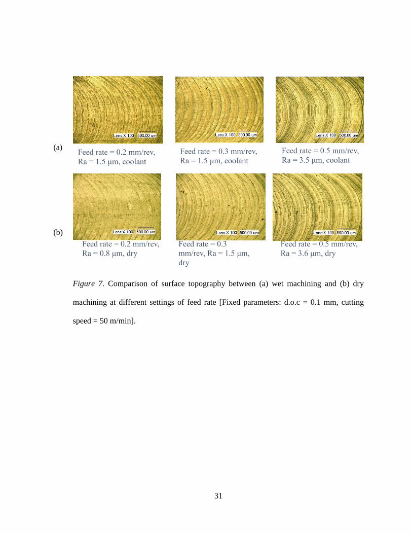
feed rate. The features of the machined surface at the different settings of feed rate are
shown in Figure 7. The tool paths are clearer at the higher settings of feed rate, which is
the main reason for the increased average surface roughness with an increasing feed rate.
The lowest average surface roughness of 0.8 μm was obtained at 0.2 mm/rev feed rate
during dry machining.
Unlike the effect of cutting speed, tool wear was found to be the same or slightly
lower in dry machining at different settings of feed rate. At 0.3 and 0.4 mm/rev, the number
of affected flutes (tool wear) was found to be lower in dry machining compared to that of
dry machining. However, the adhesion of chips on the cutting tool edges was observed
during dry machining for all feed rate settings, as can be seen in Figure 8(b). The strong
alloying tendency of the Ti-6Al-4V is the main factor responsible for this phenomenon.
Figure 8(a) shows that the cutting tool edges are free of the adhesion of chips. However,
the cutting tools suffered from chipping around the edges during wet machining.

30
Figure 6: Effect of feed rate on (a) machining time, (b) average surface roughness, and (c)
tool wear [Fixed parameters: d.o.c = 0.1 mm, cutting speed = 50 m/min].
(a)
(b)
(c)
31
(a)
(b)
Figure 7. Comparison of surface topography between (a) wet machining and (b) dry
machining at different settings of feed rate [Fixed parameters: d.o.c = 0.1 mm, cutting
speed = 50 m/min].
Feed rate = 0.2 mm/rev,
Ra = 1.5 μm, coolant
Feed rate = 0.3 mm/rev,
Ra = 1.5 μm, coolant
Feed rate = 0.5 mm/rev,
Ra = 3.5 μm, coolant
Feed rate = 0.2 mm/rev,
Ra = 0.8 μm, dry
Feed rate = 0.3
mm/rev, Ra = 1.5 μm,
dry
Feed rate = 0.5 mm/rev,
Ra = 3.6 μm, dry

32
(a)
(b)
Figure 8. Comparison of tool wear between (a) wet machining and (b) dry machining at
different settings of feed rate [Fixed parameters: d.o.c = 0.1 mm, cutting speed = 50
m/min].
Effect of depth of cut. The effect of the depth of cut on the machining time, surface
roughness, and tool wear is introduced in Figure 9. The cutting speed and the feed rate
were kept unaltered at 50 m/min and 0.3 mm/rev, while changing the significance of the
cut. It was discovered that during the processing of Ti-6Al-4V, the coolant at a higher
significance of cut affects the machining time. As Figure 9(a) shows, there are no
qualifications in machining time while machining at a lower depth of cut. The machining
time began to augment in the midst of the dry machining when such machining was done
Feed rate = 0.2 mm/rev,
coolant
Feed rate = 0.3 mm/rev,
coolant
Feed rate = 0.2 mm/rev,
dry
Feed rate = 0.3 mm/rev,
dry Feed rate = 0.5 mm/rev,
dry
Feed rate = 0.5 mm/rev,
coolant

33
at a higher cutting depth. This is because at a higher depth of cut, the cutting tool
experiences higher cutting pressure. Also, more heat is generated due to friction at a higher
depth of cut. Therefore, if the coolant is applied during machining operations, it will
minimize the heat generated at the cutting tool and tool-workpiece interface, thus reducing
the tool wear and curtailing the machining time. The average surface roughness remained
unchanged until 0.3 mm depth of cut for both dry and wet machining, after which it
increased sharply, with a rise in the depth of cut. This is due to increased digging action,
which produces a lot of heat at the tool-workpiece interface, causing more adhesion of
chips on the cutting tools and making the tool edges blunt by eroding the sharp edges.
There was no significant difference in the average surface roughness for dry and wet
machining. Figure 10 shows the comparison of the surface topography between wet and
dry machining at different settings of depth of cut.
The research revealed that for both dry and wet machining, the lowest surface
roughness of 1.3 μm was obtained at 0.3 mm depth of cut. At a very low depth of cut, that
is, 0.1 mm, the surface roughness was slightly higher than 0.3 mm. This is probably
because at a lower depth of cut, rubbing action dominates compared to the cutting, thus
leaving tool marks on the surface and making the surface rougher. The surface topography
at 0.1 mm for dry machining, as shown in Figure 10(b), provides some indication of the
tool rubbing action on the surface. Also, at a slightly higher depth of cut (i.e., 0.3 mm), the
cutting edges come in contact with the surface very well, thus providing a smooth cutting
action. This is why a depth of cut of 0.3 mm provided the lowest surface roughness.
However, the further increase of the depth of cut would increase the cutting forces and chip
load on the tool, which would make the surface rougher again.

34
Figure 9. Effect of the depth of cut on (a) machining time, (b) average surface roughness,
and (c) tool wear [Fixed parameters: Cutting speed = 50 m/min, Feed rate = 0.3 mm/rev].
(a)
(b)
(c)

35
(a)
(b)
Figure 10. Comparison of the surface topography between (a) wet machining and (b) dry
machining at different settings of depth of cut [Fixed parameters: Cutting speed = 50
m/min, Feed rate = 0.3 mm/rev].
d.o.c. = 0.2 mm, Ra =
1.4 μm, coolant
d.o.c. = 0.3 mm/rev, Ra
= 1.3 μm, coolant
d.o.c. = 0.5 mm/rev, Ra
= 2.5 μm, coolant
d.o.c. = 0.2 mm, Ra =
1.5 μm, dry
d.o.c. = 0.3 mm, Ra =
1.3 μm, dry
d.o.c. = 0.5 mm, Ra =
2.5 μm, dry

36
(b)
Figure 11. Comparison of tool wear between (a) wet machining and (b) dry machining at
different settings of depth of cut [Fixed parameters: Cutting speed = 50 m/min, Feed rate
= 0.3 mm/rev].
d.o.c. = 0.2 mm,
coolant
d.o.c. = 0.3 mm,
coolant
d.o.c. = 0.5 mm,
coolant
d.o.c. = 0.2 mm, dry d.o.c. = 0.3 mm, dry d.o.c. = 0.5 mm, dry

37
Comparison of Coated and Uncoated Tools
Effect of Feed Rate. Figure 12 shows the effect of the feed rate on the machining
time, surface roughness, and tool wear for the wet and dry machining of Ti-6Al-4V. The
feed rate was varied at 0.3, 0.5, and 0.7 mm/rev, while the cutting speed and depth cut were
unchanged at 50 m/min and 0.3 mm, respectively. It was found that the machining time
reduces as the cutting tool moves more quickly at the higher feed rate.
There was no significant contrast in the machining time for both the coated and
uncoated tools utilizing these distinctive feed rates. The average surface roughness rose by
a feed rate for both the coated and uncoated tools, as shown in Figure 6(a). The surface
roughness was found to be lower for the tools coated with TiAlN. The features of the
machined surface at different settings of feed rate are shown in Figure 13.
The tool paths are clearer at higher settings of feed rate, which is the primary reason
for the increased average surface roughness with an increasing feed rate. The lowest
average surface roughness of 0.9 μm was obtained at 0.5 mm/rev feed rate during
machining with TiAlN tools. There was no significant difference in machining with coated
tools compared to machining using uncoated tools, as shown in Figure 14.

38
Figure 12: Effect of feed rate on (a) average surface roughness, (b) tool wear, and (c)
machining time [Fixed parameters: d.o.c = 0.3 mm, cutting speed = 50 m/min].
(a)
(b)
(c)

39
(a) (b) (c)
Figure 13: Comparison of surface topography between (a) TiCN coated tools, (b) TiAlN
coated tools, and (C) uncoated tools at different settings of feed rate [Fixed parameters:
d.o.c = 0.3 mm, cutting speed = 50 m/min].
(a) (b) (c)
Figure 14: Comparison of tool wear between (a) TiCN coated tools, (b) TiAlN coated tools,
and (c) uncoated tools at different settings of feed rate [Fixed parameters: d.o.c = 0.3 mm,
cutting speed = 50 m/min].

40
Effect of Depth of Cut. The effect of the depth of cut on machining time, surface
roughness, and tool wear is introduced in Figure 15. Some results could not be shown
because the tools broke during the experiments at 0.7 mm in the depth of cut. The cutting
speed and the feed rate were kept unchanged at 50 m/min and 0.3 mm/rev respectively,
while changing the significance of the cut. As can be seen in Figure 15(a), there was no
significant change in the machining time. The machining time remained the same for all
tools used in the machining operation with 0.5 mm in the depth of cut, but was
simultaneously continuous for the machining with TiAlN coated tools only. This is because
at a higher depth of cut, the cutting tool experienced higher cutting forces on the TiAlN
coated tools.
In addition, the heat generated due to the rising friction rises at a higher depth of
cut. Therefore, the aluminum coating maximizes the strength that can resist the heat
generated at the cutting tool and tool-workpiece interface, thus reducing the tool wear and
minimizing the machining time. The average surface roughness was found to be unchanged
until 0.5 mm depth of cut for machining with both coated and uncoated tools. Subsequently,
the TiCN coated tools and the uncoated tools were broken by an increase in the depth of
cut to 0.7 mm. This is because the high resistance of the TiAlN against heat at the tool-
workpiece interface causes more adhesion of chips on the cutting tools. There was no
significant difference in the average surface roughness of the coated and uncoated tools.
Figure 16 shows the comparison of the surface topography between machining using
coated and uncoated tools at different settings of the depth of cut. The tool wear of the
coated and uncoated tools at different depth of cut is presented in Figure 17. It was found

41
that the lowest surface roughness of 1.37 μm was obtained at 0.7 mm depth of cut with the
TiAlN coated tools. Conversely, at a slightly higher depth of cut (0.7 mm), the cutting
edges come in contact with the surface very well, thus providing a smooth cutting action
by the TiAlN coated tools. This is why a depth of cut of 0.7 mm provided the lowest surface
roughness from the TiAlN coated tools.

42
(a)
(b)
(c)
Figure 15. Effect of depth of cut on (a) machining time, (b) average surface roughness,
and (c) tool wear [Fixed parameters: Cutting speed = 50 m/min, Feed rate 0.3mm/rev].

43
(a) (b) (c)
Figure 16. Comparison of surface topography between (a) TiCN coated tools, (b) TiAlN
coated tools, and (c) uncoated tools at different settings of depth of cut [Fixed parameters:
Cutting speed = 50 m/min, Feed rate = 0.3 mm/rev].

44
(a) (b) (c)
Figure 17. Comparison of tool wear between (a) TiCN coated tools, (b) TiAlN coated tools,
and (c) uncoated tools at different settings of depth of cut [Fixed parameters: Feed Rates =
0.3 mm/rev, cutting speed = 50 m/min].

45
Conclusion
This study was conducted in two parts. The first part investigated a comparative
experimental analysis of the machinability of Ti-6Al-4V for conventional flood coolant
machining and sustainable dry machining. Also, the effects of cutting speed, feed rate, and
depth of cut on machining performance was evaluated for both conditions. The second part
examined the machinability of Ti-6Al-4V using coated and uncoated tungsten carbide tools
under dry conditions. The following conclusions can be drawn from this study:
The machining time for machining the same length of slots was found to be lower
in dry machining, indicating that it is a faster process than flood coolant machining.
Also, dry machining provides comparatively smoother surface finishes with lower
average surface roughness. Thus, the answer to the research question #1 and #2 is
yes; dry machining produces a smoother surface and is faster than flood coolant
machining.
The surface roughness increases greatly with the increase of the feed rate gradually
with the increase of the depth of cut. However, it does not change significantly with
the increase of the cutting speed.
Tool wear was found to be unpredictable and the number of affected flutes
increased with increases in the depth of cut and feed rate.
The most dominant tool wear in wet machining is flank wear and chipping, whereas
crater wear, built-up edges, and chipping are dominant in dry machining. The
addition of chips was significant at a higher depth of cut in dry machining.
Comparing all the parameters, sustainable dry machining was found to provide
better performance than wet machining in machining Ti-6Al-4V.

46
The machining of the same length of slots was discovered to be faster with uncoated
tools than coated tools under the same conditions.
Dry machining, using the AlTiN coated carbide tool, provides a smoother surface
finish with lower average surface roughness. This result provides further evidence
to support research question #2; that dry machining is faster.
The surface roughness and tool wear are comparatively higher for uncoated tools
than coated tools. Thus, the answer to research question #3 is that coated tools have
less wear than uncoated tools.
Based on the detail experimental investigations, the optimal parameters setting for
machining Ti-6Al-4V were identified. Considering all those factors, a cutting speed
of 50 m/min, feed rate of 0.3 mm/rev, and depth of cut of 0.3 mm were found to
provide improved performance at both dry and wet machining of Ti-6Al-4V.
Future Research
Future research could focus on the cutting force analysis during the dry machining
of Ti-6Al-4V using coated and uncoated carbide tools. It can be hypothesized from the
results of this research that there may be reduction of cutting forces during the machining
of Ti-6Al-4V with TiAlN coated tools that resulted in the reduced tool wear and improved
surface finish at higher settings of cutting speed, feed rate and depth of cut. The application
of green/environmental friendly cutting fluid and minimum quantity lubrication (MQL)
will be considered in the future research.

47
References
Barbosa, G. A. S., Bernardes, S. R., de França, D. G. B., das Neves, F. D., de Mattos, M.
D. G. C., & Ribeiro, R. F. (2014). Correlation between vertical misfits and stresses
over implants from castable frameworks made of different alloys. Journal of
Craniofacial Surgery, 25(6), 2062–2065.
Bouzakis K. D., Gerardis S., Katirtzoglou G., Makrimallakis S., Bouzakis A., Cremer R.,
Fuss H. G., Application in Milling of Coated Tools with Rounded Cutting Edges
after Film Deposition, CIRP Annals – Manufacturing Technology, 58(1) (2009):
61–64
Corduan, N., Himbert, T., Poulachon, G., Dessoly, M., Lambertin, M., Vigneau, J., Payoux,
B.,Wear Mechanisms of New Tool Materials for Ti6Al4V High Performance
Machining, CIRP Annals - Manufacturing Technology, 52(1) (2003): 73–76
De Bruyn, R. (2014). Improving and implementing advanced milling techniques for the
manufacture of selected titanium aerospace parts (Doctoral dissertation,
Stellenbosch University).
Ezugwu, E., & Wang, Z. (1997). Titanium alloys and their machinability—a review.
Journal of Materials Processing Technology, 68(3), 262-274.
Ezugwu, E.O., Bonney, J., Da Silva, R.B., Machado A.R., & Ugwoha, E. (2009). High
productivity rough turning of Ti-6Al-4V alloy, with flood and high-pressure
cooling. Society of Tribologists and Lubrication Engineers, Tribology
Transactions, 52(3), 395–400. doi:10.1080/10402000802687866
Fanning, J. (2013). U.S. Patent No. 8,454,768. Washington, DC: U.S. Patent and
Trademark Office.

48
Hao, X., Pei, S., Wang, L., Xua, H., He, N., & Lu, B. (2014). Microtexture fabrication on
cylindrical metallic surfaces and its application to a rotor-bearing system. The
International Journal of Advanced Manufacturing Technology, 78, 1–9.
He, J., Ding, W. F., Miao, Q., Zhao, B., Liu, Z. W., & Liang, Y. M. (2013). Experimental
investigation on surface topography for PTMCs during high speed grinding.
Applied Mechanics and Materials, 423, 699–703.
Hosseini, A., & Kishawy, H. A. (2014). Cutting tool materials and tool wear. In Machining
of titanium alloys (pp. 31–56). Berlin, Heidelberg: Springer.
Jin, D., & Liu, Z. (2012). Effect of cutting speed on surface integrity and chip morphology
in high-speed machining of PM nickel-based superalloy FGH95. The International
Journal of Advanced Manufacturing Technology, 60(9-12), 893–899.
Kaynak, Y. (2014). Machining and phase transformation response of room-temperature
austenitic NiTi shape memory alloy. Journal of Materials Engineering and
Performance, 23(9), 3354–3360.
Mahmud, N., Yahya, A., Rafiq, M., Samion, S., & Safura, N. L. (2012, February).
Electrical discharge machining pulse power generator to machine micropits of hip
implant. In 2012 International Conference on Biomedical Engineering (ICoBE)
(pp. 493–497). IEEE.
Nandy, A. K., Gowrishankar, M. C., & Paul, S. (2009). Some Studies on high-pressure
cooling in turning of Ti-6Al-4V. International Journal of Machine Tools &
Manufacture, 49(2), 182–198. doi:10.1016/j. ijmachtools.2008.08.008
Neuss, S., Panfil, C., Duarte Campos, D. F., Weber, M., Otten, C., Reisgen, U., & Fischer,
H. (2015). Adhesion of human mesenchymal stem cells can be controlled by

49
electron beam-microstructured titanium alloy surfaces during osteogenic
differentiation. Biomedical Engineering, 60(3), 215–223.
Olvera, D., de Lacalle, L. N. L., Urbikain, G., Lamikiz, A., Rodal, P., & Zamakona, I.
(2012). Hole making using ball helical milling on titanium alloys. Machining
Science and Technology, 16(2), 173–188.
Palanisamy, S., McDonald, S. D., & Dargusch, M. S. (2009). Effects of coolant pressure
on chip formation while turning Ti6Al4V alloy. International Journal of Machine
Tools & Manufacture, 49(9), 739–743. doi:10.1016/j.ijmachtools.2009.02.010
Roccella, S., Cacciotti, E., Candura, D., Mancini, A., Pizzuto, A., Reale, A., Tati, A., &
Visca, E. (2013). Ultrasonic test of carbon composite/copper joints in the ITER
divertor. Fusion Engineering and Design, 88(9), 1802–1807.
Scintilla, L. D., & Tricarico, L. (2013). Fusion cutting of aluminum, magnesium, and
titanium alloys using high-power fiber laser. Optical Engineering, 52(7), 1–7.
Venkata, R. R., & Kalyankar, V. D. (2012). Parameter optimization of modern machining
processes using teaching–learning-based optimization algorithm. Engineering
Applications of Artificial Intelligence, 26(1), 524–531. doi:10.1016/j.
engappai.2012.06.007
Wyen, C. F., Jaeger, D., & Wegener, K. (2013). Influence of cutting edge radius on surface
integrity and burr formation in milling titanium. The International Journal of
Advanced Manufacturing Technology, 67(1-4), 589–599.