a study on pcs characteristics using modeling of solar cell
TRANSCRIPT
International Journal of Computing and Digital Systems ISSN (2210-142X)
Int. J. Com. Dig. Sys. 9, No.3 (May-2020)
E-mail: [email protected], [email protected]
http://journals.uob.edu.bh
A Study on PCS Characteristics Using Modeling
of Solar Cell
Hyun-Sook Lee1and Moon-Taek Cho2
1 Department of Technology Entrepreneurship, Dongguk University, Seoul
2 Department of Electrical & Electronics Engineering, Daewon University College, Chungbuk Province
Received 26 Nov. 2019, Revised 4 Mar. 2020, Accepted 13 Apr. 2020, Published 1 May 2020
Abstract: In this paper, we modeled the devices used in PV system for easy analysis. The modeled library was used to simulate the
effects of solar cell temperature and spatial radiation. In addition, the operation of the DC-DC buck-boost converter and the MPPT
control system was modeled and simulated for complete operation of the PV system. In addition, to prove the operation of the
simulation, the experiment was performed by configuring the actual system under the same conditions as in the simulation, and it was
confirmed that the results of the experiment and the simulation result performed the same operation. In addition, we proposed a single-
phase 3kW grid-connected solar power converter and confirmed the possibility of great help in improving efficiency and power factor.
In the future, it can be used as a stand-alone system when attaching ESS by using solar inverter, and it is possible to regenerate energy
to the battery power side, and it has efficiency of more than 95 [%] and has an energy saving effect.
Keywords: PV system, Buck-boost converter, MPPT, Power factor, ESS, Battery
INTRODUCTION
The photovoltaic device is composed of a solar cell, a power converter, a connection panel, a support structure, and the like. The most important of these is solar cells, and power converters play an important role as well. Power converters are in charge of converting direct current electricity produced from solar cells into alternating current electricity that can be used at home. In addition, the junction board for supplying direct current electricity produced by several solar cells to the power converter also plays an important role.
In the field of power electronics such as converters, inverters, and choppers composed of power semiconductors, various semiconductor power converters with excellent characteristics began to be developed and distributed with the development of thyristors. In addition, due to the development of power semiconductor technology, new devices such as IGBT and new devices have been developed and used in various power conversion devices, and the introduction of microprocessor enables control technology that was impossible in the past to realize power conversion technology and control. The method is also evolving greatly.
According to the recent trend of the power converter market, it is impossible to conduct sales activities in the market unless SMEs have secured cost-saving technology in a situation where low prices are constantly being demanded. The companies that install solar systems are having difficulty in supplying and receiving power converters. Since the development form of grid-connected solar power converter has been transformed into a large capacity, it is difficult to research and develop various technologies, and it is difficult to establish a technology for realizing a converter efficiency of more than 97 [%] using the unit power factor control method.
In this paper, in consideration of these problems, we
propose a system that can operate stably even when the
voltage fluctuation rate is severe or unbalanced power,
and can control with high efficiency and unit power factor.
Integrating the converter and the connection panel
reduces cost and improves efficiency.
MODELING OF THE PROPOSED PV CELL
In this In practical solar cells, resistive losses are tied to a series resistor R_s. This effect is very visible in PV modules configured in series, and the value of the resistor increases with the number of cells.
http://dx.doi.org/10.12785/ijcds/090313

496 Hyun-Sook Lee & Moon-Taek Cho: A Study on PCS Characteristics Using Modeling of Solar Cell
http://journals.uob.edu.bh
Figure 1. PV Cell Model.
To summarize these effects, the voltage-current relationship of PV cells can be written as in equation (1).
𝐼 = 𝐼𝑠𝑐 − 𝐼01 [𝑒𝑞(
𝑉+𝐼𝑅𝑠𝑘𝑇
) − 1] − 𝐼02 [𝑒𝑞(
𝑉+𝐼𝑅𝑠2𝑘𝑇
) − 1] − (𝑉+𝑅𝑠
𝑅𝑝) (1)
The combination of the diodes 𝐷1 and 𝐷2 allows
Equation (1) to be represented as equation (2).
𝐼 = 𝐼𝑠𝑐 − 𝐼0 [𝑒𝑞(
𝑉+𝐼𝑅𝑠𝑛𝑘𝑇
) − 1] − (𝑉+𝑅𝑠
𝑅𝑝) (2)
It can be seen that the series resistance 𝑅𝑠 gives
most of the electrical parameters of the solar cell by the
fill factor.
If the analysis is limited by the effect of series
resistance alone, the solar cell is modeled as a diffusion
diode and can be summarized as in equation (3).
𝐼 = 𝐼𝐿 − 𝐼0 [𝑒𝑞(
𝑉+𝐼𝑅𝑠𝑛𝑘𝑇
) − 1] (3)
In open circuit, it can be written as equation (4).
0 = 𝐼𝐿 − 𝐼0 [𝑒𝑞(
𝑉𝑜𝑐𝑛𝑉𝑇
)− 1] (4)
From equation (2-14), 𝐼𝑜 becomes like equation
(5).
𝐼0 =𝐼𝐿
(𝑒
𝑉𝑜𝑐𝑛𝑉𝑇)
= 𝐼𝐿𝑒−𝑉𝑜𝑐𝑛𝑉𝑇 (5)
Substituting equation (5) into equation (3) yields
equation (6).
𝐼 = 𝐼𝐿 − 𝐼𝐿𝑒−𝑉𝑜𝑐𝑛𝑉𝑇 (𝑒
𝑉+𝐼𝑅𝑠𝑛𝑉𝑇 − 1) = 𝐼𝐿 (1 − 𝑒
𝑉+𝐼𝑅𝑠−𝑉𝑜𝑐𝑛𝑉𝑇 ) (6)
At maximum power point, we can write as in
equation (7).
𝐼𝑚 = 𝐼𝐿 (1 − 𝑒𝑉𝑚+𝐼𝑅𝑠−𝑉𝑜𝑐
𝑛𝑉𝑇 ) (7)
If equation (7) is multiplied by voltage V and the
derivative is equal to 0, the maximum power point
coordinate can be expressed as equation (8).
𝐼𝑚 + (𝐼𝑚 − 𝐼𝐿) (𝑉𝑚−𝐼𝑚𝑅𝑠
𝑛𝑉𝑇) = 0 (8)
Knowing 𝑉𝑜𝑐 and 𝐼𝐿 , 𝑉𝑚 and 𝐼𝑚 can be
calculated from equations (7) and (8).
The maximum power derived from the solar cell
can be calculated by equation (9).
𝑃′𝑚 = 𝑃𝑚 − 𝐼𝑚2 𝑅𝑠 (9)
Equation (9) means that the maximum power point
is moved to the same place as the current value 𝐼𝑚.
In Eq. (9), multiplying by and dividing by the
second term on the right gives us the equation (20).
𝑃′𝑚 = 𝑃𝑚 (1 −𝐼𝑚
𝑉𝑚𝑅𝑠) (10)
Assuming that Eq. (11) is obtained, Eq. (12) can be
obtained.
𝐼𝑚
𝑉𝑚=
𝐼𝑠𝑐
𝑉𝑜𝑐 (11)
𝑃′𝑚 = 𝑃𝑚 (1 −𝐼𝑠𝑐
𝑉𝑜𝑐𝑅𝑠) = 𝑃𝑚(1 − 𝑟𝑠) (12)
Fill Factor can be calculated | required from
equation (12) like equation (13).
𝑃𝐹 =𝑃𝑚′
𝑉𝑜𝑐𝐼𝑠𝑐=
𝑃𝑚(1−𝑟𝑠)
𝑉𝑜𝑐𝐼𝑠𝑐= 𝐹𝐹0(1 − 𝑟𝑠) (13)
Figure 2 shows the V-I curve of the PV cell
according to the series resistance 𝑅𝑠 under the
condition of 1000[W/𝑚2] solar radiation.
Figure 2. V-I curve of PV cell.
This is the loss associated with the micro-leakage
current flowing through the resistor in paralleled

Int. J. Com. Dig. Sys. 9, No.3, 495-501 (May-2020) 497
http://journals.uob.edu.bh
devices. This is represented by shunt resistor 𝑅𝑝. This
effect is less pronounced in PV modules configured in
series, and is significant when large numbers of PV
modules are connected in parallel.
Figure 3. V-I curve of PV cell (Irradiation 1000[W/𝑚2])
Shunt resistance degrades the operation of solar
cells. To eliminate this effect, set the series resistor and
the second diode to set 𝑅𝑠 = 1 × 10⁻⁶[𝛺], 𝐽02 = 0 .
Figure 3 shows the resulting waveform at this time. The
open circuit voltage is very slightly modified unless the
shunt resistance is at a small value. If 𝑅𝑠 = 0, 𝐽02 = 0,
V = 0 becomes equation (14).
𝐼𝑠𝑐 = 𝐼𝐿 (14)
To eliminate the effect of the recombination diode
in Figure 4, select the high shunt resistance and the low
series resistance.
Figure 4 shows the simulation result when the
value of parameter 𝐽02 is changed. This shows the
effect of the recombination diode, which is much less
characteristic at the open circuit voltage and FF. The
short circuit current is constant.
Figure 4. V-I curve at J_02 change of recombination diode.
POWER CONVERTER DESIGN CONNECTED WITH
SOLAR CELL
When applied as a voltage-type power converter using PWM (Pulse Width Modulation), reactive power can be adjusted, enabling high power factor operation. In addition, in the case of controlling a rotating device, there is a characteristic that the voltage and phase of the AC side can be changed, which has the advantage of simplifying the structure of the power converter.
As shown in Fig. 5, the voltage converter has a structure in which a 180^o energized power converter and an AC power source are reacted together. The power converter is a voltage converter using a forced current structure or a device having self-extinguishing capability.
Since the magnitude of the DC voltage is not defined, the function of controlling the DC voltage must be provided as shown in Fig. 5. In addition, since the AC power factor is not defined, reactive power can be generated and reactive power can be controlled.
Figure 5. Construction and production of proposed power converter.
SIMULATION RESULTS AND DISCUSSION
MPPT control in DC-DC step-down chopper: In order to prove the validity of the modeling and simulation using PSPICE, the same system was actually manufactured and tested. A block diagram of the overall configuration of the experimental setup is shown in Figure 6. A DC-DC buck-boost converter with the same value as in the simulation was fabricated for output voltage adjustment, and the controller used for overall system control was implemented in C-language using TMS chip. The controller consists mainly of an A / D converter for voltage and current detection, an MPPT algorithm implementer for maximum output point control, and a PWM signal generator for generating control signals of the converter.

498 Hyun-Sook Lee & Moon-Taek Cho: A Study on PCS Characteristics Using Modeling of Solar Cell
http://journals.uob.edu.bh
Figure 6. Block diagram of main system.
The MPPT algorithm uses the improved P & O MPPT, and Figure 7 shows the actual controller.
Figure 7. Real controller.
(a) Output Without MPPT.
(b) Output when MPPT is added
Figure 8. Wave of PV system.
Figure 8 shows the output waveform displayed by driving the actual controller. The output of the PV system is an oscilloscope waveform implemented on a PC using labview for processing and storing various data. As shown in the figure, a good experimental result showing the normal maximum output was obtained after the transient time of about 50ms. This confirms that the previous simulation was performed correctly. Therefore, the simulation using the PSPICE library proposed in this paper can be used for new system development and performance evaluation as well as to improve the reliability.
Solar power converter test device and experiment: order to test the basic performance characteristics of the single-phase 3kW low voltage inverter developed for solar power generation and to derive the improvement in performance, the test apparatus is constructed as shown in the following Figure 8. It is a 10kVA three-phase voltage-type PWM converter with a 600V / 150A IGBT module rating, 1mH inductance, and 3000μF filter capacitor. The sample and hold circuit was composed by using analog input multiplexer by detecting the three-phase supply voltage and the supply current, respectively. Figure 9 shows the test setup for the performance test of the power converter.
Figure 9. Configuration of electric power converter test equipment.
Int. J. Com. Dig. Sys. 9, No.3, 495-501 (May-2020) 499
http://journals.uob.edu.bh
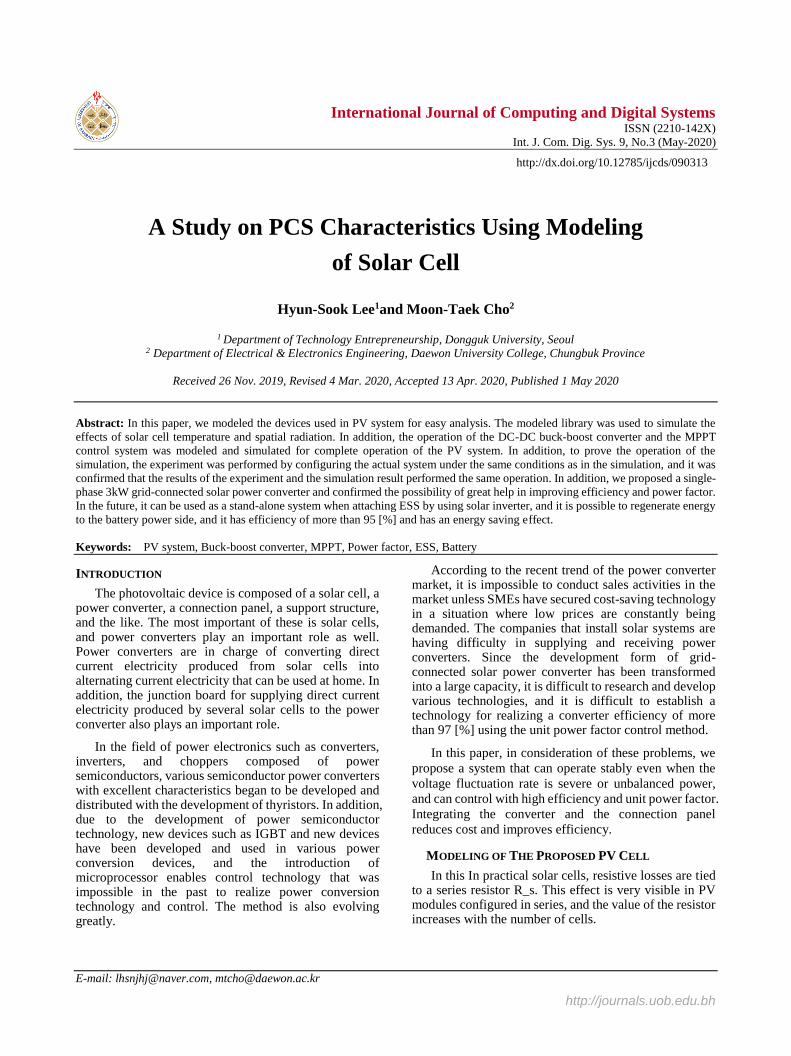
Figure 9. Test equipment used for electric power converter test.
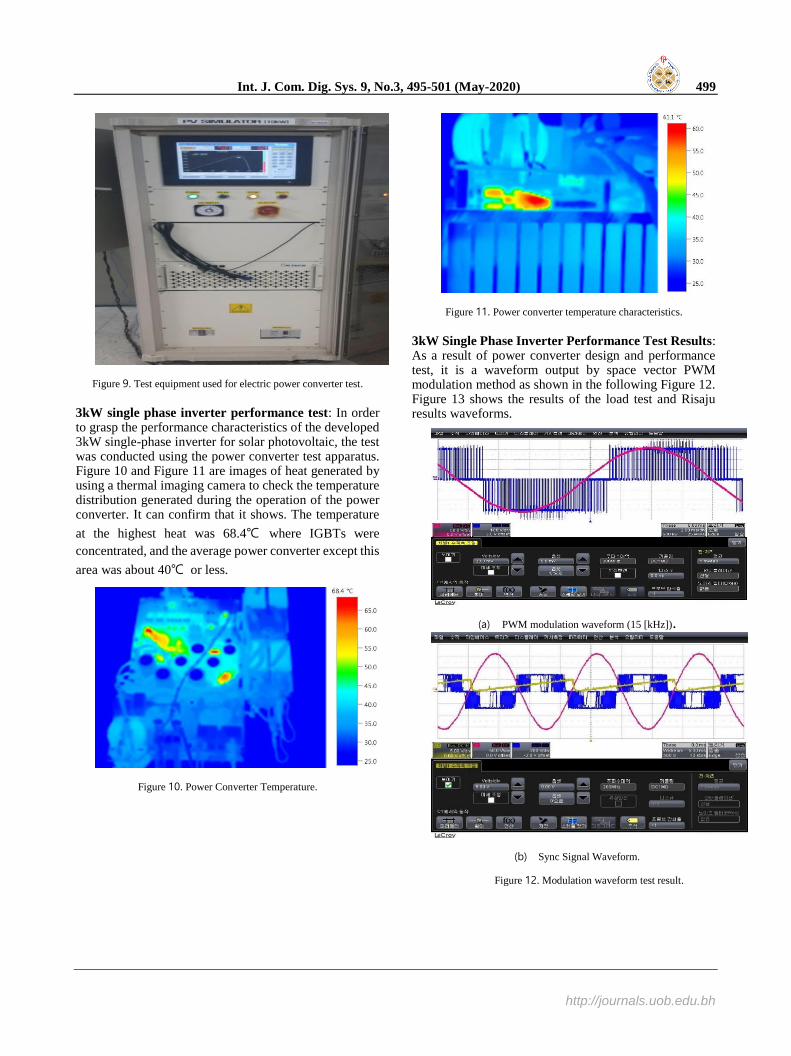
3kW single phase inverter performance test: In order to grasp the performance characteristics of the developed 3kW single-phase inverter for solar photovoltaic, the test was conducted using the power converter test apparatus. Figure 10 and Figure 11 are images of heat generated by using a thermal imaging camera to check the temperature distribution generated during the operation of the power converter. It can confirm that it shows. The temperature
at the highest heat was 68.4℃ where IGBTs were
concentrated, and the average power converter except this
area was about 40℃ or less.
Figure 10. Power Converter Temperature.
Figure 11. Power converter temperature characteristics.
3kW Single Phase Inverter Performance Test Results: As a result of power converter design and performance test, it is a waveform output by space vector PWM modulation method as shown in the following Figure 12. Figure 13 shows the results of the load test and Risaju results waveforms.
(a) PWM modulation waveform (15 [kHz]).
(b) Sync Signal Waveform.
Figure 12. Modulation waveform test result.

500 Hyun-Sook Lee & Moon-Taek Cho: A Study on PCS Characteristics Using Modeling of Solar Cell
http://journals.uob.edu.bh
(a) Load test.
(b) Risaju waveform.
Figure 13. Load test and Risaju result waveform.
CONCLUSIONS
In this paper, we modeled the simulation so that it can be easily performed before the actual PV system is manufactured. The simulation tool uses PSPICE, which enables intuitive electrical circuit simulation. The modeled library was also used to simulate the effects of temperature and spatial radiation on solar cells. In addition, the complete operation system for the DC-DC buck-boost converter and the maximum power point tracking (MPPT) control system was modeled and simulated to ensure good operation of the PV system. Also, in order to prove the operation of the simulation, the experiment was carried out by constructing a real system with the same conditions in the simulation. Considering capacity, we have secured design data that can be diversified and large in capacity. In particular, GaN type MOSFET is a next-generation switching device, and it is confirmed that it is not inferior, and it is possible to extend the switching frequency to 200kHz and greatly improve the efficiency and power factor by greatly reducing the size of the heat sink. It was confirmed.
Therefore, the modeling performed in this paper was confirmed to be accurate, and it can be used to facilitate the simulation of the basic photovoltaic power generation system.
REFERENCES
[1] Y.Yusof, S,Sayuti, M.Latif, and M.Wanik, 2004. Modeling and Simulation of maximum power traker for photovoltaic system. in Proceedings of Power and Energy Conference, Nov., pp.88-93
[2] Kyritsis, A.Ch., Tatakis, E.C., Papanikolaou, N.P., 2008 “Optimum Design of the Current-Source Flyback Inverter for Decentralized Grid-Connected Photovoltaic Systems”, Energy Conversion, IEEE Transactions on Volume 23, pp.281–293.
[3] M.H.Rashid, 2004,Power Electronics Circuits:Devices and Applications, 3rd edition, Upper Saddle River, NJ: Prentice-Hall.
[4] Sahlstrom, Theodore D., Hausgen, Paul E., Guerrero, Jim, Howard, Alex D., Snyder, Neil A., 2008. Ultraviolet degradation testing of space protective coatings for photovoltaic cells, Photovoltaic Specialists Conference, 2008. PVSC '08. 33rd IEEE, pp.1-5.
[5] D.W.Hart,2008.Introduction to Power Electronics, Upper Sadlle River, NJ:Prentice-Hall, 1997 [7] Fangrui Liu, Shanxu Duan, Fei Liu, Bangyin Liu, Yong Kang, "A Variable Step Size INC MPPT Method for PV Systems", Industrial Electronics, IEEE Transactions on Volume 55, pp.2622–2628.
[6] Xuecheng Zou, Kai Yu, Zheng, Xiaofei Chen, Zhige Zou, Dingbin Liao, 2008.Dynamic Current Limitation Circuit for White LED Driver.IEEE, PP.898-901.
[7] Van der Broeck, Heinz; Sauerlander, Georg; Wendt, Matthias.2007.Power Driver Topologies and control schemes for leds.IEEE, PP.1319-1325.
[8] Wing Yan Leung, Tsz Yin Man; Mansun Chan, 2008.A high-power –LED driver with power-efficient LED-current sensing circuit” IEEE, PP.354-357.
[9] Huang-Jen Chiu, Yu-Kang Lo, Jun-Ting Chen, Shih-Jen Cheng, Chung-Yi Lin, Shann-Chyi Mou, 2010. A High-Efficiency Dimmable LED Driver for Low-Power Lightng Applications. IEEE, PP.735~743, 2010.
[10] Tzuen-Lih Chern, Li-Hsiang Liu, Ping-Lung Pan, Yi-Jie Lee, Single-stage Flyback converter for constaant current output LED driver with power factor correction. IEEE, PP.2891-2896.
[11] Yoo Juhyun, Kim Kookjin, Jeong Yeongho.2007. Electial Properties of Low Temperature Sintering Step-Down Multilaye Piezoelectric Transformer” JJAP Vol 46, Issue 20, pp.486-488.
[12] Soon-Jong Jeong, 2008. Two-layered Piezoelectric bender device for micro-power generator. ScienceDirect, Vol 148, Issuel, 4November, pp.158-167.
[13] Hyun-Cheol Song, Multilayer piezoelectric energy scavenger for Large current generation. SpringerLink, Vol 23, Num 2-4, pp.301-304.
[14] Suan Dwari, Leila Parsa.2008. Efficient low voltage direct AC/DC converters for self-powered wireless sensor nodes and mobile electronics. IEEE Telecommunications Energy Conference. 1-7.
[15] M. J. Guan, W. H. Liao. 2007. On the efficiencies of piezoelectric energy harvesting circuits towards storage device voltages. IOP Smart Mater. Struct, Vol. 16, No. 2, pp. 498-505
[16] Shar. Roundy. 2003. Energy Scavenging for Wireless Sensor Nodes with a Focus on Vibration to Electricity Conversion”, Ph.D. Dissertation, U.c. Berkeley.
[17] J. A. Paradiso and T. Strner. 2005. Energy Scavenging for Movile and Wireless Electronics. IEEE Pervasive Computing, 4:18-27.
[18] G. K. Ottman, H. F. Hoffman, A. C. Bhatt and G. A. Lesieutre, 2003. Adaptive Piezoelectric Energy Harvesting Circuit for Wireless Remote Power Supply. IEEE Trans. Power Electron, 18:696-703.

Int. J. Com. Dig. Sys. 9, No.3, 495-501 (May-2020) 501
http://journals.uob.edu.bh
[19] M. Philipose, J. R. Smith, B. Jiang, A. Mamishev, S. Roy and K. Sundara-Rajan. 2005. Battery-Free Wireless Identification and Sensing. IEEE Pervasive Computing, 4:37-45.
FIGURE CAPTIONS
Fig. 1. PV Cell Model. Fig. 2. V-I curve of PV cell.
Fig. 3. V-I curve of PV cell (Irradiation 1000[W/𝑚2])
Fig. 4. V-I curve at J_02 change of recombination diode.
Fig. 5. Construction and production of proposed power converter. Fig. 6. Block diagram of main system.
Fig. 7. Real controller.
Fig. 8. Wave of PV system. Fig. 9. Configuration of electric power converter test equipment.
Fig. 9. Test equipment used for electric power converter test.
Fig. 10. Power Converter Temperature. Fig. 11. Power converter temperature characteristics.
Fig. 12. Modulation waveform test result.
Fig. 13. Load test and Risaju result waveform.
Hyun-Sook Lee Department of
Technology Entrepreneurship, Dongguk
University, Seoul … … … She was born
in Korea on May 06, 1969. She received
the B.S., M.Edu. degrees from Kyunghee
University Korea in 2017.. Currently, she
is a manager in the Mokwon University,
Korea.
Moon-Taek Cho Department of
Electrical & Electronics Engineering,
Daewon University College,
Chungbuk Province
He was born in Korea on February
23, 1965. He received the B.S.,
M.Eng. and Ph.D. degrees from
Myongji Univ. Korea in 1988, 1990
and 1999, respectively. Currently, he
is a professor in the Daewon Univ.
College, Korea. His special field of interest includes power
electric, electrical machine, new renewable energy, super-
capacitor, PSPICE, CASPOC.