a study of means to prevent rotational falls within … rotational falls within cross country ... a...
TRANSCRIPT

A Study of Means to Prevent Rotational Falls
within Cross Country Eventing
2009-09-23 Anders Flogård
MIM Construction AB

2
Abstract Within Cross Country Eventing a number of forward rotational falls are registered every year. Sometimes the horse as well as the rider sustains severe injuries. Frangible and deformable structures have been suggested to make the Cross Country fences less aggressive. Some field tests have been performed earlier but no data showing the potential of such a frangible system has been presented. This study tries to verify the potential of such a system. Three different test fences were built and tested with force limiting devices. Forces were physically simulated and measured during impact with the fences. A real world case was recorded with a high speed video at a Cross Country Event. Test results show a great potential to limit the risk of sustaining severe injuries in Cross Country Eventing. Most important is to reduce the impulse given to the horse and to control the fall motion of the fence when the force limiting device is triggered.

3
Index A Study of Means to Prevent Rotational Falls within Cross Country Eventing ........................ 1Abstract ...................................................................................................................................... 21. Introduction ........................................................................................................................ 4
1.1 Background .................................................................................................................. 41.2 Objectives .................................................................................................................... 4
2. Methods and materials ....................................................................................................... 52.1 Mechanical Testing ...................................................................................................... 52.1.1 Hinges ...................................................................................................................... 52.1.2 Fences ...................................................................................................................... 52.1.3 Force limiters ........................................................................................................... 62.1.4 Simulating the horse ................................................................................................ 62.1.5 Data Acquisition ...................................................................................................... 72.2 Practical Testing .......................................................................................................... 8
3 Results ................................................................................................................................ 93.1 Mechanical Testing ...................................................................................................... 93.2 Practical Testing ........................................................................................................ 11
4 Discussion ........................................................................................................................ 125 Recommendations ............................................................................................................ 13

4
1. Introduction
1.1 Background Within Cross Country Eventing all fences are traditionally considered stationary. This leads to a number of forward rotational falls every year. Some of them have severe consequences as the fall is uncontrolled and the horse often falls on its head and neck. Different studies have shown that the risk of the rider is less than the risk of the horse during the fall. Still, a number of riders are seriously injured or killed every year. Suggestions have been made to change the structure of the Cross Country fences to make them frangible and let them collapse. Some systems have been field tested but no statistical results have been presented up to date. The owner of MIM Construction AB, Mr. Mats Björnetun, has a history as an Event Director. As safety is one of the prime parameters as an Event Director it is only natural that he started to think about how to prevent rotational falls with frangible fences. After looking at what others had been doing he developed a couple of ideas and presented them as a project to one of his employees, the author of this report, Mr. Anders Flogård. Mr. Flogård has a history as a research engineer at the University of Chalmers within the field of vehicle safety. With experience from biomechanical testing, injury prevention and crash reconstructions he brought some more knowledge about the dynamic aspects and testing into the project. MIM Construction AB is a company that traditionally develops and produces car accessories. One of the main products are crash tested cargo separator safety nets. MIM Construction has the experience of producing crash zones that controls the loads in mechanical safety systems.
1.2 Objectives The objective of this study is to verify the potential of a structured solution that lets Cross Country Event fences collapse in a controlled way when the risk of a rotational fall is present.

5
2. Methods and materials Two different tests were made to study the potential of frangible Cross Country Eventing fences. One was a mechanical test and one was a practical test at a Cross Country Event.
2.1 Mechanical Testing
2.1.1 Hinges If hinges is used in a fence construction part of the fence weight is carried by the hinges. This makes the fence less heavy in a restoration situation and the exact position of the fence is repeatable. If placed low behind the post they make the fence move forwards and down to the ground if hit by an attempting horse (Figure 1). This is most likely the fastest way to move the fence out of the way as the forward speed of the fence is transferred into a speed towards the ground. It keeps the fence from traveling along with the horse disturbing it when trying to find the ground again with its feet to restore balance. Hinges can be combined to make different fence types collapsible (Figure 2). Two different types of hinges were produced to facilitate the different fence constructions used in this study.
Figure 1. Collapsible Gate Fence with hinges placed low behind the post.
2.1.2 Fences Three different test fences were built to test the force limiting devices. The first was a Gate fence, the second was a Table fence and the last a Post & Pole fence. The Gate fence was provided with hinges in the ground level making it fall flat to the ground if hit. The Table Fence was made like a parallelogram with hinges and was stopped approximately half way to the ground. The Post & Pole fence was made with hinges less than half the way to the ground.
6
Figure 2. Collapsible Table Fence.
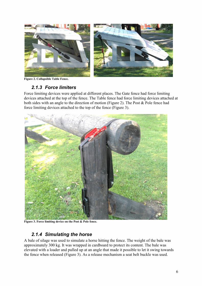
2.1.3 Force limiters Force limiting devices were applied at different places. The Gate fence had force limiting devices attached at the top of the fence. The Table fence had force limiting devices attached at both sides with an angle to the direction of motion (Figure 2). The Post & Pole fence had force limiting devices attached to the top of the fence (Figure 3).
Figure 3. Force limiting device on the Post & Pole fence.
2.1.4 Simulating the horse A bale of silage was used to simulate a horse hitting the fence. The weight of the bale was approximately 300 kg. It was wrapped in cardboard to protect its content. The bale was elevated with a loader and pulled up at an angle that made it possible to let it swing towards the fence when released (Figure 3). As a release mechanism a seat belt buckle was used.

7
Figure 4. The bale simulating the incoming horse.
2.1.5 Data Acquisition A Brick data acquisition system was used to collect the data from the two Interface 5000 lbs force transducers. The data was collected at 12800 Hz and a 2950 Hz Anti Aliasing filter was used. A total of 4 seconds of data was measured with 0.5 seconds of pre-trig data. An attachment was made for each fence to hold the two force transducers in place. A steel bar was placed in front of the force transducers. This made it possible to hit the fence and measure the forces necessary to move it away (Figure 2).

8
Figure 5. Force transducers (blue) mounted on the Post & Pole fence. A Casio Exilim EX-FH20 was used to collect a high speed video recording with a picture frequency of 420 Hz. The video was also used to estimate the speed of the bale.
2.2 Practical Testing Three collapsible fences was tested at a CNC*** Cross Country Event. The first was a Post & Pole fence, the second a Gate fence and the third a Table fence. Only one was subjected to mistakes during the jump attempt by the horses; the Gate fence. The Gate fence was difficult due to being placed partly in shadow with sun just before it and a row of flowers in front of it. The fence was filmed with a Casio Exilim EX-FH20 with a picture frequency of 420 Hz. The force limiting devises where exchanged whenever necessary during the event.

9
3 Results
3.1 Mechanical Testing The fences made with hinges and force limiting devices worked as expected with no other damages during the test except than the breakable device limiting the force. The force level of the Gate fence was measured in three different tests with and without the force limiting device. The speed of the test bale was approximately 4.5 m/s. During the test the maximum force levels differed from 8.9 kN to 20 kN. With the force limiting device a force of maximum 9.3 kN was needed to push the Gate fence away. A plastic tape was used to retain the gate in the first test with the force limiting device removed. The difference was small; without the force limiter the force level was 8.9 compared to 9.3 kN with the force limited version. The time duration was approximately the same. The contribution of the force limiter to the total force was very small compared to not strapping the fence. In the test with a firm attachment of the pole to the post the force level was more than doubled. The force level rose to 20 kN. Even more interesting was the time duration which was four times longer. The impulse anticipated to slow down the bale was 262 Ns with the force limiting device compared to 2445 Ns in the rigid case. The impulse rose by more than 9 times. This reduction in impulse with a force limiting device is in direct comparison to the reduction in rotational speed of the horse.
Figure 6. Gate fence force levels. A rigid fence compared to two different fences that move out of the way.

10
The force level of the Table fence was higher with the higher weight of the fence that had to be moved away. Maximum force was 13.7 kN. The test speed of the bale was 3.9 m/s. The impulse needed was 471 Ns which is still significantly lower than the rigid 2445 Ns. The force level of the Post & Pole fence was close to the level of the Table fence. The test speed of the bale was higher, 4.8 m/s. Maximum force level was 13.4 kN. The impulse was 536 Ns. A second test with the Post & Pole fence was made with a more upwards hit angle. This angle was supposed to simulate a horse trying to jump over at a too close position thus lifting the fence at the same time as pushing forwards. With a bale test speed of 4.4 m/s the force level was 12.6 kN. The impulse was 536 Ns. The difference compared to a horizontal hit is small and is believed to mostly depend on the speed difference of the bale due to its radial swing motion.
Figure 7. Force levels of each test as a function of time.

11
3.2 Practical Testing Several horses misjudged the CNC*** Gate fence and hit it hard. None of them fell or had any other problems after passing the fence. One horse got trapped with one knee below the top edge (Figure 8). The horse started rotating forward but didn’t have any problem to regain control as the fence moved out of the way and the horse got its feet back on the ground.
Figure 8. Snapshot from high speed video. Right knee is caught by the fence. The test shows that the risk of a rotational fall was reduced in this case.
Figure 9. Snapshot from high speed video. A horse hitting the fence breaking the force limiting device.

12
4 Discussion An implemented solution that improves the chances in a rotational fall will make a dramatic change in number of severe injuries. Such a solution must not change the spirit of Eventing; a tremendous test of horsemanship with a certain risk factor making the difference between competitors. Thus, changing the general design of cross country fences will not be a solution. A solution must reflect on the traditions of Eventing and work with a number of different fence designs. The best solution takes into account all benefits that are possible together with traditional fence design. Eventing must remain a fair sport; a solution must be repeatable, reproducible and simple. A solution must be systematic with a certain level of control to assure a fair sport. The time to restore a fence is critical if there are spectators. It is also of importance that they can be restored without a specially trained expert A comparison test between the force limited fence and a rigid fence shows that the impulse given to the horse will be significantly lower with a force limiter. The magnitude of the impulse is a direct comparison to the rotational speed the horse exhibits after hitting the fence. In low speed jumps with light weight fences like the Gate fence the rotational speed of the horse can thus be reduced to less than a tenth of what is normal today. Even with heavy fences like the Table fence the rotational speed would be much reduced. Hinges placed low would optimize the motion of the fence to move out of the way of the rotating horse. Suggestions have been given that it would work with just the gravity to get rid of the fence poles. The problem with this approach is that the horse and the fence would fall together with approximately the same speed. A more controlled motion is necessary. If the speed of the fence and the horse is 5 m/s after a hit the hinged fence has reached the ground after about 0.3 s. The horse has traveled 1.5 meters and fallen 0.44 m. The pole would fall with the same speed and would still be in front of the horse (Figure 10). Giving as much room to the legs as possible would help the horse to find the balance necessary to get back on its feet again. In cases where the horse normally would have its legs trapped by the fence the probability of having a full rotational fall would be significantly reduced.
Figure 10. A schematic comparison between a hinged pole and a free falling pole. After about 0.3 s the hinged pole is down to the ground and the free falling pole has only come halfway to the ground. The force level of the force limiting device was low compared to the forces necessary to move away the weight of the fences. The force necessary to break the device can probably be raised to a higher level without having dramatically changed the risk of a rotational fall. This could improve the risk of triggering the system without reason. The speed of the bale simulating the incoming horse varied in most physical tests. Although estimated to be approximately the same the speed differed from 3.9 m/s to 4.8 m/s. A better

13
method to reproduce the speed of the incoming horse is desired if further tests would be conducted. .
5 Recommendations In a typical rotational fall the horse rotates forward over a rigid fence. At a certain level of force it is of great benefit if the fence moves out of the way forced down to the ground. A system that makes this possible need hinges to force the fence to move/rotate forward and down. It also needs a force limiting device that makes the level of force needed equal for all competitors. The system also needs to be adaptable to a number of different fence types. Such a system would reduce the impulse given to the horse thus reducing the rotational speed. It would also reduce the risk of having horses being tangled up with their legs in fence poles etc. that were hit by the horse in critical situations. Putting together the two effects of reducing the rotational speed and controlling the motion of the falling fence will reduce the overall risk of sustaining severe injuries by the horse and the rider. A general conclusion is the importance of a continued development of frangible fences. The potential to reduce rotational falls and severe injuries is very good.