a study of laser-arc hybrid weldability of nickel-base
TRANSCRIPT

A STUDY OF LASER-ARC HYBRID WELDABILITY OF NICKEL-BASE
INCONEL 738 LC SUPERALLOY
By
OYEDELE TEMITOPE OLA
A Thesis Submitted to the Faculty of Graduate Studies of
The University of Manitoba
in Partial Fulfillment of the Requirements for the Degree of
DOCTOR OF PHILOSOPHY
Department of Mechanical and Manufacturing Engineering
University of Manitoba
Winnipeg
Copyright © August 2013 by Oyedele Ola

ii
ABSTRACT
Precipitation strengthened nickel-base superalloys, such as IN 738, are very difficult to
weld by fusion welding techniques due to their high susceptibility to heat-affected zone
(HAZ) intergranular liquation cracking. An improvement in weldability could be realized
by the deployment of innovative welding processes and/or the modification of the
materials‟ microstructural characteristics. Laser-arc hybrid welding is a relatively new
welding process that appears to possess great potentials for joining the difficult-to-weld
nickel-base superalloys. The research described in this Ph.D. dissertation was initiated to
perform a systematic and comprehensive study of the cracking susceptibility of nickel-
base IN 738 superalloy welds made by laser-arc hybrid welding process, and how to
minimize it by using a combination of pre-weld microstructural modification and the
application of various welding filler alloys.
Laser-arc hybrid welding produced a desirable weld geometry in IN 738 Superalloy.
Cracking did not occur exclusively in the fusion zone. Analysis of the fusion zone
material using EPMA, SEM, TEM and EBSD revealed elemental partitioning pattern, the
presence of secondary solidification reaction constituents and the grain structure of the
fusion zone. Non-equilibrium liquation of various second phases that were present in the
alloy prior to welding contributed to intergranular liquation in the HAZ that consequently
resulted in extensive HAZ intergranular cracking. A very significant reduction in HAZ
intergranular liquation cracking was achieved by the use of an industrially deployable and
effective pre-weld thermal processing procedure developed during this research work.
This novel procedure, designated as FUMT, was developed on the basis of the control of
both boride formation and intergranular boron segregation in the pre-weld material.
iii
Propensity for HAZ intergranular liquation cracking in the weldments was also observed
to vary depending on the Al+Ti+Nb+Ta concentration of the weld metal produced by
different filler alloys, which can be attributed to variation in the extent of precipitation
hardening in the weld metals. The newly developed FUMT treatment procedure, coupled
with the selection of an appropriate type of filler alloy, is effective in reducing HAZ
intergranular cracking both during laser-arc hybrid welding and during post-weld heat
treatment (PWHT) of the laser-arc hybrid welded IN 738 superalloy.

iv
ACKNOWLEDGEMENT
I want to thank my advisor, Dr. M.C. Chaturvedi, for accepting me into the doctoral
degree program and for giving me an opportunity to work on this attractive project. I also
thank my co-advisor, Dr. O.A. Ojo, for his contributions to the success of this research.
My advisors were timely in their advice, provided all the research facilities that I required
and believed that I could do the work successfully. I am grateful.
I thank the University of Manitoba for the Award of the University of Manitoba Graduate
Fellowship and other scholarships. I also thank NSERC for their financial support. I am
grateful to Red River College and StandardAero for their partnership which established
the Centre for Aerospace Technology and Training (CATT) where all the welding aspects
of this research were carried out. I thank Anand Birur and Justin Grehan of Standard
Aero Limited for their help.
I am grateful to Dr. R.K. Sidhu and Dr. Abdul Khan for their assistance. The technical
support of Don Mardis, Mike Boswick, John Vandorp and Cory Smit is appreciated. I
also thank Elenor Friesen for her support. I appreciate Richard Buckson and Dr.
Lawrence Osoba. I also thank my friends – Dr. Tolulope Sajobi, Dr and Dr Mrs Opapeju,
Dr. Seun Idowu, Dr. Dotun Akinlade, Dr. Dami Adedapo and Akinbola George.
I thank my dad and mum for their encouragement and advice. I also thank my siblings –
Oyewole Ola, Oyefunke Afolayan and Oyekunle Ola. I appreciate my lovely daughter,
Inioluwa, for her understanding. I am overwhelmed by the continual love and support of
my wife, Olaitan, throughout my studies. Lastly, I honour the source of life and wisdom,
the Almighty God, without whom this work would have been impossible.

v
DEDICATION
I dedicate this doctoral dissertation to
My Father, Solomon I. Ola
And
My Mother, Caroline A. Ola
For the invaluable sacrifice that they made toward my upbringing and career pursuit

vi
TABLE OF CONTENTS
ABSTRACT ....................................................................................................................... ii
ACKNOWLEDGEMENT ............................................................................................... iv
DEDICATION................................................................................................................... v
TABLE OF CONTENTS ................................................................................................ vi
LIST OF FIGURES ......................................................................................................... xi
LIST OF TABLES ......................................................................................................... xvi
COPYRIGHT PERMISSIONS ................................................................................... xvii
CHAPTER 1 ...................................................................................................................... 1
1.1 Background Information ........................................................................................... 1
1.2 The Problem and the Research Objective ................................................................. 3
1.2.1 The Problem ....................................................................................................... 3
1.2.2 Research Objective ............................................................................................ 4
1.3 Research Methodology ............................................................................................. 4
1.4 Summary of Major Findings ..................................................................................... 5
1.5 Thesis Organization .................................................................................................. 6
CHAPTER 2 ...................................................................................................................... 8
2.1 Introduction ............................................................................................................... 8
2.2 A Review of the Physical Metallurgy of IN 738 Superalloy .................................... 8
2.2.1 Alloying Elements and their Effect on Microstructure ...................................... 9
2.2.2 Microstructure of the Cast Alloy ..................................................................... 11
2.2.2.1 The Gamma (γ) Matrix ............................................................................. 11
2.2.2.2 The Gamma Prime (γ‟) phase ................................................................... 12
2.2.2.3 Gamma-Gamma Prime (γ-γ‟) Eutectic ..................................................... 16
2.2.2.4 Carbides .................................................................................................... 17

vii
2.2.2.5 Sulphocarbides .......................................................................................... 18
2.2.2.6 Borides and other Terminal Solidification Microconstituents .................. 19
2.3 Fusion Welding Processes and Welding-Related Problems ................................... 19
2.3.1 Fusion welding Techniques ............................................................................. 20
2.3.1.1 Gas Welding.............................................................................................. 20
2.3.1.2 Arc Welding .............................................................................................. 22
2.3.1.3 High Energy Beam Welding ..................................................................... 22
2.3.2 Weldability Problems in Fusion Welding ........................................................ 25
2.3.2.1 Weld Defects and Discontinuities in Fusion Welding .............................. 25
2.3.2.2 Distribution of Stresses Generated During Fusion Welding..................... 27
2.3.2.3 Solidification Cracking ............................................................................. 33
2.3.2.4 Heat-Affected Zone (HAZ) Cracking ....................................................... 36
2.3.3 Weldability Testing .......................................................................................... 47
2.3.3.1 Self-Restraint Tests ................................................................................... 47
2.3.3.2 Externally Loaded Tests ........................................................................... 49
2.3.3.3 Gleeble Testing ......................................................................................... 51
2.3.3.4 Measurement of Total Crack Length ........................................................ 51
2.4 The Emergence of Laser-Arc Hybrid Welding ....................................................... 54
2.4.1 Laser Beam Welding........................................................................................ 56
2.4.1.1 The Laser Beam Welding Process ............................................................ 56
2.4.1.2 Laser-Material Interaction ........................................................................ 58
2.4.1.3 Benefits of Laser Beam Welding .............................................................. 59
2.4.1.4 Shortcomings of Laser beam Welding ...................................................... 61
2.4.2 Description of Arc Welding Processes ............................................................ 61
2.4.2.1 Benefits of Arc Welding Processes........................................................... 64

viii
2.4.2.2 Shortcomings of Arc Welding Processes .................................................. 65
2.4.3 The Basic Principle of Laser-Arc Hybrid Welding ......................................... 65
2.4.4 Advantages of Laser-Arc Hybrid Welding ...................................................... 68
2.4.5 Parameters in Laser-Arc Hybrid Welding ....................................................... 71
2.4.6 Effect of Welding Parameters .......................................................................... 72
2.4.7 Industrial Application of Laser-Arc Hybrid Welding ...................................... 74
2.4.7.1 Automotive Applications .......................................................................... 77
2.4.7.2 Shipbuilding and Railway Applications ................................................... 78
2.4.7.3 Other Applications .................................................................................... 82
2.4.8 The Current State of Laser-Arc Hybrid Welding ............................................ 85
2.4.9 Scope and Objective of the Present Work ....................................................... 86
CHAPTER 3 .................................................................................................................... 88
3.1 Materials Preparation .............................................................................................. 88
3.2 Laser-Arc Hybrid Welding ..................................................................................... 92
3.3 Gleeble Simulation.................................................................................................. 92
3.4 Microscopy and Spectrometry (OM, SEM and EPMA) ......................................... 92
3.5 Transmission Electron Microscopy ........................................................................ 94
3.6 Electron Backscattered Diffraction (EBSD) Orientation Analysis ......................... 94
3.7 Thermodynamic Calculation ................................................................................... 94
3.8 Hardness Measurement ........................................................................................... 95
CHAPTER 4 .................................................................................................................... 96
4.1 Microstructural Analysis of Laser-Arc Hybrid Welded Nickel-Base IN 738
Superalloy ..................................................................................................................... 96
4.1.1 Introduction ...................................................................................................... 96
4.1.2 Microstructural Analysis of Pre-Weld Heat Treated Materials ....................... 97
4.1.3 General Overview of Laser-Arc Hybrid Welded Material ............................ 100

ix
4.1.4 Fusion Zone (FZ) Characteristics: Dendritic Microstructure, Elemental
Partitioning and Secondary Microconstituents ....................................................... 104
4.1.5 Fusion Zone (FZ) Characteristics: Grain Structure ....................................... 111
4.1.6 Microstructural Analysis of the Heat-Affected Zone (HAZ) ........................ 121
4.1.6.1 Constitutional Liquation of γ‟ precipitates and γ-γ‟ eutectic .................. 124
4.1.6.2 Liquation of MC Carbides and Other Phases ......................................... 128
4.2 Improvement in Laser-Arc Hybrid Weldability: The Development of a Practicable
and More Effective Pre-Weld Thermal Processing Procedure ................................... 133
4.2.1 Introduction .................................................................................................... 133
4.2.2 Assessment of Laser-Arc Hybrid Weldability of IN 738 Superalloy Specimens
Subjected to Various Pre-Weld Thermal Processing .............................................. 133
4.2.3 Development of an Industrially Applicable and Effective Pre-Weld Thermal
Treatment for IN 738 Superalloy ............................................................................ 140
4.2.4 Microstructural Analysis of IN 738 Superalloy in the New FUMT Condition
................................................................................................................................. 153
4.3 The Role of Filler Alloy Composition on Laser-Arc Hybrid Weldability............ 159
4.3.1 Introduction .................................................................................................... 159
4.3.2 Filler Alloy Composition and HAZ Cracking Susceptibility ........................ 159
4.3.3 TEM Study of γ‟ Precipitation ....................................................................... 169
4.3.4 Possible Effect of Volumetric Changes ......................................................... 177
4.4 Post-Weld Heat Treatment (PWHT) Behaviour of the Laser-Arc Hybrid Welded
Material ....................................................................................................................... 180
4.4.1 Introduction .................................................................................................... 180
4.4.2 Microstructural Analysis of Welds of the FUMT Treated IN 738 Superalloy
after Post-Weld Heat Treatment ............................................................................. 180
4.4.3 Assessment of PWHT Cracking in the Welded FUMT Material .................. 185
CHAPTER 5 .................................................................................................................. 190
CHAPTER 6 .................................................................................................................. 194

x
REFERENCES .............................................................................................................. 196
RESEARCH CONTRIBUTIONS ............................................................................... 211

xi
LIST OF FIGURES
Figure 2 - 1: Unit cell illustrating L12 ordered FCC lattice of γ‟ phase............................ 13
Figure 2 - 2: Oxyacetylene welding: a) overall process, b) welding area enlarged .......... 21
Figure 2 - 3: Electron Beam Welding: a) process; b) keyhole .......................................... 24
Figure 2 - 4: Types of gas porosity commonly found in weld metals (a) Uniformly
scattered porosity (b) Cluster porosity (c) Linear porosity (d) Elongated porosity .......... 28
Figure 2 - 5: Lack of fusion in (a) a single-V-groove weld and (b) double-V-groove weld.
Lack of penetration in (c) a single-V-groove weld and (d) a double-V-groove weld ...... 29
Figure 2 - 6: Weld discontinuities affecting weld shape and contour. (a) Undercut and
overlapping in a fillet weld. (b) Undercut and overlapping in a groove weld. (c) and (d)
Underfill in groove welds ................................................................................................. 30
Figure 2 - 7: Identification of cracks according to location in weld and base metal. 1,
crater crack in weld metal; 2, transverse crack in weld metal; 3, transverse crack in HAZ;
4, longitudinal crack in weld metal; 5, toe crack in base metal; 6, underbead crack in base
metal; 7, fusion-line crack; 8, root crack in weld metal; 9, hat crack in weld metal ........ 31
Figure 2 - 8: Schematic representation of changes in temperature and stresses during
welding: (a) Weld (b) Temperature changes (c) Stress distribution ................................. 32
Figure 2 - 9: Schematic illustration of the mechanism of solidification cracking. ........... 37
Figure 2 - 10: Schematic diagram illustrating liquation cracking..................................... 38
Figure 2 - 11: Schematic diagram of a portion of a hypothetical constitutional diagram for
an alloy system exhibiting the behaviour necessary for constitutional liquation. ............ 41
Figure 2 - 12: Schematic representation of the concentration gradients at various
temperatures during formation of constitutional liquation ............................................... 43
Figure 2 - 13: Schematic showing slotted plate specifications for Lehigh restraint test .. 48
Figure 2 - 14: Set up and sample specifications for Varestraint test ................................ 50
Figure 2 - 15: Gleeble test method. (a) Primary components (b) Close-up view of
resistance heater (c) Programmed thermal cycle .............................................................. 52
Figure 2 - 16: Schematic diagrams of (a) conduction mode laser beam welding, and (b)
keyhole mode laser beam welding .................................................................................... 60
Figure 2 - 17: Schematic of a typical GMAW set-up ....................................................... 63

xii
Figure 2 - 18: Schematic illustration of laser-arc hybrid welding .................................... 67
Figure 2 - 19: Penetration depth at different heat input levels for CO2 laser, GMAW and
hybrid LAGMAW process ................................................................................................ 70
Figure 2 - 20: Influence of distance on penetration depths in laser-arc hybrid welding of
Type 304 SS ...................................................................................................................... 73
Figure 2 - 21: Influence of welding speed on penetration depth in laser-arc hybrid
welding of Type 304 SS .................................................................................................... 75
Figure 2 - 22: Effect of He content in He-Ar shielding gas on penetration depth of CO2
laser-TIG hybrid welded 3 mm thickness 316L stainless steel plate. ............................... 76
Figure 2 - 23: An axle component from the Daimler C-Class. ......................................... 79
Figure 2 - 24: Laser hybrid welding at Audi. The OEM applies the laser hybrid welding
process for 4.5 m of weld seams in the roof area of the new A8 and thus achieves higher
welding speeds and stronger seams. ................................................................................. 80
Figure 2 - 25: The first laser welded sandwich panels produced at Meyer Werft, Germany
........................................................................................................................................... 81
Figure 2 - 26: (a) An overview of installation, (b) the laser head and (c) the laser source
and MAG power supply for the laser hybrid welding set up at Aker Yard ...................... 83
Figure 2 - 27: Laser hybrid welded magnesium alloy bicycle .......................................... 84
Figure 4 - 1: Microstructure of the pre-weld SHT IN 738 material, showing (a) and (b)
secondary microconstituents, and SEM-EDS spectrum of (c) and (d) Zr-rich
sulphocarbide, (e) and (f) Mo-Cr-W-rich boride .............................................................. 98
Figure 4 - 2: SEM micrographs of the pre-weld UMT-treated IN 738 superalloy, showing
(a) spherical γ‟ precipitates (b) MC carbides and γ-γ‟ eutectic (c) coarse γ‟ precipitates 99
Figure 4 - 3: SEM micrograph M2SC sulphocarbide and borides in the UMT-treated IN
738 superalloy ................................................................................................................. 101
Figure 4 - 4: SEM micrographs showing various microconstituents in NUMT - treated IN
738 superalloy ................................................................................................................. 102
Figure 4 - 5: Light-optical images of weld profiles in SHT-treated IN 738 materials
welded with the same laser power of 4kW (a) the laser-arc hybrid weld (b) bead-on-plate
fibre laser weld. (Images are at the same magnification) ............................................... 103

xiii
Figure 4 - 6: Light-optical image of the fusion zone ...................................................... 105
Figure 4 - 7: SEM images of the fusion zone of the laser-arc hybrid welded material that
was SHT-treated.............................................................................................................. 112
Figure 4 - 8: SEM-EDS line scan across the interdendritic regions in the fusion zone .. 113
Figure 4 - 9: (a) TEM bright field image of MC-type carbide (b) EELS spectrum of the
carbide (c) TEM-SADP .................................................................................................. 114
Figure 4 - 10: Schematic illustration of nucleation of a grain on a planar substrate from a
liquid ............................................................................................................................... 116
Figure 4 - 11: EBSD-based data, showing (a) forescatter SEM image of the fusion
boundary, (b) a map of grains in random colours for the inset at the fusion boundary and
(c) the projection of points 1-6 on inverse pole figures. ................................................. 117
Figure 4 - 12: EBSD-based data, showing (a) low magnification forescatter SEM image
of the fusion zone, (b) a map of grains in random colours for the inset in a. ................. 119
Figure 4 - 13: SEM image showing coarse MC carbide in the fusion zone ................... 120
Figure 4 - 14: SEM micrographs of the laser-arc hybrid welded SHT-treated IN 738
material, showing (a) a typical HAZ crack (b) liquid film migration (LFM) and re-
solidified products along a crack path ............................................................................ 122
Figure 4 - 15: SEM micrographs showing the morphology of crack paths and delineation
of crack paths by re-solidified products in the laser-arc hybrid welded UMT-treated IN
738 material .................................................................................................................... 123
Figure 4 - 16: SEM micrographs of the welded SHT-treated IN 738 material showing (a)
constitutional liquation of γ‟ precipitates in the HAZ (b) the contribution of constitutional
liquation of γ‟ precipitates to intergranular liquation (c) liquation of γ-γ‟ eutectic ........ 126
Figure 4 - 17: SEM micrographs of Gleeble-simulated SHT-treated IN 738 material that
was rapidly heated to 1180oC, held for 1 s and air-cooled, showing (a) liquation of γ‟
precipitate and formation of re-solidified fine γ-γ‟ eutectic (b) liquation of γ-γ‟ eutectic
......................................................................................................................................... 127
Figure 4 - 18: SEM micrographs and SEM-EDS spectrum showing products rich in
carbide forming elements along a crack path in the welded SHT-treated material ........ 129
Figure 4 - 19: SEM micrographs of Gleeble-simulated SHT-treated IN 738 materials that
was rapidly heated to 1180oC, held for 1 s and air-cooled, showing (a) liquation of M2SC
sulphocarbide (b) liquation of MC carbide and (c) re-solidified products rich in boride
forming elements ............................................................................................................ 130

xiv
Figure 4 - 20: SEM-EDS line scan across re-solidified products in a SHT-treated Gleeble
material that was rapidly heated to 1180oC, held for 1 s and air-cooled ........................ 131
Figure 4 - 21: Total crack lengths in 10 sections each of IN 738 materials subjected to
SHT, UMT and NUMT................................................................................................... 135
Figure 4 - 22: Selected SEM micrographs of UMT materials that were Gleeble-simulated
at various temperatures. .................................................................................................. 137
Figure 4 - 23: Selected SEM micrographs of NUMT materials that were Gleeble-
simulated at various temperatures. .................................................................................. 139
Figure 4 - 24: Vickers hardness of furnace-cooled IN 738 materials treated at 1025oC,
1120oC and 1180
oC for 2 h ............................................................................................. 144
Figure 4 - 25: Temperature-time plot for furnace-cooling .............................................. 145
Figure 4 - 26: Total crack lengths in 10 sections each of IN 738 materials subjected to
heat treatments at 1025oC, 1120
oC and 1180
oC for 2 h, furnace-cooled ........................ 146
Figure 4 - 27: SEM micrographs showing the persistence of borides in IN 738 materials
subjected to heat treatment at 1120oC for 2 h, furnace-cooled. ...................................... 148
Figure 4 - 28: Schematic representation of the concentration profile for the dissolution of
a second phase precipitate ............................................................................................... 149
Figure 4 - 29: SEM micrographs showing the persistence of borides in IN 738 materials
subjected to heat treatments at 1120oC for 4 and 8 h, furnace-cooled ............................ 152
Figure 4 - 30: The effect of holding time at 1120oC on HAZ intergranular cracking
susceptibility for materials held for times from 2 to 24 h, followed by furnace cooling.154
Figure 4 - 31: Vickers hardness variation for IN 738 samples treated at 1120oC for
different holding times, followed by furnace cooling. .................................................... 155
Figure 4 - 32: A comparison of HAZ cracking susceptibility in laser-arc hybrid welded
SHT and FUMT materials .............................................................................................. 156
Figure 4 - 33: Microstructure of the IN 738 superalloy showing γ‟ precipitate, γ-γ‟
eutectic and MC carbide in the material subjected to the new FUMT treatment ........... 157
Figure 4 - 34: Total crack lengths measured from 10 sections each of laser-arc hybrid
welded IN 738 superalloy using 5 different welding filler alloys .................................. 162
Figure 4 - 35: A plot of the volume fraction of γ‟ particles as a function of calculated
values of concentration of Al + Ti + Nb + Ta in the weld metal of various welds made
with different filler alloy ................................................................................................. 164

xv
Figure 4 - 36: Plots of total crack length and volume fraction of γ‟ as functions of
calculated values of concentration of Al + Ti + Nb + Ta in the fusion zone .................. 165
Figure 4 - 37: A plot of volume fraction of γ‟ as a function of experimentally determined
......................................................................................................................................... 166
Figure 4 - 38: SEM micrograph of the fusion zone, showing carbides but no γ‟ particles
......................................................................................................................................... 168
Figure 4 - 39: TEM dark field image of the weld metal with Rene 41 filler alloy and
SADPs showing superlattice reflections of γ‟ precipitates ............................................. 170
Figure 4 - 40: TEM dark field image of the weld metal with HY 282 filler alloy and
SADPs showing superlattice reflections of γ‟ precipitates ............................................. 171
Figure 4 - 41: TEM dark field image of the weld metal with IN 718 filler alloy and
SADPs showing superlattice reflections of γ‟ precipitates ............................................. 172
Figure 4 - 42: TEM dark field image of the weld metal with FM 92 filler alloy and
SADPs showing superlattice reflections of γ‟ precipitates ............................................. 173
Figure 4 - 43: TEM dark field image of the weld metal with IN 625 filler alloy and
SADPs showing superlattice reflections of γ‟ precipitates ............................................. 174
Figure 4 - 44: Plots of weld metal micro-hardness and total crack length as functions of
calculated values of concentration of Al + Ti + Nb + Ta. .............................................. 175
Figure 4 - 45: Microstructure of the base IN 738 material after PWHT showing (a) MC
Carbides and γ‟ precipitate (b) γ-γ‟eutectic .................................................................... 181
Figure 4 - 46: (a) HAZ microstructure, showing a crack path and re-precipitation of γ‟
particles in the vicinity of the crack and other HAZ regions (b) the inset in (a) ............ 183
Figure 4 - 47: SEM Micrographs of the fusion zone (FZ) of the PWHT material, showing
(a) an overview of the FZ microstructure, (b) the inset in (a), and (c) primary MC Carbide
......................................................................................................................................... 184
Figure 4 - 48: Total crack lengths in the HAZ of post-weld heat treated SHT and FUMT
materials .......................................................................................................................... 186
Figure 4 - 49: Total crack lengths in the HAZ of as-welded and post-weld heat treated
FUMT material ............................................................................................................... 187
Figure 4 - 50: Vickers hardness of SHT and FUMT base materials ............................... 189

xvi
LIST OF TABLES
Table 2 - 1: Chemical composition of cast IN 738C and IN 738LC ................................ 10
Table 3 - 1: Chemical compositions of the base alloy and filler alloys (weight percent) . 89
Table 3 - 2: A list of heat treatments used ........................................................................ 90
Table 3 - 3: A list of the laser-arc hybrid welding process settings and parameters ........ 93
Table 4 - 1: The measured values of Cs and the calculated values of Co and k .............. 109
Table 4 - 2: Al + Ti +Nb + Ta concentration in the weld metals (atomic percent) ........ 161
Table 4 - 3: Lattice parameters of γ and γ‟ phases in weld metals of TIG welded IN 738
superalloy with 2 different filler alloys [158] ................................................................. 178
xvii
COPYRIGHT PERMISSIONS
Figure 2-2: Source - S. Kuo, Welding Metallurgy, 2nd ed., John Wiley & Sons Inc.,
Hoboken, 2003. Reprinted with permission from Global Rights Dept., John Wiley and
Sons, Inc. (5 June, 2013).
Figure 2-3: Source - S. Kuo, Welding Metallurgy, 2nd ed., John Wiley & Sons Inc.,
Hoboken, 2003. Reprinted with permission from Global Rights Dept., John Wiley and
Sons, Inc. (5 June, 2013).
Figure 2-4: Source - ASM Handbook Volume 6: Welding, Brazing and Soldering,
Copyright 1993. Reprinted with permission from ASM International (17 May, 2013). All
rights reserved. www.asminternational.org
Figure 2-5: Source - ASM Handbook Volume 6: Welding, Brazing and Soldering,
Copyright 1993. Reprinted with permission from ASM International (17 May, 2013). All
rights reserved. www.asminternational.org
Figure 2-6: Source - ASM Handbook Volume 6: Welding, Brazing and Soldering,
Copyright 1993. Reprinted with permission from ASM International (17 May, 2013). All
rights reserved. www.asminternational.org
Figure 2-7: Source - ASM Handbook Volume 6: Welding, Brazing and Soldering,
Copyright 1993. Reprinted with permission from ASM International (17 May, 2013). All
rights reserved. www.asminternational.org
Figure 2-8: Source - K. Masubuchi, Analysis of Welded Structures, 1980, ISBN 0-08-
0261299. Reprinted with permission from the Author, Koichi Masubuchi (30 June, 2013)

xviii
Figure 2-9: Source: R.G. Baker, Philosophical Transactions of the Royal Society of
London, Series A: Mathematical and Physical Sciences, Vol. 282 No 1307 (1976)
pp.207-223. Reprinted with permission from The Royal Society (21 May, 2013)
Figure 2-10: Source: R.G. Baker, Philosophical Transactions of the Royal Society of
London, Series A: Mathematical and Physical Sciences, Vol. 282 No 1307 (1976)
pp.207-223. Reprinted with permission from The Royal Society (21 May, 2013)
Figure 2-11: Source - J.J. Pepe and W.F. Savage, Weld. J., Vo146 (No. 9), 1967, p 411-
s. Reprinted with permission from the American Welding Society (2 August, 2013)
Figure 2-12: Source - J.J. Pepe and W.F. Savage, Weld. J., Vo146 (No. 9), 1967, p 411-
s. Reprinted with permission from the American Welding Society (2 August, 2013)
Figure 2-13: Source – W.F. Savage and C.D. Lundin, Weld. J., Vo1 44 (No. 10), 1965, p
433-s. Reprinted with permission from the American Welding Society (2 August, 2013)
Figure 2-14: Source - Weld. J., Vo1 26 (No. 11), 1947, p 673-s. Reprinted with
permission from the American Welding Society (2 August, 2013)
Figure 2-15: Source - Industrial Heating, Vol. 53 (No 12) Dec. 1986, p.28. Reprinted
with permission from Industrial Heating (31 July, 2013)
Figure 2-16: Source - Hybrid Laser-Arc Welding, Edited by Flemming Ove Olsen,
Copyright 2009, ISBN 978-1-84569-652-8. Reprinted with permission from Woodhead
Publishing Limited (14 May, 2013)
Figure 2-17: Source - Hybrid Laser-Arc Welding, Edited by Flemming Ove Olsen,
Copyright 2009, ISBN 978-1-84569-652-8. Reprinted with permission from Woodhead
Publishing Limited (14 May, 2013)

xix
Figure 2-18: Source - Hybrid Laser-Arc Welding, Edited by Flemming Ove Olsen,
Copyright 2009, ISBN 978-1-84569-652-8. Reprinted with permission from Woodhead
Publishing Limited (14 May, 2013)
Figure 2-19: Source - C.V. Hyatt, K.H. Magee, J.F. Porter, V.E. Merchant and J.R.
Matthews: Weld. J., (2001) pp.163s-172s. Reprinted with permission from the American
Welding Society (2 August, 2013)
Figure 2-20: Source - Y. Naito, S. Katayama and A. Matsunawa: First International
Symposium on High-Power Laser Macroprocessing – Proceedings of SPIE, Vol. 4831
(2003) pp. 357. Reprinted with permission from The International Society for Optical
Engineering (23 May, 2013) and one of the Authors, Seiji Katayama (4 June, 2013).
Figure 2-21: Source - Y. Naito, S. Katayama and A. Matsunawa: First International
Symposium on High-Power Laser Macroprocessing – Proceedings of SPIE, Vol. 4831
(2003) pp. 357. Reprinted with permission from The International Society for Optical
Engineering (23 May, 2013) and one of the Authors, Seiji Katayama (4 June, 2013).
Figure 2-22: Source - Hybrid Laser-Arc Welding, Edited by Flemming Ove Olsen,
Copyright 2009, ISBN 978-1-84569-652-8. Reprinted with permission from Woodhead
Publishing Limited (14 May, 2013)
Figure 2-23: Source - Hybrid Laser-Arc Welding, Edited by Flemming Ove Olsen,
Copyright 2009, ISBN 978-1-84569-652-8. Reprinted with permission from Woodhead
Publishing Limited (14 May, 2013)
Figure 2-24: Source - Hybrid Laser-Arc Welding, Edited by Flemming Ove Olsen,
Copyright 2009, ISBN 978-1-84569-652-8. Reprinted with permission from Woodhead
Publishing Limited (14 May, 2013)

xx
Figure 2-25: Source - Hybrid Laser-Arc Welding, Edited by Flemming Ove Olsen,
Copyright 2009, ISBN 978-1-84569-652-8. Reprinted with permission from Woodhead
Publishing Limited (14 May, 2013)
Figure 2-26: Source - Hybrid Laser-Arc Welding, Edited by Flemming Ove Olsen,
Copyright 2009, ISBN 978-1-84569-652-8. Reprinted with permission from Woodhead
Publishing Limited (14 May, 2013)
Figure 2-27: Source - Hybrid Laser-Arc Welding, Edited by Flemming Ove Olsen,
Copyright 2009, ISBN 978-1-84569-652-8. Reprinted with permission from Woodhead
Publishing Limited (14 May, 2013)
Other: Source - O.T. Ola, O.A. Ojo and M.C. Chaturvedi: Materials Science and
Technology, 2013, Vol. 29, No 4, pp.426-438. Reprinted with permission from Maney
Publishing (12 July, 2013)

1
CHAPTER 1
INTRODUCTION
1.1 Background Information
Superalloys are utilized at a higher proportion of their actual melting point than any other
class of broadly commercial metallic material. Applications of superalloys include
aircraft, marine and industrial gas turbines, as well as in rocket engines, nuclear reactors
and petrochemical equipment [1]. Superalloys are divided into three classes, namely
nickel-base superalloys, cobalt-base superalloys and iron-base superalloys. Nickel-base
superalloys are used in the manufacturing of hot section components of aero and land-
based gas turbines, where the demand for higher operating temperatures requires the use
of materials that possess excellent high temperature strength and hot corrosion resistance.
IN 738 superalloy is a γ‟ precipitation strengthened nickel-base superalloy used for such
gas turbine applications.
Fabrication of new gas turbine components and the repair of service-damaged parts
usually require joining, economically, by the use of various welding techniques. A major
factor that limits the weldability of precipitation strengthened nickel-base superalloys that
contain a substantial amount of Al and Ti, such as IN 738 superalloy, is their high
susceptibility to heat-affected zone (HAZ) intergranular cracking during joining [2, 3].
Intergranular HAZ cracking in IN 738 has been attributed to a combination of two major
factors. The rapid thermal cycling experienced by the HAZ during welding causes non-
equilibrium intergranular liquation, which consequently results in the formation of crack-
susceptible microstructure [4]. HAZ cracking eventually occurs under the influence of a

2
driving force, the thermally-generated tensile stress that causes decohesion along one of
the solid-liquid interfaces at the liquated grain boundary [4, 5]. The inherent weld
cracking problems and the subtle dimensional changes occurring during gas turbine
service introduce significant complications during repair of components [6]. Therefore,
improvement in the ease of repairing gas turbine components by improving the
weldability of precipitation strengthened nickel-base superalloys is desirable. This could
be realized by the deployment of innovative welding techniques and/or the re-engineering
of the materials‟ microstructural characteristics.
Advancements in fusion welding led to the invention of laser-arc hybrid welding. Laser-
arc hybrid welding is a relatively new welding process in comparison to other traditional
welding processes. This process has been reported to be better than laser beam welding
and arc welding. The laser-arc hybrid welding concept was first introduced by Steen et.
al. at the Imperial College of Science and Technology, London, when they combined CO2
laser beam with tungsten inert-gas (TIG) for welding and cutting materials [7-9]. In laser-
arc hybrid welding, a laser beam and an arc interact, simultaneously, in the same molten
weld pool, where both heat sources affect and complement each other [10-12]. The
synergistic effects of the interaction of the laser beam and the arc during hybrid welding
have been reported to result in a combination of the best characteristics of laser welding
and arc welding [7, 12-14]. Proper setting of the laser and arc parameters resulted in
significant advantages (over the individual laser welding and arc welding processes),
which include increased welding speed and weld penetration, improved gap and
misalignment tolerance, enhanced process stability, reduced porosity and quality
advantage. This has made the process attractive and promising for the joining of several

3
materials, especially those that are difficult to weld. Laser-arc hybrid welding is currently
attracting a great deal of attention in the joining of different materials in different
industries [12, 15-18]. This technique appears to have great potentials for joining
difficult-to-weld precipitation-strengthened nickel-base superalloys. However, the mere
application of an innovative and potentially advantageous welding technology does not
guarantee the elimination of the inherent weldability problem encountered during fusion
welding of precipitation strengthened nickel-base superalloys.
1.2 The Problem and the Research Objective
1.2.1 The Problem
As mentioned in the last section, nickel-base IN 738 superalloy contains a substantial
amount of Al and Ti, which form the major strengthening γ‟ phase in the alloy. Like other
precipitation strengthened nickel-base superalloys, IN 738 superalloy is known to be very
difficult to weld by fusion welding techniques due to its high susceptibility to heat-
affected zone (HAZ) integranular cracking during welding. A significant mitigation or
total elimination of this cracking problem will immensely improve the ability to fabricate
and repair aero and land-based gas turbine components manufactured from IN 738
superalloy. Laser-arc hybrid welding is becoming attractive for joining various materials
with several reported advantages and appears to possess great potentials for achieving
high quality welds in nickel-base superalloys. However, this process is rarely applied to
joining nickel-base superalloys for gas turbine applications. Studies on the weldability of
IN 738 superalloy, and the identification of weldability improvement opportunities,
during laser-arc hybrid welding is considered critical in the application of this technology
for the joining of the alloy. The objective of this work is presented as follows.

4
1.2.2 Research Objective
This research was initiated to perform a systematic and comprehensive study of the
cracking susceptibility of nickel-base IN 738 superalloy welds made by laser-arc hybrid
welding process, and how to minimize it by using a combination of
A. pre-weld microstructural modification through thermal treatment
B. the application of various welding filler alloys
1.3 Research Methodology
In order to accomplish the stated objective, the following research methods were adopted.
1. The application of various materials selection and preparation procedures
including electro-discharge machining and standard metallography, before and
after welding
2. The re-engineering of the microstructure of the alloy prior to welding by the
application of various pre-weld heat treatments based on proven metallurgical
principles.
3. The actual laser-arc hybrid welding of work pieces (butt welding) by using the
robotic 6 kW laser – 500 A MIG hybrid welding equipment at the Centre for
Aerospace Technology and Training, Winnipeg, Canada
4. The application of various nickel-base welding filler alloys during welding based
on precipitation hardening characteristics.
5. The deployment of different advanced characterization techniques, including
scanning electron microscopy (SEM), electron probe microanalysis (EPMA),
transmission electron microscopy (TEM), electron back-scattered diffraction

5
(EBSD) analysis, etc, to studying the response of IN 738 superalloy to laser-arc
hybrid welding process.
6. Extensive weldability assessment by microscopy
7. Gleeble physical simulation of the thermal cycle experienced in the HAZ of the
alloy during welding
8. Thermodynamic calculation of solidification behaviour
1.4 Summary of Major Findings
Laser-arc hybrid welding has been demonstrated to have the ability to produce high-
quality welds in IN 738 superalloy. The process produced a desirable weld profile in the
alloy and no cracking occurred exclusively in the fusion zone. Elemental partitioning
pattern in the weld metals showed that Ti, Ta, Nb, Mo, Al and Zr partitioned into the
interdendritic regions of the fusion zone and resulted in the formation of MC-type
carbides. Non-equilibrium liquation of various second phases that were present in the
alloy prior to welding contributed to intergranular liquation in the HAZ, which
consequently resulted in extensive HAZ intergranular cracking.
A drastic reduction in HAZ intergranular liquation cracking was achieved by the
development of an industrially deployable and effective pre-weld thermal processing
procedure (FUMT) based on the control of both boride formation and intergranular boron
segregation. Also, propensity for HAZ intergranular liquation cracking in the weldments
was observed to vary depending on the concentration of Al + Ti + Nb + Ta in the weld
metals produced by different filler alloys, which can be attributed to variation in the
extent of precipitation hardening produced in the weld metals. Additionally, shrinkage,
and the consequent volumetric changes, due to γ‟ precipitation in the weld metals could

6
have contributed to excessive tensile loading of the crack susceptible HAZ and aided
intergranular liquation cracking.
The newly developed FUMT treatment procedure, coupled with the selection of an
appropriate type of filler alloy, is effective in reducing HAZ intergranular cracking both
during laser-arc hybrid welding and during post-weld heat treatment (PWHT) of the
laser-arc hybrid welded IN 738 superalloy.
1.5 Thesis Organization
This dissertation consists of six chapters, organized as follows.
Chapter 1 contains background information about this research, the research
problem, objective and methodology, and a summary of major findings.
Chapter 2 is the literature review, which contains information on the physical
metallurgy of IN 738 superalloy and a review of various welding technologies,
including laser-arc hybrid welding. Various methods of weldability testing and the
defects and problems associated with fusion welding of materials are discussed. The
last part of the literature review contains the scope of this research.
Chapter 3 provides detailed description of the experimental methods and equipment
used for this research. The specifications for all processes and equipment are
provided in this chapter. The chemical compositions of as-received IN 738
superalloy and those of the welding filler alloys are also supplied.
Chapter 4 is divided into sections containing experimental results and discussion of
the results. In section 4.1 the microstructural characteristics of a typical laser-arc

7
hybrid welded IN 738 superalloy is discussed. A discussion on the development of
an effective and industrially feasible thermal treatment procedure for the alloy is
presented in section 4.2. The role of filler alloys of various chemical compositions on
laser-arc hybrid weldability of the alloy is discussed in section 4.3, while section 4.4
focussed mainly on post-weld heat treatment behaviour.
Chapter 5 contains an expanded summary of the major findings and conclusions. The
result from the entire work is summarized in a single sequence but according the
sections presented in chapter 4.
Chapter 6 provides some suggestions for future work.
In addition, references and research contributions are provided at the end of the thesis.

8
CHAPTER 2
LITERATURE REVIEW
2.1 Introduction
This review of literature consists of three major parts. An overview of the physical
metallurgy of IN 738 superalloy is presented first (Section 2.2). This is followed by a
discussion of the various fusion welding techniques and problems associated with fusion
welding, especially in the joining of complex multi-component materials such as nickel-
base superalloys (Section 2.3). Some weldability testing procedures are also discussed in
Section 2.3. In the last part of this review (Section 2.4), laser-arc hybrid welding is
presented, which is a relatively new and emerging joining technology that possesses
several advantages over the other traditional welding technologies. Laser beam welding
and arc welding processes, including their benefits and shortcomings, are discussed in
some detail. The synergistic effect of combining laser welding and arc welding in laser-
arc hybrid welding is discussed. The advantages and current applications of laser-arc
hybrid welding are identified and discussed. This review of literature is followed by the
scope and objective of the present study.
2.2 A Review of the Physical Metallurgy of IN 738 Superalloy
IN 738 is a remarkable nickel-base superalloy, which is both solid solution and
precipitation strengthened, and usually selected for applications that require good high
temperature mechanical, corrosion and oxidation properties. It has a face-centered cubic
(fcc) austenitic solid-solution as the matrix with an intermetallic compound phase,
usually known as gamma prime (γ‟) particles [19]. The alloy was designed to combine
the strength of IN 713C, which possesses excellent high temperature strength, with the

9
oxidation and sulfidation resistance of Udimet 500. Like IN 713C, IN 738 also derives its
high temperature strength mainly from the precipitation of the ordered L12 intermetallic
Ni3(Al, Ti), γ‟, phase. Its excellent corrosion and creep resistance allow it to be used at
temperatures up to approximately 980oC. Two different versions of the alloy exist in the
cast form depending on the carbon content. The low carbon version (C≈0.09 – 0.13 wt%)
is designated as IN 738LC which also has a lower Zr content to improve the alloy‟s
castability in large sections, while the high carbon (C≈0.15 – 0.20wt%) is designated as
IN 738C [20].
IN 738 superalloy is vacuum melted and vacuum cast and was developed at the Paul D.
Merica research laboratory [21]. To partially eliminate the microporosity formed, and its
detrimental effect, during solidification of the investment cast material hot isostatic
pressure (HIP) is usually applied to the cast alloy in an argon atmosphere at high
temperature. After casting, the alloy is usually subjected to a standard solution heat
treatment (SHT) at 1120oC for 2hrs, air-cooled, followed by a standard aging treatment at
845oC for 24hrs, then air-cooled. Other researchers have also discussed the physical
metallurgy of the alloy in some detail [22-24]. The effect of alloying elements and the
various microconstituents present in the alloy are discussed next.
2.2.1 Alloying Elements and their Effect on Microstructure
In IN 738 superalloy, the alloying elements and their concentration play a significant role
in the alloy`s microstructure and strength. The compositions of both IN 738LC and IN
738C are given in Table 2-1 [20]. The atomic diameter of nickel is about 0.2491 nm [25]
and the diameters of the alloying elements differ from this by about 0 to 18%, with the
difference of atomic diameter of niobium being the highest (18%). Co, Cr, Fe, Mo, W

10
Table 2 - 1: Chemical composition of cast IN 738C and IN 738LC
Element IN 738C (wt%) IN 738LC (wt%)
Carbon 0.17 0.11
Cobalt 8.5 8.5
Chromium 16.00 16.00
Molybdenum 1.75 1.75
Tungsten 2.60 2.60
Tantalum 1.75 1.75
Niobium 0.90 0.90
Aluminum 3.40 3.40
Titanium 3.40 3.40
Boron 0.01 0.01
Zirconium 0.1 0.05
Iron LAP* LAP*
Manganese LAP `LAP
Silicon LAP LAP
Sulphur LAP LAP
Nickel Balance (61) Balance (61)
*Low as possible

11
and Ta are solid solution strengtheners, W, Ta, Ti, Mo, Nb and Cr are carbide formers
and Al and Ti are the main Ni3(Al, Ti), γ‟, phase forming elements. Co raises the solvus
temperature of γ‟ while Cr lowers it and the addition of Al, Cr and Ta provides resistance
to high temperature oxidation. Enhancement of creep rupture properties is achieved by
the presence of B and Zr [19]. Apart from the γ‟ phase in IN 738, several second phase
particles are also present in the alloy as a result of its multi-component nature and the
metallurgical reactions that are possible in the alloy, depending on the processing route
and the actual composition [23]. Such phases include carbides, sulphocarbides and
borides, and other solidification products [26]. The microstructure of the cast alloy will
be discussed next.
2.2.2 Microstructure of the Cast Alloy
Cast IN 738 superalloy consists of: the gamma (γ) matrix, the gamma prime (γ‟) phase,
carbides, sulphocabides and borides, and other solidification products.
2.2.2.1 The Gamma (γ) Matrix
The γ phase is a continuous matrix of nickel-base austenite. It has an fcc crystal structure
[27] and contains a significant amount of solid-solution strengthening elements such as
Co, Cr, Mo, W, Al and Ti. Their atomic diameters differ from Ni by 1 – 18% and
normally occupy substitutional atomic positions in Ni crystal producing a distorted lattice
with spherical symmetrical strain field. This strain field can interact with the strain field
around a dislocation, producing an elastic dislocation-solute atom interaction and provide
solid-solution strengthening. Al, in addition to being a precipitation strengthener, is a
potential solid-solution strengthener. W, Mo and Cr are also strong solid-solution
strengtheners. Above 0.6Tm (Tm is the melting temperature of the alloy in Kelvin scale),

12
which is the range of high temperature creep, creep strength is diffusion dependent and
the slow-diffusing elements Mo and W are the most beneficial for reducing high-
temperature creep. Also, Co, by decreasing stacking fault energy of nickel, which causes
dissociation of dislocations into partial dislocations, makes cross-slip more difficult and
thereby increases high-temperature stability [25]. The matrix has a high endurance for
severe temperatures as a result of the high tolerance of nickel for alloying without phase
instability owing to its nearly filled third electron shell [28]. Cr in the γ matrix, depending
upon the amount present, forms Cr2O3-rich protective scales having low cation vacancy
content, thereby restricting the diffusion rate of metallic elements outward, and that of
oxygen, nitrogen, sulphur and other aggressive atmospheric elements inward. There is
also an additional tendency to form Al2O3-rich scales with exceptional resistance to
oxidation [28].
2.2.2.2 The Gamma Prime (γ’) phase
The γ‟ phase is an intermetallic fcc phase having a basic composition Ni3(Al, Ti). It is the
principal high-temperature strengthening phase of precipitation-hardened superalloys and
it is usually coherent with the austenitic γ matrix. γ‟ phase generally forms by the reaction
of Al and Ti with Ni. It displays the primitive cubic, L12, crystal structure with Al (and/or
Ti) atoms at the cube corners and Ni atoms at the centres of the faces [27]. A typical unit
cell of the L12 crystal structure of the γ‟ phase is shown in Figure 2-1 [29]. Other
elements, such as Nb, Ta and Cr, also enter γ‟ [30]. It has been suggested that the
composition of γ‟ in IN 738 is [31]:
(Ni.922Co.058Cr.017Mo.002W.002)(Al.518Ti.352Ta.046Nb.410W.014Cr.020)

13
Ni
Al, Ti, Nb
Figure 2 - 1: Unit cell illustrating L12 ordered FCC lattice of γ‟ phase

14
The mismatch between γ and γ‟ unit cells determines the γ‟ morphology. γ‟ occurs as
spheres at 0-0.2% lattice mismatch, becomes cubic at mismatches around 0.5-1.0% and
then becomes plate shape at mismatches above 1.25% [32]. The γ‟ phase, which
nucleates homogeneously with low surface energy and has extraordinary long-term
stability, can be precipitated in the austenitic γ matrix by precipitation hardening heat-
treatments [25].
Due to the long range order exhibited by γ‟, anti-phase boundary (APB) faults occur
generally in γ‟-strengthened nickel-base alloys whenever shear strain is applied to the
alloy, consequently resulting in APB strengthening by dislocation- γ‟ precipitate
interaction. Also, the degree of order in Ni3(Al, Ti) increases with temperature [25],
therefore, IN 738 with a high volume fraction of γ‟ possesses a higher strength at higher
temperatures compared to γ‟-lean alloys.
Gamma Prime (γ’) Precipitation Hardening Theories
The total strength of a polycrystalline material includes contributions from the intrinsic
strength of the lattice, solid solution strengthening, hardening by grain size and
precipitation hardening [33]. When the critically resolved shear stress (CRSS) of a crystal
is exceeded under the influence of a load, slip is activated and dislocations glide freely
through the crystal. Precipitation hardening occurs when the motion of a gliding
dislocation is impeded by a secondary phase, such as the ordered L12 Ni3(Al,Ti)
intermetallic γ‟ phase in nickel base superalloys. Among many existing theories of
dislocation-particle interaction, the two major mechanisms that have been used to
describe precipitation strengthening in several materials, especially nickel-base and iron-
and cobalt-rich alloys, are the looping or by-pass (Orowan) and the precipitate shearing

15
or cutting (order hardening) mechanisms [34-36]. The Orowan mechanism is based on
the premise that the particles are strong enough to withstand the local stress exerted on
them by a dislocation without shear or fracture [33, 37]. The dislocation bypasses the
particles, leaving dislocation loops around them. One of the simplest forms of the
Orowan mechanism is expressed as
)12.........(..........L
bGm
where Gm is the shear modulus of the matrix, b is the Burger‟s vector and L is the inter-
particle spacing. Results from both theoretical and experimental studies have suggested
that the Orowan mechanism is operative only above a critical particle diameter, which
was calculated to be as low as 120 nm and 270 nm for γ‟ volume fractions of 22% and
51%, respectively, in nickel-base Nimonic 105 superalloy [34]. It is conceivable that
precipitation hardening in nickel alloys with γ‟ precipitate sizes of only a few nanometers
may preclude the dominance of Orowan mechanism.
In order hardening, a matrix dislocation shears an ordered precipitate, creating an anti-
phase boundary (APB) on the slip plane of the precipitate. The energy per unit area on
the slip plane, γapb (APB energy) represents the force per unit length opposing the glide of
a dislocation as it penetrates the particle. The dislocations causing plastic deformation
(with b = a<110>/2) travel in pairs during shearing. The passage of the trailing
dislocation through the particle restores perfect order on the {111} slip plane on which an
APB was created by the leading dislocation. The CRSS for the case of a single
dislocation interacting with small particles, has been expressed as [36, 38].

16
)22.(....................32
3 21
2 rf
b
apbapb
c
where b is the burger‟s vector, f is the volume fraction of the precipitate, <r> is the
average particle radius and Γ is a parameter used to describe the character of the
dislocation. More complex expressions for CRSS, which account for the influence of the
trailing dislocation, have been derived [36]. More importantly, experimental data on yield
strength or CRSS as a function of aging time and/or precipitate size in several single
crystal and polycrystalline nickel-base alloys are available in the literature [36, 38, 39-
41]. Equation 2-2 suggests that, for an alloy strengthened by a distribution of small
spherical particles, the CRSS should increase with increase in f and <r> within the
particle size range for which the equation is valid. According to the data available for the
Ni-Al system [39, 42], order hardening appears to be the most likely dominant
dislocation-particle interaction mechanism when the particles size is only a few
nanometers.
2.2.2.3 Gamma-Gamma Prime (γ-γ’) Eutectic
γ-γ‟ eutectic forms as a result of supersaturation of interdendritic liquid with γ‟-forming
elements, caused by continual solute enrichment, at temperatures approaching the
equilibrium solidus. The γ-γ‟ eutectic mainly consists of γ‟ phase separated by thin
lamellae of γ phase. In IN 738, the temperature of γ-γ‟ eutectic reaction occurring
towards the end of solidification process has been reported to be around 1230oC [43] and
1198oC [44]. Metallographic examination of directionally solidified IN 738 from above
the liquidus temperature to different on-cooling temperatures, followed by water

17
quenching, has shown that γ-γ‟ eutectic reaction in the alloy occurs over a range of
temperatures [45].
2.2.2.4 Carbides
MC, M23C6 and M6C type carbides are common in nickel-base superalloys. [1]. The most
common carbide in IN 738 is the MC type carbide. MC carbides usually form during
solidification, when the level of carbon concentration is above 0.05% [46], by the
reaction of carbon with elements such as Ti, Ta and Nb. They can be monocarbides or
contain several carbide forming elements with the general formula “MC”, where “M”
stands for metallic elements such as Ti, Ta, Nb or W [25]. MC carbides usually take a
coarse random cubic or irregular morphology. They occur as discrete particles distributed
heterogeneously throughout the alloy, both in intergranular and intragranular positions,
usually interdendritically, with little or no orientation relationship with the matrix [1].
Primary MC carbides are dense and have fcc crystal structure with relatively high thermal
stability and strength. The chemical formula of MC carbides has been suggested to be:
(Ti.5Ta.2Nb.2W.04Mo.03Cr.02)C [31] and their size can range from 1 to 100μm.
During heat treatment and service, MC carbides tend to decompose to produce other
carbides such as M23C6 and/or M6C through reactions such as: '623CMMC and
'6CMMC . In M23C6 carbides, “M” is usually Cr, but it can be replaced by Fe,
and to a smaller extent by W, Mo or Co. They form during lower-temperature heat
treatments and during service in the temperature range 760 to 9800C and precipitate on
the grain boundaries with a complex cubic structure [25]. They are usually irregular
discontinuous blocky particles, although plates and regular geometric forms have been

18
also observed [1]. M23C6 carbides can also precipitate from soluble carbon residual in the
matrix when cast ingot cools through its solvus range (1000oC – 1050
oC). M6C carbides
form at temperatures in the range of 815 to 980oC and have a complex cubic structure.
They are similar to the M23C6 carbides and form when the Mo and/or W content are more
than 6 to 8 at %.
Grain boundary carbides, when properly formed, have positive influence on the grain
boundary properties. A chain of discrete globular M23C6 carbides optimizes creep rupture
life by preventing grain boundary sliding at higher temperatures while concurrently
providing sufficient ductility for stress relaxation to occur without premature failure [19].
Contrarily, carbides precipitation as a continuous grain-boundary film severely degrades
mechanical properties. Also, carbides can tie up certain elements that would otherwise
promote phase instability during service.
Apart from MC type carbides and γ-γ‟ eutectic, other secondary phases including
sulphocarbides, borides along with other terminal solidification microconstituents are
also found in IN 738 superalloy.
2.2.2.5 Sulphocarbides
Though sulphur is usually present in nickel-base superalloys in trace amounts, it has been
found to strongly segregate to grain boundaries resulting in severe grain boundary
segregation [47-49]. However, the presence of elements such as Ti, Zr, Nb, Hf, and La
which have low solubilities in the matrix and high affinity for sulphur has been found to
mitigate this effect through the formation of a variety of sulphur-rich intermetallic phases
[50] referred to as sulphocarbides.

19
2.2.2.6 Borides and other Terminal Solidification Microconstituents
Borides are hard refractory particles that are observed at grain boundaries but their
volume fraction is significantly smaller than that of carbides. Boron, generally present to
the extent of 50 to 500 ppm, segregates at grain boundaries to form borides. Borides
commonly found in superalloys are of the type M3B2, with a tetragonal unit cell [30]. It
has been found recently that, under certain heat-treatment conditions, M5B3 borides also
form in superalloys [51].
Hoffelner et al [26], by X-ray diffraction analysis, identified M3B2 type borides and
M2SC sulphocarbides in IN 738 after heat treatments. Ojo et al [22] identified some
intermetallic phases precipitated very close to γ-γ‟ eutectic islands during solidification of
cast IN 738. These phases, which were first observed by Ojo et al and termed as terminal
solidification products, were identified by EDS analysis as Cr-Mo rich particles, Ni-Zr
rich particles and Ni-Ti rich particles. TEM diffraction pattern analysis suggested that the
Cr-Mo rich particles were M3B2 type borides with tetragonal crystal structure. The Ni-Zr
rich and Ni-Ti rich particles were suggested to be based on Ni5Zr and Ni3Ti respectively.
Egbewande et al [23] also observed the formation of sulphur and carbon rich Ti-Zr-Nb
phase close to γ-γ‟ eutectic, and other terminal solidification constituents.
2.3 Fusion Welding Processes and Welding-Related Problems
Welding is one of the most important processes in the fabrication and repair of parts and
/or assemblies including appliances, building structures, machines, and automotive,
aerospace components and so on. Welding has been described as a process for joining
metals and other materials by applying heat, pressure or both, with or without filler metal,
to produce a localized union through fusion or recrystallization across the interface [52].

20
Welding can be generally classified as fusion welding and solid state joining processes.
Since only laser-arc hybrid fusion welding process was used in this study only fusion
welding processes are described here.
2.3.1 Fusion welding Techniques
In fusion welding, a metallurgical bond/joint is produced between/among components
through melting and resolidification of either base alloys of the components to be joined
or base alloys plus filler metal [30]. In cases where a filler material is required, the filler
could have either the same nominal composition as the base alloy or a composition
compatible with the chemistry of the components being joined both environmentally and
mechanically. Melting during fusion welding is achieved by the use of a heat source
which may be provided by a chemical flame, an arc, a laser or an electron beam. The
various fusion welding processes are classified into three major categories based on the
type and power density of the heat source. These include:
1. Gas welding
2. Arc welding
3. High energy beam welding
2.3.1.1 Gas Welding
In gas welding, metals are joined by heating them with a flame caused by the reaction
between a fuel gas and oxygen. Oxyacetylene welding is the most commonly used gas
welding process due to its high flame temperature [53]. A schematic diagram of the
process is provided in Figure 2-2 [53]. The oxyacetylene welding process equipment is
simple, portable and inexpensive, making it convenient for maintenance and repair
applications. However, the very low welding speed and the rather high total heat input

21
Figure 2 - 2: Oxyacetylene welding: a) overall process, b) welding area enlarged
Source: S. Kuo, Welding Metallurgy, 2nd ed., John Wiley & Sons Inc., Hoboken, 2003.
Reprinted with permission from Global Rights Dept., John Wiley and Sons, Inc. (5 June,
2013).

22
per unit length of the weld due to low power density result in large heat-affected zones
(HAZ) and severe distortion. Oxyacetylene welding process is not recommended for
welding reactive metals such as titanium and zirconium because of its limited protection
power.
2.3.1.2 Arc Welding
Arc welding uses an arc, struck between an electrode and the workpiece, to generate heat
that melts the filler (which could sometimes be the electrode) and the base metal. A
molten pool is produced under the protection of an inert gas blanket. The pool solidifies
as the heat source retreats from the area, and a solidified weld nugget is formed along
with a heat-affected zone (HAZ). The HAZ extends from the interface of the previously
molten metal to a distance in the metal being joined where the temperature reached in the
welding process becomes sufficiently low that no metallurgical changes occur. Arc
welding processes include [53]: shielded metal arc welding (SMAW), gas tungsten arc
welding (GTAW), plasma arc welding (PAW), gas metal arc welding (GMAW), flux
cored arc welding (FCAW), and submerged arc welding (SAW). Arc welding processes
are discussed further in section 2.4.
2.3.1.3 High Energy Beam Welding
The two key high-energy-beam welding processes are electron beam welding and laser
beam welding. They possess very high power density, which results from the
concentration of high energy beam in to a very small beam diameter.
Electron beam welding: Electron beam welding is a process that melts and joins metals
by bombarding the joint to be welded with an intense beam of high-voltage electrons

23
[53]. The process converts part of the kinetic energy of the electrons to thermal energy as
the electrons impact and penetrate into the workpiece, which causes the weld-seam
interface to melt and produce the desired weld joint coalescence. Figure 2-3 [53] shows a
schematic of the electron beam welding process. The cathode of the electron beam gun is
a negatively charged filament, which emits electrons when heated up to its thermionic
emission temperature. The electrons are accelerated by the electric field between a
negatively charged bias and the anode, passing through the hole in the anode, and then
focused by an electromagnetic coil to a point at the workpiece surface. Typical beam
currents and accelerating voltage vary over the ranges 50-1000mA and 30-175kV,
respectively. A vapour hole (referred to as key hole) can form when a metal is vaporized
by an electron beam of very high intensity. The electron beam can be focused to
diameters in the range 0.3-0.8mm, resulting in power density as high as 1010
W/m2. This
very high power density makes it possible to vaporize the material and produce deep
penetrating keyhole and hence weld, which is a notable advantage in welding thick
workpieces. The total heat input per unit length of the weld in electron beam welding is
much lower than that of arc welding. Joints that require multiple-pass arc welding can be
welded in a single pass at a higher welding speed with electron beam. This results in a
very narrow heat-affected zone and little distortion. Electron beam welding can also be
used for joining reactive and refractory metals in vacuum, and also some dissimilar
metals. A limitation of the process is the high installation and operation cost due to the
requirements of high vacuum (10-3
-10-6
torr) and X-ray shielding. The process is also
time-consuming due to the long set-up and evacuation time.

24
Figure 2 - 3: Electron Beam Welding: a) process; b) keyhole
Source: S. Kuo, Welding Metallurgy, 2nd ed., John Wiley & Sons Inc., Hoboken, 2003.
Reprinted with permission from Global Rights Dept., John Wiley and Sons, Inc. (5 June,
2013).

25
Certain weldability problems occur during the application of fusion welding processes in
the joining of various materials. These weldability problems are discussed next. Laser
beam welding is discussed in details in section 2.4.
2.3.2 Weldability Problems in Fusion Welding
Problems associated with fusion welding processes are usually in the form of weld
defects and cracking. A general description of weld defects and the distribution of
residual stresses during welding will be presented first, followed by a discussion on two
major types of cracking that are common to fusion welding processes.
2.3.2.1 Weld Defects and Discontinuities in Fusion Welding
Weld defects include cracks and fissures, gas porosities, inclusions, incomplete fusion
and others. Cracks and fissures refer to discontinuities that are produced by local rupture.
The general types of cracks include: (a) transverse cracks in the base metal perpendicular
to the welding direction; (b) longitudinal cracks in the base metal parallel to the welding
direction; (c) microcracks (microfissures) or macrocracks in the weld metal; (d)
centerline longitudinal weld-metal cracks; (e) crater cracks; and (f) start cracks or
bridging cracks. Transverse cracks usually result from external contamination or a base
metal with poor weldability. Longitudinal cracks are caused by the combination of a
strong weld metal and weak, low-ductility base metal. Weld-metal microfissuring can
result from contamination or impurities in the weld metal that lower weldability of the
metal. Centreline longitudinal cracking is caused by concave beads or a very deep,
narrow weld bead. Crater cracking occurs when the arc is extinguished over a relatively
large weld pool; and the resulting concave crater is prone to shrinkage cracking. Bridging
cracks occur in highly stressed joints where good penetration is not achieved at the arc

26
initiation point. Reduction in base-metal cracking can be achieved by reducing heat input
and depositing small beads, which result in lower residual stresses.
Gas porosities describe gas pockets or voids in the weld metal. Typical causes of gas
porosity include improper shielding, moisture, incorrect amperage or a long arc length.
Inclusions are usually slag, oxides, or other non-metallic solids entrapped in the weld
metal between adjacent beads or between the weld and the parent metal. Gas-metal and
slag-metal reactions can produce gas porosity and inclusions, respectively, in the weld
metal and affect the weld metal properties.
Incomplete fusion can be caused by incomplete coalescence of some portion of the filler
metal with the base metal. It can also feature between weld beads in case of multi-pass
welds. It is a two dimensional flaw that occurs when insufficient heat is absorbed by the
underlying metal from the weld, causing incomplete melting at the interfaces of the weld
and the base metal after successive passes. Incomplete fusion is characterized by
discontinuities which are usually elongated in the direction of welding with either sharp
or rounded edges, depending on the conditions of formation. Lack of penetration is also a
weld defect, caused by incorrect welding technique or by improper root gap, which
occurs when the weld metal has not penetrated to the bottom of the weld joint. Other
weld defects include (i) undercut: a groove melted into the base metal adjacent to the toe,
cap or root of the weld metal and left unfilled by the weld metal, which act as a stress
raiser and cause fatigue problems; (ii) Overlap: a protrusion of the weld metal beyond the
toe, face or root of the weld; (iii) shrinkage voids: a cavity-type imperfection that forms
by shrinkage during solidification; (iv) Arc Strikes: imperfections resulting from
localized remelting of metal surface, caused by inadvertent contact between an electrode
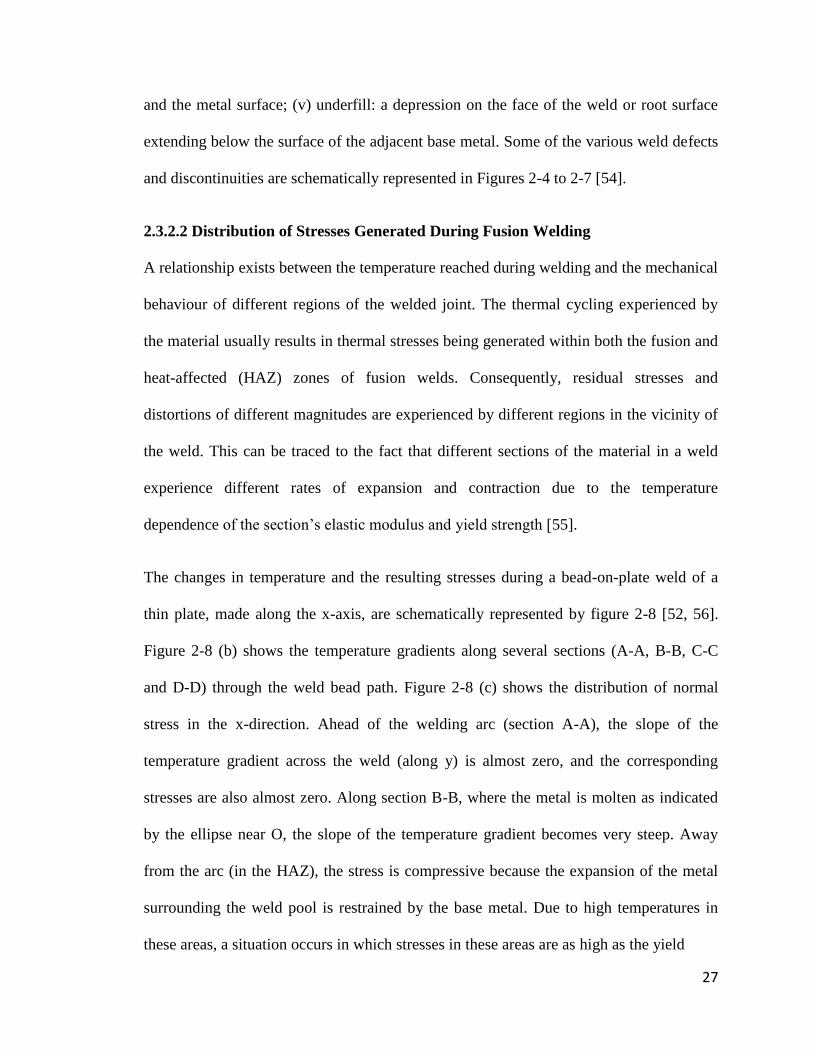
27
and the metal surface; (v) underfill: a depression on the face of the weld or root surface
extending below the surface of the adjacent base metal. Some of the various weld defects
and discontinuities are schematically represented in Figures 2-4 to 2-7 [54].
2.3.2.2 Distribution of Stresses Generated During Fusion Welding
A relationship exists between the temperature reached during welding and the mechanical
behaviour of different regions of the welded joint. The thermal cycling experienced by
the material usually results in thermal stresses being generated within both the fusion and
heat-affected (HAZ) zones of fusion welds. Consequently, residual stresses and
distortions of different magnitudes are experienced by different regions in the vicinity of
the weld. This can be traced to the fact that different sections of the material in a weld
experience different rates of expansion and contraction due to the temperature
dependence of the section‟s elastic modulus and yield strength [55].
The changes in temperature and the resulting stresses during a bead-on-plate weld of a
thin plate, made along the x-axis, are schematically represented by figure 2-8 [52, 56].
Figure 2-8 (b) shows the temperature gradients along several sections (A-A, B-B, C-C
and D-D) through the weld bead path. Figure 2-8 (c) shows the distribution of normal
stress in the x-direction. Ahead of the welding arc (section A-A), the slope of the
temperature gradient across the weld (along y) is almost zero, and the corresponding
stresses are also almost zero. Along section B-B, where the metal is molten as indicated
by the ellipse near O, the slope of the temperature gradient becomes very steep. Away
from the arc (in the HAZ), the stress is compressive because the expansion of the metal
surrounding the weld pool is restrained by the base metal. Due to high temperatures in
these areas, a situation occurs in which stresses in these areas are as high as the yield

28
Figure 2 - 4: Types of gas porosity commonly found in weld metals (a) Uniformly
scattered porosity (b) Cluster porosity (c) Linear porosity (d) Elongated porosity
Source: ASM Handbook Volume 6: Welding, Brazing and Soldering,
Copyright 1993. Reprinted with permission from ASM International (17 May, 2013). All
rights reserved. www.asminternational.org

29
Figure 2 - 5: Lack of fusion in (a) a single-V-groove weld and (b) double-V-groove
weld. Lack of penetration in (c) a single-V-groove weld and (d) a double-V-groove weld
Source: ASM Handbook Volume 6: Welding, Brazing and Soldering,
Copyright 1993. Reprinted with permission from ASM International (17 May, 2013). All
rights reserved. www.asminternational.org

30
Figure 2 - 6: Weld discontinuities affecting weld shape and contour. (a) Undercut and
overlapping in a fillet weld. (b) Undercut and overlapping in a groove weld. (c) and (d)
Underfill in groove welds
Source: ASM Handbook Volume 6: Welding, Brazing and Soldering,
Copyright 1993. Reprinted with permission from ASM International (17 May, 2013). All
rights reserved. www.asminternational.org

31
Figure 2 - 7: Identification of cracks according to location in weld and base metal. 1,
crater crack in weld metal; 2, transverse crack in weld metal; 3, transverse crack in HAZ;
4, longitudinal crack in weld metal; 5, toe crack in base metal; 6, underbead crack in base
metal; 7, fusion-line crack; 8, root crack in weld metal; 9, hat crack in weld metal
Source: ASM Handbook Volume 6: Welding, Brazing and Soldering,
Copyright 1993. Reprinted with permission from ASM International (17 May, 2013). All
rights reserved. www.asminternational.org

32
Figure 2 - 8: Schematic representation of changes in temperature and stresses during
welding: (a) Weld (b) Temperature changes (c) Stress distribution
Source: K. Masubuchi, Analysis of Welded Structures, 1980, ISBN 0-08-0261299.
Reprinted with permission from the author, Koichi Masubuchi (30 June, 2013)

33
stress of the base metal at the corresponding temperature. Therefore, the magnitude of
compressive stress passes through a maximum with increasing distance or with
decreasing temperature from the weld. However, tensile stresses occur in regions far
away from the welding arc. Somewhat behind the welding arc (C-C), the temperature
gradient slope becomes less steep since the weld-metal and the base-metal have cooled.
As they shrink during cooling, tensile stresses are generated in regions in, and adjacent
to, the weld while the stresses become compressive as the distance from the weld
increases. Along section D-D, some longer distance behind the welding arc, the
temperature gradient slope approaches zero again and high tensile stresses exist in, and
adjacent to, the weld while compressive stresses exist in areas away from the weld.
The development of tensile stresses in the fusion and heat-affected (HAZ) zones of fusion
welds during weld cooling plays an important role in weld cracking. This is a major
mechanical factor that contributes significantly to cracking during conventional fusion
welding of superalloys. Apart from on-cooling tensile stresses, other metallurgical factors
necessary for cracking are equally important. Cracking in welded materials generally
occurs in the fusion zone (solidification cracking) and/or in the heat-affected zone (HAZ
Cracking). These are discussed next.
2.3.2.3 Solidification Cracking
Solidification cracking, which is observed frequently in castings and ingots, can also
occur in weld deposits of fusion welds during cooling. It occurs predominantly at the
weld centerline or between columnar grains that form on solidification of the weld metal.
Solidification cracking is a type of cracking that occurs during the terminal stage of
solidification, when the tensile stresses developed across adjacent grains exceed the

34
strength of the almost completely solidified weld metal [57-59]. During solidification, the
weld metal tends to contract because of both solidification shrinkage and thermal
contraction. Though the base metal also contracts, it does not contract as much as the
weld metal because it is neither melted nor heated as much as the weld metal on the
average. The contraction of the solidifying metal can therefore be hindered by the base
metal, especially if the workpiece is constrained and cannot contract freely.
Consequently, tensile stresses develop in the solidifying weld metal. A point is reached
when the semi-solid material can no longer accommodate the thermal shrinkage strains
associated with weld solidification and cooling. In order to relieve the accumulating
strains, cracks form at susceptible sites such as solidification grain boundaries and
interdendritic regions, which are at least partially wetted [60].
The factors affecting solidification cracking susceptibility of weld metals can be either
metallurgical or mechanical in nature. Some of the metallurgical factors include:
a. The solidification temperature range: the wider the solidification (freezing)
temperature range, the larger the S+L region in the weld metal or mushy zone and
thus the larger the area that is weak and susceptible to solidification cracking. The
larger S+L region can result from the presence of undesirable impurities such as
sulphur and phosphorus, or intentionally added alloying elements [53]
b. The amount and distribution of liquid at the terminal stage of solidification:
maximum crack susceptibility occurs somewhere between the composition of a pure
metal and the composition of a highly alloyed metal. A pure metal is not susceptible
to cracking because there is no low-melting-point eutectic present at the grain

35
boundary to cause solidification cracking. In highly alloyed material, on the other
hand, the eutectic liquid between the grains can be abundant enough to heal incipient
cracks. Somewhere in between these composition levels, however, the amount of
liquid between grains can be just large enough to form a thin, continuous
intergranular film to make the materials susceptible to solidification cracking but
without extra liquid for healing the cracks [53].
c. The ductility of the solidifying weld metal: the less ductile a solidifying weld metal
is, the more likely it will crack during solidification [53, 61]
d. The grain morphology of weld metal: Fine equiaxed grains are often less susceptible
to solidification cracking than coarse columnar grains [61]. This has been attributed
to the fact that fine equiaxed grains can deform to accommodate contraction strains
more easily, that is, they are more ductile, than columnar grains. Liquid feeding and
healing of incipient cracks can also be more effective in fine-grained material, and
the grain boundary area is greater, which reduces the concentration of low-melting-
point segregates at the grain boundaries.
The mechanical factors affecting solidification cracking include residual stresses and
joint geometry. Though the metallurgical factors described earlier are very important for
the occurrence of solidification cracking, no cracking can occur without the presence of
tensile stresses acting on adjacent grains during solidification. The thermal cycle of the
welding process always results in residual stresses in the weld metal. These stresses can
be due to thermal contraction or solidification shrinkage or both. The severity of the
stresses depends on the degree of restraint offered by the welded joint. Generally, the

36
thicker or stronger the plates being welded, the higher is the restraint. The higher is the
restraint; greater is the magnitude of the residual stress.
The mechanism of solidification cracking can be illustrated with Figure 2-9 [62]. It is
generally understood that the partitioning and rejection of alloying elements at the
columnar grain boundaries and ahead of the advancing solid-liquid interface causes
marked segregation. The segregates subsequently form low-melting phases or eutectics
with the metal to produce highly wetting films at grain boundaries as illustrated. The
alloying elements that are most-likely to segregate this way have characteristics
including: low partition coefficients, ready formation of low-melting-point compounds or
eutectics with the base alloy, and low wetting angle with the metal and thus possess the
ability to spread along grain boundaries. As a result of these, the boundaries are
weakened and cracks form under the influence of the tensile residual stresses that are
generated during cooling of welds [55].
2.3.2.4 Heat-Affected Zone (HAZ) Cracking
Liquid formed on grain boundaries in the heat-affected zone (HAZ) during fusion
welding can wet the grain boundaries and spread along them to form a continuous film.
When this formation of continuous intergranular film is accompanied by sufficient tensile
thermal stresses, cracks can form along the grain boundaries and extend into the fusion
zone. Such cracking can be referred to as liquation cracking, hot cracking or
microfissuring in the HAZ. Figure 2-10 [62] illustrates the formation of liquation cracks
in a typical alloy. While the weld deposit is still liquid, compressive stresses tend to close
up liquation cracks. However, the stresses (or strains) in the HAZ become tensile as the
melt solidifies and these open up cracks [55].

37
Figure 2 - 9: Schematic illustration of the mechanism of solidification cracking.
Source: R.G. Baker, Philosophical Transactions of the Royal Society of London, Series
A: Mathematical and Physical Sciences, Vol. 282 No 1307 (1976) pp.207-223. Reprinted
with permission from The Royal Society (21 May, 2013)

38
Figure 2 - 10: Schematic diagram illustrating liquation cracking
Source: R.G. Baker, Philosophical Transactions of the Royal Society of London, Series
A: Mathematical and Physical Sciences, Vol. 282 No 1307 (1976) pp.207-223. Reprinted
with permission from The Royal Society (21 May, 2013)

39
It is known that grain boundary liquation can occur by either supersolidus melting or by
non-equilibrium sub-solidus melting. Non-equilibrium sub-solidus melting is particularly
more harmful due to its ability to widen the temperature range over which a weldment
remains liquid and thus increase the material‟s susceptibility to HAZ liquation cracking
[63]. The sub-solidus melting can occur by two main mechanisms, namely:
1. Constitutional liquation of second phase particles.
2. Segregation of melting point suppressing elements on the grain boundaries during
solidification and thermal processing and during pre-weld heat treatment.
2.3.2.4.1 Constitutional Liquation Mechanism
Constitutional liquation theory was first proposed and explained in the literature by Pepe
and Savage in 1967, when they observed liquation of titanium sulphide particles in 18-Ni
maraging steels [64]. When an alloy, having a certain volume fraction of an intermetallic
particle AxBy at room temperature, is heated rapidly to temperatures equal to or above the
eutectic transformation temperature, constitutional liquation of AxBy could occur if the
particle survives to the eutectic temperature during heating. This theory has been
subsequently used to explain non-equilibrium sub-solidus melting of second phases in
different alloys during fusion welding, which is generally known to cause HAZ liquation
cracking. Examples, as observed by different researchers, include the constitutional
liquation of: M3B2 in Udimet 700 [65], Cr7C3 and Ti(CN) in Inconel 600 [66], TiS in 18-
Ni maraging steel [64], TiC in austenitic alloy A286 [67], M6C in Hasteloy X [65], MC
Carbide and MNP Phosphides in Incoloy 903 [68], NbC and Laves phase in Inconel 718
[69], and MC Carbide in Allvac 718Plus® [70].

40
The Constitutional Liquation Theory
The constitutional liquation of a precipitate particle in a hypothetical binary alloy system
can be illustrated by the constitutional phase diagram of figure 2-11 [64]. The alloy, of
nominal composition Co, when heated progressively from T1 to T4, exhibits different
behavior for an infinitely slow heating rate and for an extremely rapid heating rate. At
temperature T1, the alloy of composition Co consists of the intermetallic compound AxBy,
distributed as a second-phase precipitate in the α solid solution. Under an equilibrium
solidification condition corresponding to an infinitely slow heating rate, the solubility of
B in the matrix increases as the temperature is increased. At T2, the last remaining AxBy
dissolves, converting the alloy to a homogeneous single phase solid solution of
composition Co. No further changes occur as the temperature further increases from T2 to
just below T5. At T5, which is the equilibrium solidus of the alloy, the first infinitesimal
amount of liquid of composition corresponding to point c is formed. Therefore, under an
equilibrium condition, the two phase alloy is gradually converted to a single phase alloy.
It remains a single phase until the first melting occurs at the equilibrium solidus of the
alloy.
The dissolution of AxBy under non-equilibrium solidification condition, which
corresponds to an extremely rapid heating rate, significantly departs from that that occurs
under equilibrium solidification. The disappearance of AxBy upon heating requires its
dissociation and subsequently the accommodation of the excess component of B, which
is liberated as additional solute in the surrounding matrix. The overall rate of dissolution
of AxBy occurs at a finite rate, which may be limited by either or both of the dissociation
or accommodation process step. As the heating rate is increased, a critical heating rate

41
Figure 2 - 11: Schematic diagram of a portion of a hypothetical constitutional diagram
for an alloy system exhibiting the behaviour necessary for constitutional liquation.
Source: J.J. Pepe and W.F. Savage, Weld. J., Vo146 (No. 9), 1967, p 411-s. Reprinted
with permission from the American Welding Society (2 August, 2013)

42
will be reached above which the time required to raise the temperature to the equilibrium
solidus temperature will be insufficient to achieve complete dissolution of AxBy. At this
critical heating rate and all heating rates above it, the dissociation and diffusion process
steps will occur at finite rates. The equilibrium structure of AxBy as a function of
temperature is represented by the vertical line emanating from Co in figure 2-11. Since
the system would be striving to maintain equilibrium, any departure from an equilibrium
structure due to rapid heating results in solute redistribution. For a spherical AxBy
precipitate and a heating rate above the critical heating rate, the changes expected in the
vicinity of AxBy during heating to temperatures of T3, Te and T4, respectively, can be
illustrated by figures 2-12a to 2-12c. During heating to T3, AxBy dissociates since at T3,
AxBy is unstable with respect to a single phase solid solution of composition Co. AxBy
shrinks somewhat from its original volume to a smaller volume as represented by dashed
and solid circles, respectively, in figure 2-12a. The B atoms liberated diffuse into the
adjacent α matrix. However, figure 2-11 shows that AxBy must be in contact with the
matrix of composition m if the two phases are to co-exist. It is therefore necessary that a
concentration gradient exist in the α matrix, such that a maximum concentration value, m,
exists at the AxBy phase interface, which decreases toward the original matrix
composition, o, at the interior of the α phase. In order to maintain a material balance, the
area of the double cross-hatched region of figure 2-12a must be equal to the area of the
single cross-hatched region. The concentration gradient slope would be dependent on:
1. The heating rate: the faster the heating rate is, the steeper the concentration
gradient

43
Figure 2 - 12: Schematic representation of the concentration gradients at various
temperatures during formation of constitutional liquation
Source: J.J. Pepe and W.F. Savage, Weld. J., Vo146 (No. 9), 1967, p 411-s. Reprinted
with permission from the American Welding Society (2 August, 2013)

44
2. The diffusivity of solute: the faster the diffusivity of solutes, the shallower the
concentration gradient
3. The relative ease with which the solute atoms are accommodated by each
successive single phase region in the diffusion couple
AxBy continues to dissociate during heating from T3 to Te, the particle size continues to
decrease as represented in figure 2-12b, where the dashed and solid circles represent the
location of AxBy interface at T3 and Te, respectively. At the eutectic temperature, Te, the
composition corresponding to point e permits the formation of a single phase liquid at the
AxBy interface, thus, the undissociated portion of AxBy is surrounded by a liquid phase of
composition e, which, in turn, is surrounded by the α matrix. Figure 2-12b shows the
solute distribution in the three phases co-existing at temperature Te. On further heating to
T4, additional time is allowed for the dissociation of AxBy. The expected solute
distribution at T4 is shown by figure 2-12c. Upon heating above Te, the equilibrium
solubility of α phase decreases along the solidus line “akl”. Therefore at T4, the
concentration of the solute in solid solution and the liquid film in contact with one
another correspond to k and d, respectively. Each particle of AxBy remaining undissolved
at T4 is surrounded by a liquid film of variable composition ranging from “f” at the AxBy
interface to “d” at the matrix interface. This causes localized melting under non-
equilibrium heating rates at temperatures between Te and T5, a phenomenon termed as
constitutional liquation. Therefore, constitutional liquation occurs under rapid heating
and results in the formation of solute-rich liquid pools at temperatures well below the
equilibrium solidus of the alloy [64]. Interactions between these liquated regions and the

45
grain boundaries during fusion welding could establish a microstructure that is sensitive
to intergranular liquation cracking.
2.3.2.4.2 Grain Boundary Segregation Mechanism
Grain boundary segregation is another mechanism for grain boundary liquation. It occurs
by the segregation of melting point suppressant elements to grain boundaries, which
reduces the melting temperature of the grain boundary material relative to the
surrounding matrix. For grain boundary liquation cracking to occur by this mechanism,
grain boundary segregation must take place first. Non-equilibrium sub-solidus grain
boundary melting then occurs in the HAZ during welding at temperatures which are
above the reduced melting temperature of the grain boundary material [63]. The effect of
segregation of solutes and the close relationship between segregation and the weldability
of nickel-based superalloys, where segregation was found to alter the liquid wettability of
grain boundaries, has been studied [71]. The presence of solutes in the grain boundary
liquid was observed to have lowered the solidification range of the liquid and contributed
to HAZ microfissuring.
Grain Boundary Segregation Theory
Segregation of impurities on grain boundaries before welding can be induced by either
equilibrium segregation [72-75] or non-equilibrium segregation [76-80]. Equilibrium
grain boundary segregation occurs by the movement of solutes from the bulk of the alloy
to grain boundaries when the material is held at a sufficiently high temperature that can
promote an appreciable diffusion of solutes. The solute atoms are absorbed to reduce the
interfacial free energy of the loosely packed grain boundary region. Impurity atoms can
also segregate from the bulk alloy to other loosely packed sites such as free surfaces,

46
phase boundaries, stacking faults and precipitate/matrix interfaces. The driving force for
equilibrium grain boundary segregation is a reduction in the grain boundary free energy.
As the temperature of the isothermal heat treatments increases, the level of segregation
decreases. Equilibrium grain boundary segregation is restricted to a few atoms layers of
the grain boundary and the total amount is usually of the order of a few monolayers.
Non-equilibrium segregation occurs during cooling from the thermal treatment
temperature. In addition to the equilibrium concentration of vacancies generated and
distributed during elevated temperature heat treatment, some vacancy-solute complexes
can also form as a result of positive binding energy between the solute atom and vacancy.
The diffusion coefficient of the solute-vacancy complex exceeds that of the solute alone.
During cooling to lower temperatures, supersaturation of vacancy concentration occurs in
the matrix, and the grain boundaries can act as sinks for vacancies. A concentration
gradient of vacancies develops near the grain boundaries and vacancies within diffusion
range of the grain tend to migrate to the grain boundaries. Vacancy diffusion towards the
grain boundaries tends to drag solute-vacancy complexes towards the boundaries,
producing a solute-rich grain boundary region. This process is thermodynamically driven
by the decrease in free energy associated with the annihilation of excess vacancies at the
grain boundary sinks [81]. The degree of non-equilibrium segregation has been found to
depend on the starting temperature, cooling rate, bulk concentration of solutes and the
binding energy between solute atoms and vacancies [82-85]. An increase in thermal
treatment temperature increases equilibrium concentration of vacancies and the degree of
segregation increases. If sufficient time is not available for the diffusion of complexes to
grain boundaries to occur when the cooling rate is high, the degree of segregation will be

47
reduced. On the other hand, if the cooling rate is very slow, causing a gradient in
concentration of solute atoms between the grain boundary and the grain interior, the
segregated solute atoms may diffuse back to the grain interiors, thereby eliminating
segregation [71].
2.3.3 Weldability Testing
As discussed earlier, welding processes usually have effects on the properties and
characteristics of materials. These characteristics include base-metal and weld metal
ductility and cracking susceptibility, weld penetration and weld shape [86]. Weldability
testing is used to evaluate the properties and characteristics that developed in materials
during welding. Weldability tests are intended to evaluate actual service conditions
through the responses of the base material to different welding conditions or simulated
welding conditions. Some of the weldability testing methods are described next.
2.3.3.1 Self-Restraint Tests
These tests utilize the restraint within the specimen, without external loading, to cause
cracking in the weld or base metal [86]. The specimen used for testing is designed to
produce variable restraint on the weld joint, resulting in cracking. An example of self-
restraint test is the Lehigh Restraint Test for hot and cold cracks, which is illustrated in
Figure 2-13. The test is used to compare qualitatively the degree of restraint at which
cracking occurs in welds during cooling. Lehigh test uses a plate with slots machined into
the sides and ends. A single pass weld is produced along a groove that is previously
machined along the centerline of the plate. The restraint from the plate and slots produces
various levels of cracking in the weld. The level of restraint is altered by changing the
length of the slots [87, 88]. The restraint is measured as 2x, where x is the distance from

48
Figure 2 - 13: Schematic showing slotted plate specifications for Lehigh restraint test
Source: R.D. Stout, S.S. Tor, L.J. McGeady and G.E. Doan, Weld. J., Vo1 26 (No. 11),
1947, p 673-s. Reprinted with permission from the American Welding Society (2 August,
2013)

49
the centerline of the weld groove to the bottom of the slots, as shown in Figure 2-13.
Several samples with different lengths of slots are usually welded. A threshold level of
restraint is determined as the width that is just sufficient to cause cracking.
2.3.3.2 Externally Loaded Tests
These tests involve the application of an external load to the specimen during welding.
The externally applied load is usually varied to alter the stress state and thus the severity
of cracking in the specimen [86]. An example of externally loaded tests is the Varestraint
Test (Hot Crack Test), which was developed at Rensselaer Polytechnic Institute [89] and
is the most common test used to evaluate hot crack sensitivity. In Varestraint (variable
restraint) test, one end of a rectangular bar (typically 205 by 50 by 6.4 mm) is firmly
mounted in fixed position while the opposite end is attached to a hydraulic or pneumatic
plunger (Figure 2-14). A weld (usually GTA weld) is produced on the top side of the
plate along its longitudinal centerline, beginning at the unsupported end and moving
towards the fixed end. When the arc reaches a pre-determined location over a die block,
the plate is bent to conform to the radius of the die block. This bending induces an
augmented longitudinal strain on the welded surface of the specimen. In order to
characterize the strain level at which cracking begins in a material, various die blocks
with different radii can be used. For material evaluation, however, a single die block of
known radius, which will produce cracking in all samples, is used. Hot cracks usually
form along the edge of the weld pool and in the HAZ. The mean values of total crack
length, number of cracks, or maximum crack length in duplicate samples of each material
are used as a quantitative means of evaluating base metal weldability [87].

50
Figure 2 - 14: Set up and sample specifications for Varestraint test
Source: W.F. Savage and C.D. Lundin, Weld. J., Vo1 44 (No. 10), 1965, p 433-s.
Reprinted with permission from the American Welding Society (2 August, 2013)

51
2.3.3.3 Gleeble Testing
The Gleeble is a thermomechanical device that has been used in a wide range of
applications involving study of a variety of materials problems [86]. The Gleeble has a
long and proven history in the study of research-level metallurgical phenomena and also
for production-level materials testing to predict service behavior. Applications of Gleeble
testing include studies of hot ductility [90, 91], mechanical properties of the weld HAZ
[92, 93], continuous cooling transformation diagrams [94, 95], stress relief cracking [96],
precipitation kinetics [97], basic weldability [98, 99], strain age cracking [100],
constitutional liquation [22, 24, 64], and so on. The applications of Gleeble testing is also
not limited to welding, but can be used in the evaluation of other material properties such
as thermomechanical fatigue and other forms of thermomechanical testing.
A Schematic diagram showing the components of the Gleeble is shown in Figure 2-15
[101]. The Gleeble system has a full computer interface. It is readily programmed to
provide reference signals for closed loop control of both thermal and mechanical
operations. The flow of low frequency alternating current in the specimen is used to
accomplish heating at rates up to 20,000oC/s. A fine wire thermocouple percussion
welded to the specimen surface provides the feedback signal necessary for closed-loop
control. The Gleeble can be used to simulate very small, hard-to-study regions in
weldments by generating large volumes of microstructure.
2.3.3.4 Measurement of Total Crack Length
The weldability of a metallic material can also be assessed by the measurement of total
crack length in experimental specimens [102]. In this method, the experimental
specimens are welded under the same condition (materials preparation and welding

52
Figure 2 - 15: Gleeble test method. (a) Primary components (b) Close-up view of
resistance heater (c) Programmed thermal cycle
Source: Industrial Heating, Vol. 53 (No 12) Dec. 1986, p.28. Reprinted with permission
from Industrial Heating (31 July, 2013)

53
parameters) required for the actual weldments. The specimens are then sectioned
transverse to the welding direction. The total crack length in each section of the specimen
is determined by direct microscopic measurements. Cracking susceptibility in the welded
material can be evaluated using the total crack length in two ways. Firstly, the total crack
lengths (TCLs) obtained from different specimens can be compared to assess weldability.
For this method to be valid, it is required that the specimens are welded using the same
set of welding parameters, which is expected to produce approximately the same total
area of the HAZ. The crack length in a transverse section of the specimen can be given as
)32.......(......................2,1
n
k
nlL
where l is the length of individual crack in a section and n is the number of cracks in a
section. For statistical correctness, the welded specimens are usually sectioned into about
10 pieces or more and the sum of L values from each section is calculated to determine
the TCL. The TCL is given as
)42.......(..............................10
1i
iLTCL
Secondly, if the specimens are welded using different sets of welding parameters or under
different welding conditions, the calculation of cracking index (CI) may be required. The
CI is a measure of the total crack length normalized with the total area of the HAZ, given
by
)52.........(....................10
1Ti
iALCI

54
AT is the total area of the HAZ, measured from all the sections. The CI provides a
quantitative assessment of the weldability of a material in terms of the crack length per
unit area. Other measurements that can be derived from the TCL measurement include
number of cracks, maximum crack length (MCL), average total crack length (ATCL), etc.
Advancements in welding research and continuous, rigorous effort in solving major
weldability problems in materials led to the invention of laser-arc hybrid welding. This
relatively new development is discussed in details in the next section.
2.4 The Emergence of Laser-Arc Hybrid Welding
Laser-arc hybrid welding is a relatively new joining technology in comparison with other
conventional fusion welding processes. It combines the best characteristics of laser
welding with those of conventional arc welding processes [15]. Laser welding and arc
welding have been used separately for various industrial applications, and both processes
possess their specific advantages and limitations. A major idea behind the combination of
these two welding processes in laser-arc hybrid welding process is the successful
integration of the advantages of both. Laser-arc hybrid welding is also acknowledged to
have been designed to overcome problems such as cracking, porosity and brittle phase
formation, which are usually encountered during both laser and arc welding [10]. In
laser-arc hybrid welding, a laser beam interacts in the same molten pool as the molten
pool created by a secondary heat source (in this case, an electric arc) [11]. Both laser
beam and arc simultaneously act on the welding zone, and each affects and complements
the other [12]. This synergistic effect of laser beam and arc can result in quality
advantage, shorter fabrication times, higher productivity and improved cost efficiency
[103, 104].

55
A review of laser-arc hybrid welding process revealed that this method has been known
since 1970s [103, 105]. The laser-arc hybrid welding concept was first introduced by
Steen et al [7-9], who performed experiments that combined CO2 laser beam with
tungsten inert-gas (TIG) for welding and cutting materials [13]. These first attempts,
whereby an electric arc is rooted into exactly the same location on a work piece surface at
which a laser beam strikes [7, 9], were made at the Department of Metallurgy and
Materials Science, Imperial College of Science and Technology, London. According to
Bagger and Olsen [11], although the experiments performed by Steen et al revealed
several advantages over other processes, their results did not immediately encourage
extensive activities and the development of the process progressed relatively slowly. One
of the suggested reasons for this slow development is that laser welding process itself was
yet to be developed into an industrially viable process [11]. However, the development of
reliable high power lasers in 1980s and the wider industrial acceptance in the 1990s
resulted in matured, economic and user friendly laser welding process [11]. In the 1990s,
developments in welding research led to the reintroduction of laser-arc hybrid welding,
with the combination of high power lasers as the primary heat source and an electric arc
as the secondary heat source. Laser-arc hybrid welding also gained industrial acceptance
in the 1990s, and several combinations of heat sources and different process
arrangements were examined [13]. At present, laser-arc hybrid welding is making an
important impact in the welding industry and is now being used for manufacturing
components and assemblies in a variety of industrial applications. Some leading global
manufacturers in developed countries, such as USA, Germany and UK, are now adopting
this fast-growing technology in actual daily production.

56
2.4.1 Laser Beam Welding
2.4.1.1 The Laser Beam Welding Process
Lasers have been used in joining materials by impinging the heat obtained from the
amplification of concentrated coherent light beam on the surfaces to be joined [30]. The
beam is usually focused by optical elements (mirrors or lenses) to a small spot size to
produce a controlled high power density, which melts the metal and, in case of deep
penetration welds, vaporizes some of it. A fusion zone forms which on solidification
results in a weld joint. The two major laser technologies, which were invented in the
1960s, are: (1) the solid-state Nd:YAG laser, with emission of light energy at a
wavelength of 1064 nm, and (2) the CO2 laser, with emission at a wavelength of 10.6 μm.
The first commercially available lasers were low power pulsed Nd:YAG systems and 100
W CO2 lasers. Nowadays, up to 8 kW continuous wave Nd:YAG and up to 20 kW off-
the-shelf CO2 lasers are commercially available [106]. In a solid-state laser, a single
crystal such as yttrium-aluminum-garnet (YAG) is doped with small concentrations of
transition elements or rare earth elements like neodymium. Selective excitation of the
electrons of the dopant element can occur upon exposure to high-intensity flash lamps,
which subsequently produces laser beams when the excited electrons return to their
normal energy states. CO2 laser, which produces higher power than solid-state laser, is a
gas laser produced from the mixture of CO2, N2 and He. The gas mixture is continuously
excited by electrodes connected to the power supply, producing a laser beam. Nd:YAG
and CO2 lasers have been the two main types of industrial lasers used at high powers for
deep penetration.

57
The major difference between Nd:YAG and CO2 lasers, in terms of materials processing,
is the difference in the wavelength of light emitted [107]. Nd:YAG lasers produce light of
1.06 μm wavelength that can be transmitted to the workpiece by fibre optical cable.
However, CO2 produces light of 10.64 μm wavelength that must be transmitted to the
workpiece by reflective and transmissive optical systems, which are more cumbersome,
making CO2 laser less flexible [107]. Fibre laser, which belongs to the large group of
solid state laser, was recently developed. It consists of a glass fibre doped with Ytterbium
and optically pumped by diodes, which delivers the beam with wavelength of 1070 +/-
5nm [108]. Both solid-state laser and gas laser have been combined with arc welding
processes in laser-arc hybrid welding.
The emitted electromagnetic (nearly monochromatic) laser light is usually concentrated
to very small (few hundreds of micrometer diameter) spot sizes on the material. In a
review work by Mahle and Beyer [109], it was suggested that the most important factors
that determine the intensity of the spot at the surface of the material being welded (or
processed) are the available optical output power PL, the wavelength λ of the emitted
radiation and the beam parameter product BPP (a measure of beam focusability). For the
case of a circular beam with radius wo, the average value of the intensity, IL,o is defined
as:
)62........(....................2
,
,
o
L
oL
LoL
w
P
A
PI
AL,o is the cross-sectional area of the beam. wo is a function of the focal length of the lens
used for focussing, the diameter of the initial beam before focusing and the focusability

58
parameter BPP. A detailed treatment of wo for both Gaussian (diffraction-limited) and
non-Gaussian (actual) beam is available in the literature [109]
2.4.1.2 Laser-Material Interaction
When a laser beam interacts with the elastically bound electrons in a material, it induces
vibration of the electrons. Some of the incident energy of the laser beam is absorbed in
the material by the bound electrons and some is reflected by free electrons. The portion of
the energy absorbed is determined by the type of material, wavelength of the beam,
temperature, surface condition and angle of incidence [106]. The induced vibration of
bound electrons in the constrained lattice structure is transmitted through the material and
observed as heat. The supply of an amount of heat energy that can effectively overcome
mechanical strength in the material bonds results in melting of the material. Welding
occurs when the heat source used to melt a common region between two work pieces is
retracted and the molten zone is allowed to cool and solidify [106]. There are two modes
of laser welding; namely conduction mode and keyhole mode. In conduction mode
welding, the heat produced by the laser beam is controlled to allow melting without any
significant evaporation. This can be achieved by operating the laser beam out of focus,
which creates a balance between the heat produced in the material and the heat conducted
away from the interaction spot. When the irradiance of the laser beam is high, the heat
produced can be sufficient to break atomic bonds, resulting in vaporization. A still higher
intensity can cause electrons to be removed from the vaporized metal atoms and from
gases in the interaction zone, resulting in plasma generation. The high temperature
vapour and plasma will tend to expand, thus generating a recoil force that pushes on the
surrounding molten material, creating a keyhole.

59
Keyhole welding favours much higher penetration compared with conduction mode
welding due to additional opportunities for laser absorption through multiple reflections
in the keyhole. The temperature of vapour and plasma in the keyhole can be extremely
high, approximately 2000 K for Nd:YAG and 6000 – 10,000 K for CO2 welding [110].
Illustrations of conduction mode and keyhole mode welding are provided in Figure 2-16
[109]. Conventionally, laser beam welding is carried out without filler alloys. The weld
zone and adjacent regions are usually shielded from the atmosphere by a blanket of inert
gas. Argon, helium or mixtures of the two gases are typically used.
2.4.1.3 Benefits of Laser Beam Welding
Laser welding is capable of joining materials in applications with limited accessibility
such as welding of gears, applications that require high welding speed such as
longitudinal seams on pipes, and applications that require precisely controlled heat input
such as components for electronics [111]. The major benefit of using laser welding lies in
its high power density. This enables high welding speeds with deep penetration, and
narrow fusion and heat-affected zones [10, 18]. In laser welding, the ratio of the depth of
penetration to the weld width is high [112]. Also, the resultant low heat input welds
produce low residual stresses and very little structural distortion, such that the effect of
heat on the material is minimal, while achieving high welding speed at the same time [10,
18, 112]. Single pass welding of materials with thick sections is possible [10]. The
process is also suitable for welding dissimilar parts that vary greatly in mass and size.
Vacuum and X-ray shielding are generally not required.
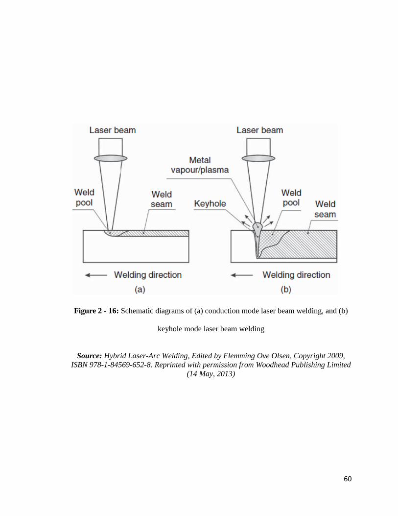
60
Figure 2 - 16: Schematic diagrams of (a) conduction mode laser beam welding, and (b)
keyhole mode laser beam welding
Source: Hybrid Laser-Arc Welding, Edited by Flemming Ove Olsen, Copyright 2009,
ISBN 978-1-84569-652-8. Reprinted with permission from Woodhead Publishing Limited
(14 May, 2013)

61
2.4.1.4 Shortcomings of Laser beam Welding
The limitations of laser welding include high tooling and operating cost, high
requirements for part positioning and clamping, high welding speeds leading to high
solidification rates and subsequent porosity and cracking [11, 13]. Keyhole instability and
formation of brittle phases also affect the weld quality [10]. The ability of laser welding
process to bridge root openings is low as a consequence of its small focus diameter [103,
113]. The inability to bridge wide gaps necessitates precision assembly of parts, which is
usually difficult to attain in production [90]. Another major drawback in the use of laser
beam welding is the very high reflectivity of a laser beam by the metal surface, which
reduces the amount of penetrating beam. This makes it difficult to join highly reflective
materials such as aluminum, copper and gold by laser welding [11]. The low energy
efficiency of lasers can also be considered as a disadvantage, although recent
advancements have led to the invention of fibre lasers and direct diode lasers that offer up
to 30 % (or higher) wall plug efficiency [109].
2.4.2 Description of Arc Welding Processes
As mentioned earlier, arc welding uses an arc that is struck between an electrode and the
workpiece, to generate heat that melts the filler (which could sometimes be the electrode)
and the base metal. This produces a molten pool under the protection of an inert gas
blanket. As the heat source retreats from the molten pool area, the pool solidifies,
forming a weld bead and a heat-affected zone (HAZ) adjacent to the weld bead. In
principle, arc welding is based on an electric gas discharge under atmospheric pressure
conditions between two open terminals, namely the welding electrode and the work
piece. The gaseous zone between the welding electrode and the work piece is partially

62
ionized, resulting in the generation of visible plasma arc, which closes the welding
current circuit and ensures continuous transfer of electrical energy between the electrode
and the work piece. Current is transferred by the flow of electrons from the negatively
charged cathode to the positively charged anode. Both positive and negative polarities
can be applied depending on the work piece material and the amount of heat input
required. Arc welding is still the most applied welding heat source, with gas metal arc
welding (GMAW) and tungsten inert gas (TIG) welding being especially very popular
[109].
Gas Metal Arc Welding (GMAW)
GMAW joins metals by using a high temperature ionized column of gas (or plasma) that
spans between a consumable electrode and the work piece. The diameter of the electrode
is typically between 0.89 and 1.6 mm. The arc temperature, which is usually in the order
of 6600oC, is sustained by high current (between 100 and 450 A) that is provided by a
low potential (15 to 35 V) welding power supply. A typical GMAW welding set-up is
illustrated in Figure 2-17 [106]. The electrical voltage and current are provided by the
power supply. The current is fed through electrical cables to the contact tip, which is
connected to the consumable filler wire. The electrical circuit is completed by connecting
the work piece to the other lead from the power supply. The filler wire is fed into the
welding torch by means of a wire feeder. The shielding gas is also fed coaxially through
the torch around the contact tip. The welding torch can be either manually operated or
connected to a robot. The various welding modes available in GMAW include short
circuit, globular, spray and pulsed spray transfer modes.

63
Figure 2 - 17: Schematic of a typical GMAW set-up
Source: Hybrid Laser-Arc Welding, Edited by Flemming Ove Olsen, Copyright 2009,
ISBN 978-1-84569-652-8. Reprinted with permission from Woodhead Publishing Limited
(14 May, 2013)

64
Tungsten Inert Gas (TIG) Welding
In TIG, which is also usually called Gas Tungsten Arc Welding (GTAW), the heat is
produced between non-consumable tungsten electrode and the metal work piece [53]. The
electrode, weld pool, arc and adjacent heated work areas of the work piece are protected
from atmospheric contamination by a gaseous shield, which is provided by a stream of
gas (usually an inert gas) or a mixture of gases. The torch holding the tungsten electrode
is connected to the shielding gas cylinder as well as one terminal of the power source,
with the tungsten electrode in contact with a water-cooled copper tube. TIG is an all-
position process and is especially well-adapted to the welding of thin metals, often as thin
as 0.15mm (0.005in).
2.4.2.1 Benefits of Arc Welding Processes
Conventional arc welding processes are highly efficient, low cost energy processes, with
the ability to bridge relatively large gaps [11, 18]. In arc welding, it is easily possible to
include filler wire [105], which should be carefully chosen based on metallurgical
requirement. The selection of filler alloys of certain compositions can assist in achieving
desired metallurgical properties by supplying alloying elements that may be lost through
volatilization [109]. Addition of fillers can also aid in accommodating joint gaps. The
low cooling rates, due to lower welding speed and higher heat input, prevents the
formation of brittle phases[10, 11], and in some cases, minimizes or eliminates HAZ
cracking. It is also possible to weld highly reflective materials such as Aluminum and
Gold [11]. Arc welding processes, such as GMAW, can be easily automated and can be
adapted to joining a wide variety of metals.

65
2.4.2.2 Shortcomings of Arc Welding Processes
Arc welding is characterized by a wide fusion zone. The high heat input per unit length
results in high residual stresses and distortion, especially in welding that requires high
deposition rates. Productivity is reduced due to the low welding speed. The propensity for
solidification cracking could be high. Single pass welding of thick materials is usually
difficult to achieve due to the shallow fusion zone and reduced penetration [10].
Therefore, multi-pass welding is usually required. The requirement for multi-pass
welding makes the process time consuming [114]. Multi-pass welding also results in
much higher heat input and excessive consumption of filler alloys. Another limitation is
the possible erratic or inconsistent arc ignition which leads to the destabilization of the
arc [115]. Improper parameter selection can result in spatter.
Laser-arc hybrid welding is a combination of laser welding and arc welding, where there
is simultaneous interaction of the two heat sources. The benefits of the synergistic
interaction between a laser beam and an electric arc during laser-arc hybrid welding
cannot be overemphasized. The most important aspect of laser-arc hybrid welding is the
integration of the advantages of laser and arc welding processes, and this is discussed
next.
2.4.3 The Basic Principle of Laser-Arc Hybrid Welding
The basis for laser-arc hybrid welding is the fact that two different heat sources – laser
beam and electric arc – can be instantaneously combined. The different combinations that
have been used in laser-arc hybrid welding include: Laser + GMAW (MIG/MAG), Laser
+ GTAW (TIG), Laser + PAW, where the laser beam could be CO2 laser, Nd:YAG laser,
fibre laser, etc [11, 112, 113]. It is generally accepted that the laser beam acts as the
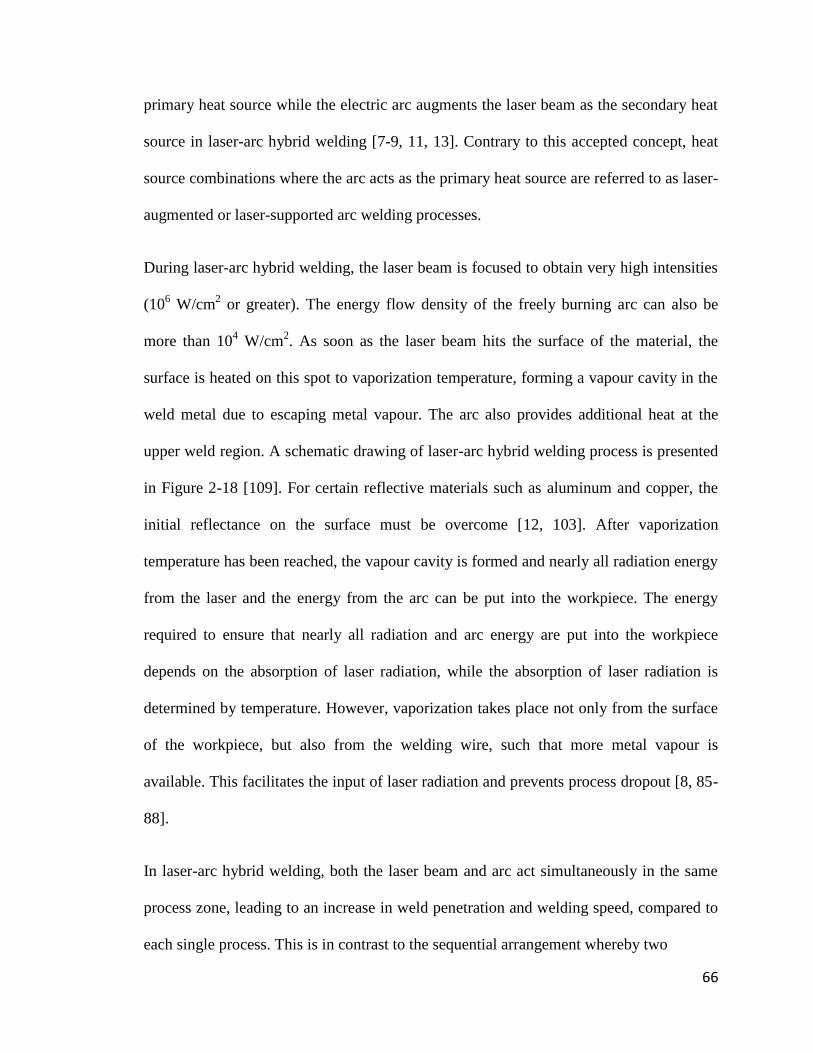
66
primary heat source while the electric arc augments the laser beam as the secondary heat
source in laser-arc hybrid welding [7-9, 11, 13]. Contrary to this accepted concept, heat
source combinations where the arc acts as the primary heat source are referred to as laser-
augmented or laser-supported arc welding processes.
During laser-arc hybrid welding, the laser beam is focused to obtain very high intensities
(106 W/cm
2 or greater). The energy flow density of the freely burning arc can also be
more than 104 W/cm
2. As soon as the laser beam hits the surface of the material, the
surface is heated on this spot to vaporization temperature, forming a vapour cavity in the
weld metal due to escaping metal vapour. The arc also provides additional heat at the
upper weld region. A schematic drawing of laser-arc hybrid welding process is presented
in Figure 2-18 [109]. For certain reflective materials such as aluminum and copper, the
initial reflectance on the surface must be overcome [12, 103]. After vaporization
temperature has been reached, the vapour cavity is formed and nearly all radiation energy
from the laser and the energy from the arc can be put into the workpiece. The energy
required to ensure that nearly all radiation and arc energy are put into the workpiece
depends on the absorption of laser radiation, while the absorption of laser radiation is
determined by temperature. However, vaporization takes place not only from the surface
of the workpiece, but also from the welding wire, such that more metal vapour is
available. This facilitates the input of laser radiation and prevents process dropout [8, 85-
88].
In laser-arc hybrid welding, both the laser beam and arc act simultaneously in the same
process zone, leading to an increase in weld penetration and welding speed, compared to
each single process. This is in contrast to the sequential arrangement whereby two

67
Figure 2 - 18: Schematic illustration of laser-arc hybrid welding
Source: Hybrid Laser-Arc Welding, Edited by Flemming Ove Olsen, Copyright 2009,
ISBN 978-1-84569-652-8. Reprinted with permission from Woodhead Publishing Limited
(14 May, 2013)

68
separate welding processes take place successively. The character of the overall process
may be determined either by the laser or the arc, depending on the ratio of the two power
inputs [103]. Laser-arc hybrid welding has several advantages over laser welding process
and arc welding process, and these are discussed next.
2.4.4 Advantages of Laser-Arc Hybrid Welding
Laser-arc hybrid welding integrates the best attributes of both laser welding and arc
welding processes, and has also addressed their limitations. The weld pool is usually
larger than laser welds and deeper than arc welds made with the same laser and arc
welding parameters [13]. The process is well-adapted to the welding of thick sections.
In comparison to laser welding, it has been reported that laser-arc hybrid welding is
characterized by higher process stability, higher bridgeability, increased welding speed,
deeper penetration, increased weldable material thickness, reduced cracking and porosity
susceptibility, and lower capital investment cost due to savings in laser energy [11, 13,
103]. Full penetration depths at gaps larger than 1mm was realized in a 6mm steel using a
2kW CO2 and 2.7kW MAG [116]. A very deep penetration of 16 mm was achieved in the
laser-MAG hybrid welding of pipeline steel by 10.5 kW laser power at a welding speed
of 1.2 m/min, without centerline pores or cracking as determined by X-ray testing [108].
An increase in welding speed by a combination of laser beam and arc, compared to laser
beam alone, during the joining of various materials has been reported [8]. For a 0.6mm
stainless steel, 50% increase in weld penetration was reported when a 400W CO2 laser
was combined with an arc in PALW (Plasma arc augmented laser welding) [117].
Porosity was reduced significantly in AA5083 aluminum alloy by combining 12kW CO2
laser with 3kW MAG [118]. A complete elimination of cracks and penetration of 6-8mm

69
were achieved in 10mm A6061 aluminum alloy by combining a 3.5kW Nd:YAG with a
TIG torch [119].
Compared to arc welding, the reported advantages of laser-arc hybrid welding include:
higher welding speed, lower heat input per unit length, lower residual stresses and
distortions, better mechanical properties, deeper penetration at higher welding speed,
narrower weld joint, greater process stability, and very smooth transition between weld
and base material [10, 15, 103, 104]. The ability of laser-arc hybrid welding to produce
deeper penetration weld has been demonstrated in Laser-TIG welding of a Magnesium
alloy [120]. It has been demonstrated that less total heat input is required to produce a
particular weld penetration in hybrid laser gas metal arc welding compared to GMAW
process alone, as shown in Figure 2-19 [121]. Steen [7], in his earlier experiment on the
effect of adding a laser to an electric arc on the arc current-voltage relationship using
mild steel, also demonstrated that an unstable arc can be stabilized by a laser beam.
Overall, the important advantages of laser-arc hybrid welding can be summarized as:
1. Increased welding speed
2. Increased weld penetration
3. Improved gap and misalignment tolerance
4. Enhanced process stability
5. Reduced cracking and porosity
6. Single pass welding of thick sections
7. Enhanced overall weld quality

70
Figure 2 - 19: Penetration depth at different heat input levels for CO2 laser, GMAW and
hybrid LAGMAW process
Source: C.V. Hyatt, K.H. Magee, J.F. Porter, V.E. Merchant and J.R. Matthews: Weld.
J., (2001) pp.163s-172s. Reprinted with permission from the American Welding Society
(2 August, 2013)

71
2.4.5 Parameters in Laser-Arc Hybrid Welding
In addition to welding parameters which are related to laser welding and arc welding as
individual processes, a number of parameters are also associated with laser-arc hybrid
welding. The parameters of laser-arc hybrid welding include [11, 113, 122, 123]:
Type of laser (Nd:YAG or CO2)
Type of arc (MIG-MAG, TIG or Plasma)
Relative positions of laser and arc
Laser power
Arc power (arc voltage and current)
Ordering of the process (laser or arc first?)
Laser focal point position
Angle (or inclination) of electrode
Shielding gas type
Shielding gas flow rate
Welding speed
Welding wire type
Welding wire diameter
Wire stick-out
Welding wire feed speed
Root opening tolerance
All these parameters influence the overall quality of the laser-arc hybrid welded joint. In
the next sub-section, some reported effects of welding parameters during laser-arc hybrid
welding of various materials are discussed.

72
2.4.6 Effect of Welding Parameters
Welding parameters play important roles in determining the characteristics and quality of
a welded joint. The depth of penetration during laser-arc hybrid welding has been
observed to be influenced by the distance between laser and arc, laser focal position,
welding speed and laser power. It has been suggested, based on reports in the literature
[11, 115, 118, 119, 123, 124-126], that an ideal relative distance between the laser and
arc is about 1-3mm. For example, the deepest weld penetration was obtained in a
stainless steel alloy when the distance between the sources was about 2-4 mm [122]. In
laser-arc hybrid welding in which a 1.8kW Nd:YAG laser was coupled with a TIG torch,
it was reported that the penetration was deeper and the bead width narrower for greater
relative distance between laser and arc (>2mm) when TIG beam is positioned before the
laser beam, but the penetration is deepest for a relative distance of 1-2 mm and shallower
at distances greater than 2mm when YAG laser beam is positioned before the TIG arc
(Figure 2-20 [125]). Positioning the arc point of interaction in the laser point of
interaction has been reported to result in reduced penetration [115]. In type 304 stainless
steel, it has been demonstrated that an increase in laser power produced an increase in
weld penetration depth [125].
Process ordering was also found to influence weld characteristics. It has been observed
that an increase in penetration of 10% could be obtained if a MAG source is placed after
the laser [118]. The laser focal point position in laser-arc hybrid welding is not usually
the same as that of pure laser due to the large curvature of the molten pool created by the
arc [11]. The choice of this focal point position depends on the type of laser, laser power,
arc power, and the material [116, 121, 125].

73
Figure 2 - 20: Influence of distance on penetration depths in laser-arc hybrid welding of
Type 304 SS
Source : Y. Naito, S. Katayama and A. Matsunawa: First International Symposium on
High-Power Laser Macroprocessing – Proceedings of SPIE, Vol. 4831 (2003) pp. 357.
Reprinted with permission from The International Society for Optical Engineering (23
May, 2013) and one of the Authors, Seiji Katayama (4 June, 2013).

74
The maximum welding speed possible for a particular laser power has been shown to
increase with increased arc current [127]. Increase in welding speed, in turn, has been
observed to reduce the depth of penetration [125, 127]. The depths of penetration
obtained during Nd:YAG/TIG hybrid welding process at different welding speeds is
presented in Figure 2-21 [125]. Porosity was also found to reduce with increasing arc
current, and was almost absent at 240A, for a YAG-MIG hybrid welding of type A5052
aluminum alloy [128]. An increased arc voltage has been also reported to result in an
increased bridgeability [122].
The type of shielding gas for laser-arc hybrid welding depends on the type of laser,
whether CO2 laser whereby plasma absorption takes place, or Nd:YAG laser where
plasma absorption is not a major concern [11]. Figure 2-22 [129] shows that under the
same conditions, the penetration depth of hybrid CO2 laser-TIG welded stainless steel
with low He content in the shielding gas is shallow, but the penetration depth increased
with increasing He content in the He-Ar mixture. It was observed that when the He
content is greater than 50%, the 3 mm stainless steel is fully penetrated. It has also been
reported that the penetration and geometry of weld beads depended on the volume of
oxygen in ambient air during laser-arc hybrid welding of steel with low S content [128].
The effect of the type and composition of filler materials on mechanical properties in
laser-arc hybrid welding of high strength steels has been also studied and reported [104].
2.4.7 Industrial Application of Laser-Arc Hybrid Welding
The laser-arc hybrid welding process is currently being used in production. It is making
an important impact in the medium and heavy section, as well as thin sheet, welding
industries [16, 17], with the goal of achieving a higher product quality while the

75
Figure 2 - 21: Influence of welding speed on penetration depth in laser-arc hybrid
welding of Type 304 SS
Source : Y. Naito, S. Katayama and A. Matsunawa: First International Symposium on
High-Power Laser Macroprocessing – Proceedings of SPIE, Vol. 4831 (2003) pp. 357.
Reprinted with permission from The International Society for Optical Engineering (23
May, 2013) and one of the Authors, Seiji Katayama (4 June, 2013).

76
Figure 2 - 22: Effect of He content in He-Ar shielding gas on penetration depth of CO2
laser-TIG hybrid welded 3 mm thickness 316L stainless steel plate.
Source: Hybrid Laser-Arc Welding, Edited by Flemming Ove Olsen, Copyright 2009,
ISBN 978-1-84569-652-8. Reprinted with permission from Woodhead Publishing Limited
(14 May, 2013)

77
performance is concurrently being improved. According to Pilarczyk et al [112], the first
industrial applications of laser-arc hybrid welding were car bodies made of aluminum
plates, using Nd:YAG/MIG, and steels, using laser CO2/MIG. It is also being claimed
that the first Laser/MIG-MAG hybrid welding system in serial operation was put in
operation by Fraunhofer ILT for welding oil tanks in year 2000 [130]. Some current
applications of laser-arc hybrid welding are discussed.
2.4.7.1 Automotive Applications
Leading global manufacturers that use laser-arc hybrid welding in automobile production
include Volkswagen, Daimler (maker of Mercedes Benz vehicles) and Audi [12, 131].
The motivations for these companies in adopting this joining technique include: high
weld quality and reliability, perfect fitting on the car body, light weight potential, good
metallurgical properties, and reduced cycle time. Higher gap bridging ability, in
comparison to laser welding alone, is another major advantage [11].
The strategy of Volkswagen is to have the highest amount of laser weldments in the
automotive industry [103]. One of Volkswagen‟s applications of laser-arc hybrid welding
is in manufacturing the Phaeton model (previously called Concept D1). All doors of this
car model are laser-arc hybrid welded. Volkswagen‟s requirement included a high degree
of stiffness in the door structure, which also required a good combination of sheet, cast,
and extruded materials. Aluminum was the preferred and used material (due to low
weight), and without laser-arc hybrid welding, use of big and heavy aluminum cast
materials would have been necessary. The Phaeton door consists of 7 gas metal arc, 11
laser, and 48 laser-arc hybrid weldments, making a 4980mm total length of welds on the
door [103]. The welds are mainly fillet seams on lap joints and butt seams.

78
For power train production at Daimler, an axle component type 204 from the Daimler
Chrysler C-Class was welded by laser-arc hybrid welding at 4.5 m/min speed and 9.0
m/mm wire feed rate [74]. Figure 2-23 [131] shows a laser hybrid welded axle
components at Daimler. Also, laser-arc hybrid welding is employed in joining the lateral
roof frame of Audi A8, which is equipped with various functional sheets [74]. Each
vehicle comprises of a total of 4.5 m of weld seams (Figure 2-24 [131]).
2.4.7.2 Shipbuilding and Railway Applications
Laser-arc hybrid welding has also found applications in shipbuilding and railway
industries. While the automobile industry is a high volume industry, the ship building
industry is characterized by several kilometers of welding in a single ship [11]. In 2001,
the shipyard Meyer Werft in Papenburg, Germany, invested in a technically ambitious
panel manufacturing line, which is equipped with a total of four high power (12 kW)
laser hybrid welding machines [132]. Butt welds were made from 20 m long and 4 m
wide steel plates to form deck panels, up to 20 m by 20 m. Figure 2-25 [132] shows the
first laser welded sandwich panels produced at Meyer Werft. By 2002, all flat sections for
the ships produced at Meyer Werft came from a new pre-manufacturing workshop where
laser hybrid welding had been integrated. It was estimated that the amount of laser hybrid
welds in a large cruise ship was approximately 50% of the total weld length, which may
be of the order of 400 km [132], the majority of the plates being in the order of 5 – 8 mm
in thickness.
Aker Yard, Finland builds cruise ships and ferries, and has three shipyards in Finland.
Aker Yard implemented laser hybrid welding, where a 6 kW fibre laser was integrated
into the existing panel production line in December 2006. This reduced the total cost of

79
Figure 2 - 23: An axle component from the Daimler C-Class.
Source: Hybrid Laser-Arc Welding, Edited by Flemming Ove Olsen, Copyright 2009,
ISBN 978-1-84569-652-8. Reprinted with permission from Woodhead Publishing Limited
(14 May, 2013)

80
Figure 2 - 24: Laser hybrid welding at Audi. The OEM applies the laser hybrid welding
process for 4.5 m of weld seams in the roof area of the new A8 and thus achieves higher
welding speeds and stronger seams.
Source: Hybrid Laser-Arc Welding, Edited by Flemming Ove Olsen, Copyright 2009,
ISBN 978-1-84569-652-8. Reprinted with permission from Woodhead Publishing Limited
(14 May, 2013)

81
Figure 2 - 25: The first laser welded sandwich panels produced at Meyer Werft,
Germany
Source: Hybrid Laser-Arc Welding, Edited by Flemming Ove Olsen, Copyright 2009,
ISBN 978-1-84569-652-8. Reprinted with permission from Woodhead Publishing Limited
(14 May, 2013)

82
investment. An overview of the installation and the various elements are provided in
Figure 2-26 [132]. Also, the Laser Fabricated Ship Structures program of the U.S. Office
of Naval Research developed a laser-arc hybrid welding technology for the production of
T-beams from high strength plates at high welding speeds with very low distortion [15].
The U.S. shipyard established a two-year payback threshold for economic justification of
capital purchases on laser-arc hybrid welding [15]. Many other shipbuilding companies
have adopted laser-arc hybrid welding in production. These include Blohm & Voss,
Fincantieri, Odense Steel Shipyards, amongst others [132].
In year 2000 Cloos Schweiβtechnik in Haiger, Germany, introduced a hybrid burner that
can be operated by a robot for railway applications [17]. This laser-arc hybrid
technology, developed by Cloos, is being used by Alstom Reichshoffen in Alsace,
France. The equipment consists of a laser-arc hybrid head with a rotating burner axle that
was built onto a welding robot and a seam monitor, with a laser sensor, which guarantees
the quality of the weld seams on the side walls of the train cars.
2.4.7.3 Other Applications
Aside from automobile, shipbuilding and railway applications, laser-arc hybrid welding is
used also in the construction of bridges, pipelines, earthmoving equipment, lifting
equipment and cranes [15, 111]. It is useful for joining components in transport,
petrochemical and mineral processing industries [18]. These components include pressure
vessels, autoclaves and container panels. In addition, laser hybrid welding technology has
been successfully applied in the joining of bicycle structures that are made of magnesium
alloys (Figure 2-27 [133]).

83
Figure 2 - 26: (a) An overview of installation, (b) the laser head and (c) the laser source
and MAG power supply for the laser hybrid welding set up at Aker Yard
Source: Hybrid Laser-Arc Welding, Edited by Flemming Ove Olsen, Copyright 2009,
ISBN 978-1-84569-652-8. Reprinted with permission from Woodhead Publishing Limited
(14 May, 2013)
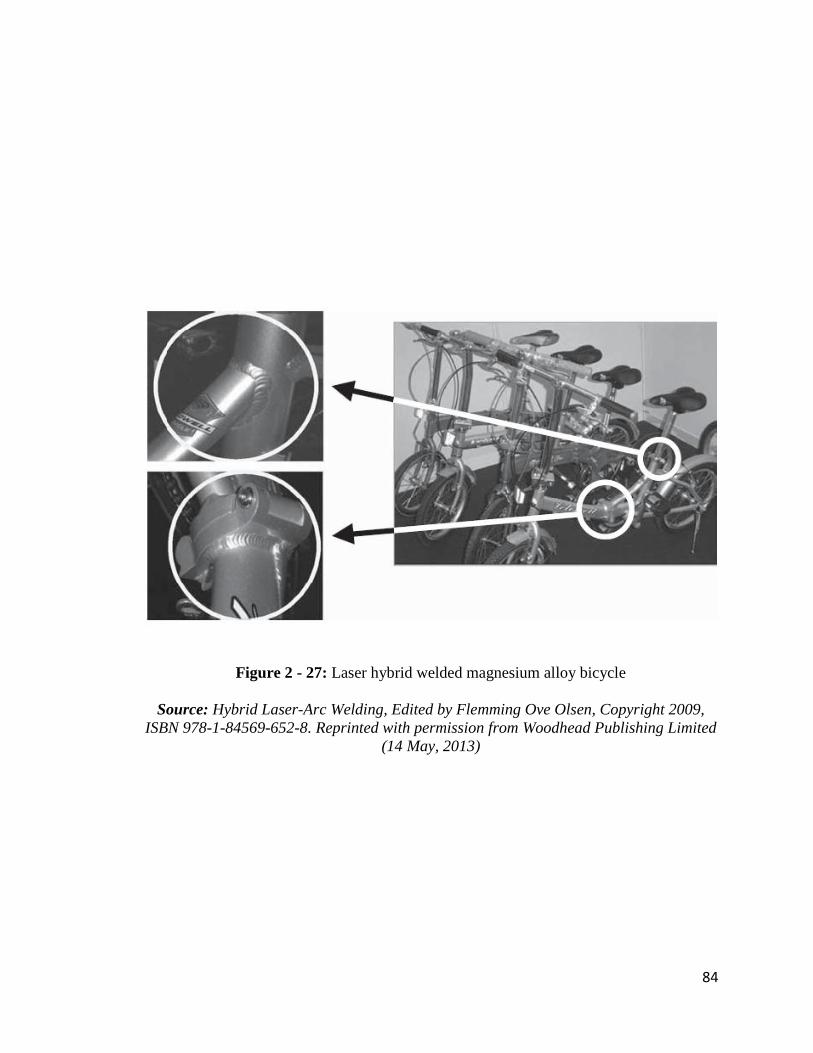
84
Figure 2 - 27: Laser hybrid welded magnesium alloy bicycle
Source: Hybrid Laser-Arc Welding, Edited by Flemming Ove Olsen, Copyright 2009,
ISBN 978-1-84569-652-8. Reprinted with permission from Woodhead Publishing Limited
(14 May, 2013)
85
Another important aspect of the application of laser-arc hybrid welding relates to the
types of materials that are currently being welded by the process. A review of previous
works revealed that the process has been applied to the joining of different iron based
materials including stainless steels [113, 122, 125, 128], mild steel [7, 127], high strength
steels [104, 113] and other types of steels [130, 134]. Laser-arc hybrid welding process
has also found wide a application in the welding of aluminum and aluminum alloys [112,
130, 135], which are particularly used in the manufacturing of automobile parts. Laser-
arc hybrid welding of various types of aluminum alloys has been reported. Although the
process has also been applied to the joining of magnesium alloys [120], titanium and tin
plates [8], very limited information exists about the joining of these materials using laser-
arc hybrid welding.
2.4.8 The Current State of Laser-Arc Hybrid Welding
In the previous sections the principle, benefits, parameters and applications of laser-arc
hybrid welding were reviewed. On the basis of this review, it is evident that laser-arc
hybrid welding, though useful in a wide range of industries, is only largely used in
applications where steels and aluminum alloys are the principal materials. Also, the
currently available information shows that a substantial amount of work is required in the
optimization of the welding process for steel and aluminum, especially considering the
fact that several combinations of the process parameters are possible. In addition to the
existence of several process parameters, different secondary heat sources can also be
combined with laser in a variety of process arrangements, depending on the specific
joining assignment [13]. Currently, most of the relevant welding parameters are
experimentally determined; confirming that process optimization for each material

86
requires a substantial level of practical experience [13]. It has been suggested that
expanding the application of laser-arc hybrid welding in the joining of important
materials will require considerable research, rigorous characterization and cost analysis
[10]. Some of the areas, which have not been given much attention, toward which
research effort on laser-arc hybrid welding is currently being tailored include: the
understanding of optimum welding parameters for various materials; study of
microstructural behavior of materials during welding; evaluation of weld properties.
Also, the correlation of pre-weld microstructural characteristics of materials with
materials weldability and the role of filler alloys of various compositions during laser-arc
hybrid welding are critical in the joining of crack-sensitive materials, such as nickel-base
superalloys. However, these have received less attention.
2.4.9 Scope and Objective of the Present Work
At present, there is limited data on the joining of superalloys by laser-arc hybrid welding.
The process is rarely applied to the joining of materials that are especially developed for
high temperature applications including rocket engines, and aero and land based gas
turbines. The fabrication of new turbine components and the repair of service damaged
components, such as turbine blades, discs and vanes, require highly efficient welding
processes. Laser welding and arc welding processes have been, and are still being, used
as individual joining processes for these applications. However, information on the
synergistic effect that can be produced by a combination of these processes in laser-arc
hybrid welding of turbine components is not yet available. As mentioned earlier, laser-arc
hybrid welding has been mainly applied to joining steels and aluminum alloys. This
process is yet to be commercially applied to several other materials such as nickel base

87
superalloys, cobalt-base superalloys and titanium alloys. This review of literature
suggests that there exist vast opportunities that are yet to be explored based on the current
state of laser-arc hybrid welding. However, the mere application of laser-arc hybrid
welding does not guarantee the elimination of the inherent weldability problem
encountered during fusion welding of precipitation strengthened nickel-base superalloys,
which is the heat-affected zone (HAZ) liquation cracking.
This research was initiated to perform a systematic and comprehensive study of the
cracking susceptibility of nickel-base IN 738 superalloy welds made by laser-arc hybrid
welding process, and how to minimize it by using a combination of
A. pre-weld microstructural modification through thermal treatment
B. the application of various welding filler alloys
The results of investigations performed to achieve this objective are presented in chapter
4 of this dissertation.

88
CHAPTER 3
MATERIALS AND EXPERIMENTAL PROCEDURE
3.1 Materials Preparation
Cast IN 738 LC (low carbon) was received in the form of plates having dimensions of
150 mm × 50 mm × 10 mm from PCC Airfoils, Ohio, USA. The chemical composition of
the as-received alloy in weight percent is listed in Table 3-1. Pairs of welding coupons of
dimensions approximately 75 mm x 20 mm x 5 mm were machined from the cast plates
by using a Hansvedt model DS-2 traveling wire electro-discharge machine (EDM). The
coupons were given the heat treatments listed in Table 3-2. The heat treatment designated
SHT is “solution heat treatment,” which is the generally used pre-weld heat treatment for
IN 738 superalloy. UMT (University of Manitoba heat treatment) and NUMT (New
University of Manitoba heat treatments) are pre-weld heat treatments developed by the
research group of Chaturvedi and Ojo to minimize cracking in IN 738 superalloy. Heat-
treated coupons were surface ground by using 120 grit size SiC papers to remove surface
oxides that formed on the coupons during heat treatment. The pairs of welding coupons
were butt-welded by laser-arc hybrid welding technique. Five different filler alloys,
namely IN 625, FM 92, IN 718, HY 282 and Rene 41 superalloys were used during
welding. The compositions of the filler alloys, which were received in the form wire
spools of 0.9 mm in diameter, are also included alongside the composition of the cast IN
738 base alloy in Table 3-1.
The laser-arc hybrid welds were sectioned transverse to the welding direction using the
Hansvedt model DS-2 traveling wire electro-discharge machine (EDM). 10 sections were
made from each of the butt welds. These were then prepared by standard metallographic
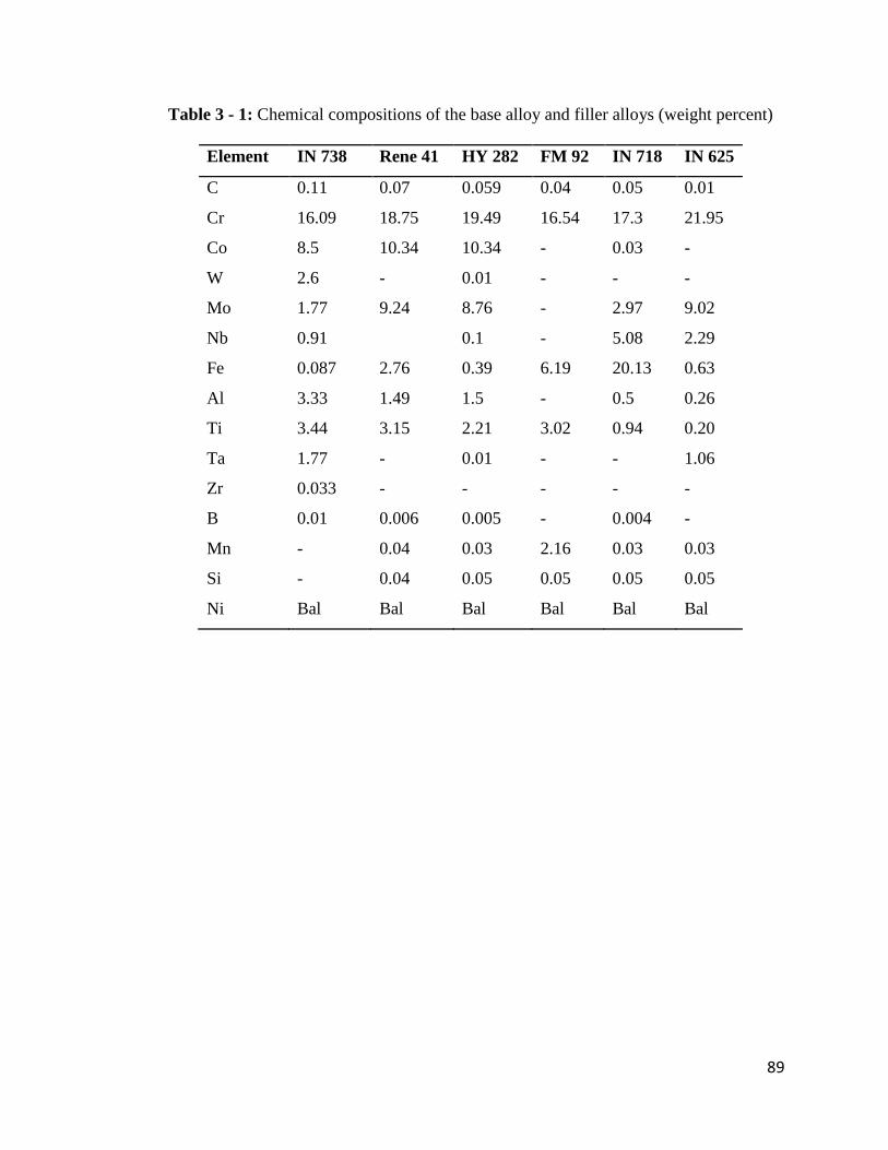
89
Table 3 - 1: Chemical compositions of the base alloy and filler alloys (weight percent)
Element IN 738 Rene 41 HY 282 FM 92 IN 718 IN 625
C 0.11 0.07 0.059 0.04 0.05 0.01
Cr 16.09 18.75 19.49 16.54 17.3 21.95
Co 8.5 10.34 10.34 - 0.03 -
W 2.6 - 0.01 - - -
Mo 1.77 9.24 8.76 - 2.97 9.02
Nb 0.91 0.1 - 5.08 2.29
Fe 0.087 2.76 0.39 6.19 20.13 0.63
Al 3.33 1.49 1.5 - 0.5 0.26
Ti 3.44 3.15 2.21 3.02 0.94 0.20
Ta 1.77 - 0.01 - - 1.06
Zr 0.033 - - - - -
B 0.01 0.006 0.005 - 0.004 -
Mn - 0.04 0.03 2.16 0.03 0.03
Si - 0.04 0.05 0.05 0.05 0.05
Ni Bal Bal Bal Bal Bal Bal

90
Table 3 - 2: A list of heat treatments used
Heat Treatments
1120oC / 2 h / AC (SHT)
1120oC / 2 h / AC + 1025oC / 16 h / WQ (UMT)
1120oC / 2 h / WQ + 1120oC / 24 h / FC (NUMT)
1120oC / 2 h / FC
1120oC / 4 h / FC
1120oC / 8 h / FC
1120oC / 12 h / FC
1120oC / 16 h / FC
1120oC / 24 h / FC
1025oC / 2 h / FC
1180oC / 2 h / FC
1120oC / 2 h / AC + 845oC / 24 h / AC (PWHT)*
AC = air-cooled, WQ = water-quenched, FC = furnace-cooled
*PWHT is the post-weld heat treatment

91
procedures for microstructural examination and etched electrolytically in 12 mL H3PO4 +
40 mL HNO3 + 48 mL H2SO4 solution at 6 volts for 5 seconds. Specimens selected for
electron backscattered diffraction (EBSD) -based analysis were chemo-mechanically
polished by using colloidal silica solution to a surface finish of about 0.05 μm prior to
analysis.
Cylindrical rods, 15 mm in length by 6 mm in diameter, for Gleeble simulation, were
machined from heat-treated plates using the wire EDM. The surfaces of these specimens
were also ground in order to remove surface oxides. Thermocouples were spot-welded on
each of these cylindrical specimens at the axial centre for temperature control and
measurement during Gleeble simulation. All simulated materials were sectioned in the
radial direction at the location of the thermocouples, using the wire EDM. These were
then prepared using standard metallographic techniques and electrolytically etched in 12
mL H3PO4 + 40 mL HNO3 + 48 mL H2SO4 solution at 6 volts for 5 seconds.
3 mm diameter discs of 100 μm thickness were machined from the weld zones of selected
welded coupons by the wire EDM for TEM analysis. The discs were dimpled and
polished to achieve a thickness of 10 μm and surface finish of about 0.05 μm at the centre
using a Gatan Model 656 Dimple Grinder. They were then ion-milled with Ar+ for about
4 hours in a Gatan Duomill Model 691 Precision Ion Polishing System equipped with a
liquid-nitrogen-cooled stage. Ion milling was started at 4.5 KeV (Ar+) at 7 degrees
glancing angle for 2 hours, and completed at 3 KeV (Ar+) at 3 degrees glancing angle
within another 2 hours.

92
3.2 Laser-Arc Hybrid Welding
Laser-Arc hybrid butt welding of the coupons was carried out by using a robotic fibre
laser-GMAW hybrid welding system at the Centre for Aerospace Technology and
Training (CATT), Standard Aero Limited, Winnipeg, Canada. The parameters used for
welding are listed in Table 3-3.
3.3 Gleeble Simulation
Gleeble simulation of the thermal cycling experienced by the HAZ during welding was
carried out by using a Gleeble 1500-D Thermo-Mechanical Simulation System.
Simulations were performed by rapidly heating the specimens at a heating rate of 150oC/s
to temperatures ranging from 1120oC to 1220
oC and held for different times ranging from
0.5 to 10 s, followed by air cooling.
3.4 Microscopy and Spectrometry (OM, SEM and EPMA)
The microstructures of the pre-weld, welded and Gleeble-simulated specimens were
examined and analyzed by a ZEISS Axiovert 25 inverted reflected-light optical
microscope (OM) equipped with a CLEMEX vision 3.0 image analyzer (Clemex
Technologies Inc., Longueuil, Canada), a JEOL JSM 5900 scanning electron microscope
(SEM) equipped with an Oxford (Oxford Instruments, Oxford, United Kingdom)
ultrathin window energy-dispersive spectrometer (EDS) and Inca analyzing software.
Further electron spectrometry of the weld fusion zone was carried out by using a
CAMECA SX 100 Electron Probe Microanalyzer (EPMA).
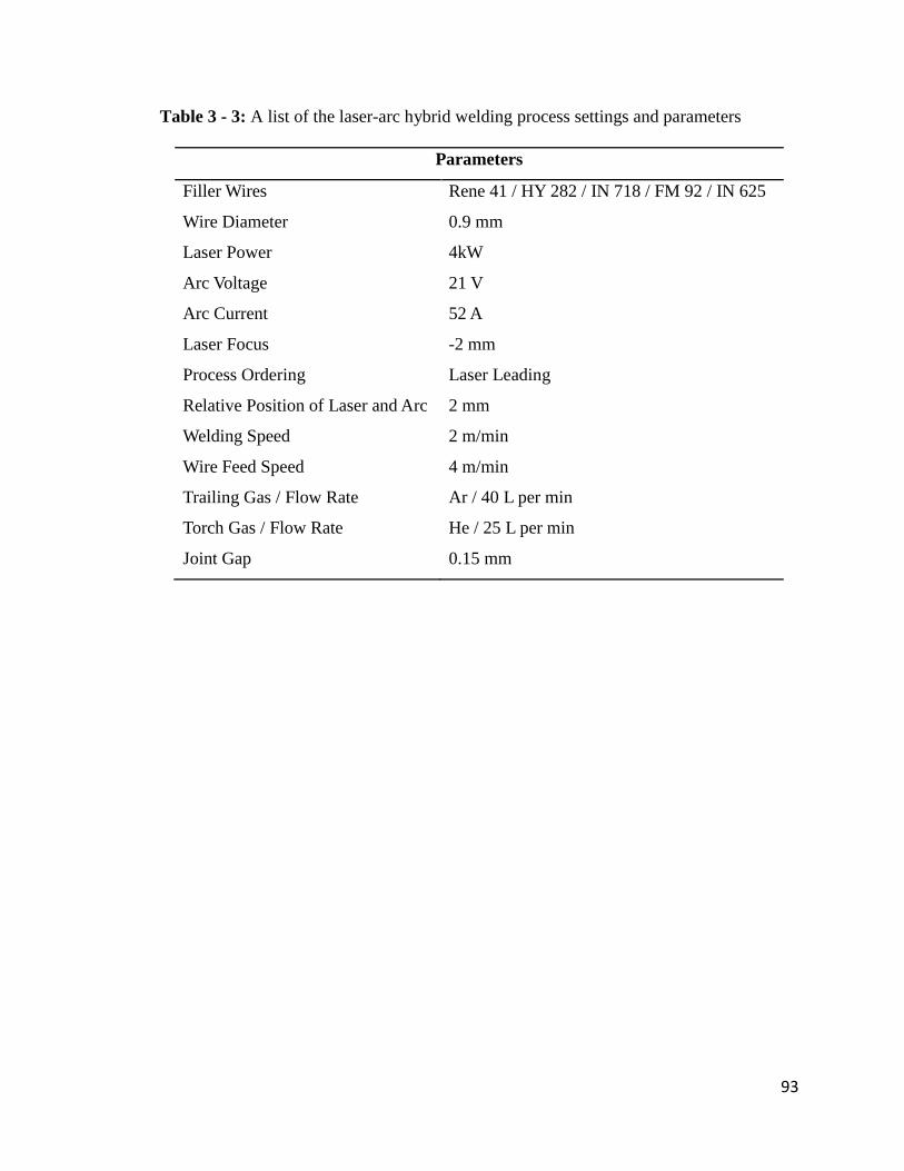
93
Table 3 - 3: A list of the laser-arc hybrid welding process settings and parameters
Parameters
Filler Wires Rene 41 / HY 282 / IN 718 / FM 92 / IN 625
Wire Diameter 0.9 mm
Laser Power 4kW
Arc Voltage 21 V
Arc Current 52 A
Laser Focus -2 mm
Process Ordering Laser Leading
Relative Position of Laser and Arc 2 mm
Welding Speed 2 m/min
Wire Feed Speed 4 m/min
Trailing Gas / Flow Rate Ar / 40 L per min
Torch Gas / Flow Rate He / 25 L per min
Joint Gap 0.15 mm

94
3.5 Transmission Electron Microscopy
TEM was carried out by using a JEOL 2100 field emission gun high resolution scanning
transmission electron microscope, equipped with an Oxford EDS, an electron energy loss
spectrometer and a high-resolution electron microscopy image simulation software. The
TEM was operated in both bright field and dark field modes. Electron energy loss
spectroscopy (EELS) and selected area diffraction pattern (SADP) analysis were carried
out on the TEM.
3.6 Electron Backscattered Diffraction (EBSD) Orientation Analysis
The grain structure of the fusion zone was studied by carrying out electron backscatter
diffraction (EBSD) -based orientation analysis using an HKL Nordlys EBSD detector
(developed by Oxford Instruments), which was attached to a Philips XL 30 Scanning
Electron Microscope. The EBSD detector was equipped with Oxford Instrument HKL
Technology Channel 5 suite of programs. Orientation mapping was carried out at a step
size of 1.5 μm. The projection of randomly selected points on inverse pole figures (IPFs)
was determined.
3.7 Thermodynamic Calculation
In order to study the solidification behaviour of the weld metal, theoretical temperature
step thermodynamic calculation was performed using JMatPro [136], the materials
property simulation package (developed by Sente Software Ltd., Surrey Technology
Centre, Guildford, United Kingdom). Calculation was performed at a step of 5oC for
temperatures decreasing from 1400oC to 800
oC

95
3.8 Hardness Measurement
The hardness of the fusion zone of weldments was measured with a Buehler
microhardness tester using a load of 300 g. The materials were polished to 1μm surface
finish before hardness testing.

96
CHAPTER 4
RESULTS AND DISCUSSION
A detailed result and discussion on the study performed on laser-arc hybrid welding of IN
738 superalloy is presented in this chapter. The chapter is divided into four major
sections. These are:
4.1. Microstructural Analysis of Laser-Arc Hybrid Welded Nickel-Base IN 738
Superalloy
4.2. Improvement in Laser-Arc Hybrid Weldability: The Development of a
Practicable and More Effective Pre-Weld Thermal Processing Procedure
4.3. The Role of Filler Alloy Composition on Laser-Arc Hybrid Weldability
4.4. Post-Weld heat Treatment (PWHT) Behaviour of the Laser-Arc Hybrid Welded
Material
4.1 Microstructural Analysis of Laser-Arc Hybrid Welded Nickel-Base IN 738
Superalloy
4.1.1 Introduction
In this section, the microstructural response of IN 738 superalloy to laser-arc hybrid
welding is discussed in details. The microstructures of the pre-weld heat treated materials
are discussed first, followed by fusion zone (FZ) microstructural characteristics. The
HAZ microstructure is also discussed and a major factor that needs to be addressed in
order to enhance the applicability of laser-arc hybrid welding for joining IN 738
superalloy is identified.

97
4.1.2 Microstructural Analysis of Pre-Weld Heat Treated Materials
Specimens of IN 738 superalloy were given SHT (1120oC/ 2h/ air-cool), UMT (1120
oC/
2h/ air-cool + 1025oC/ 16h/ water quench) and NUMT (1120
oC/ 2h/ water quench +
1120oC/ 24h/ / furnace cool) pre-weld heat treatments, as described in Section 3.1. SEM
micrographs of the pre-weld SHT IN 738 superalloy (Figure 4-1a) show a bimodal
distribution of the strengthening γ‟ precipitates, consisting of regular coarse primary γ‟
precipitates (with sizes ranging between 0.4 and 0.8 μm) and fine spherical secondary γ‟
precipitates (about 0.1 μm in diameter). MC carbides and γ-γ‟ eutectics, which usually
form during casting of the alloy, were found to persist during the SHT treatment (Figure
4-1a). In addition to MC carbides, Zr-rich particles were also observed in the pre-weld
material (Figures 4-1b, 4-1c and 4-1d). These Zr-rich particles, containing sulphur, have
been previously identified as M2SC sulphocarbides in IN 738 superalloy [26]. Further
analysis of the pre-weld SHT material revealed the presence of Mo-Cr-W-rich borides,
usually ahead of γ-γ‟ eutectics and along some grain boundaries in the interdendritic
regions of the alloy (Figures 4-1b, 4-1e and 4-1f). Hard refractory Mo-Cr-W-rich borides
formed as a result of boron segregation to grain boundaries during heat treatment and
casting, and were observed in several nickel-base superalloys [135, 137].
A SEM micrograph of the pre-weld UMT material is presented in the Figure 4-2,
showing a single-mode regular distribution of γ‟ phase with spherical shape and up to 0.8
μm in size. In addition to the spherical γ‟ precipitates, coarse γ‟ particles of larger size, up
to about 2 μm, were also distributed along some grain boundaries. MC carbides and γ-γ‟
eutectics that formed during casting were observed to have persisted in the alloy during
the solution heat treatment and aging of the UMT treated material. In addition to MC

98
a
γ-γ’ Eutectic
MC Carbide
Secondary γ’
Primary γ’
Mo-Cr-W-rich
boride
M2SC
b
c
f
d
e
Figure 4 - 1: Microstructure of the pre-weld SHT IN 738 material, showing (a) and (b)
secondary microconstituents, and SEM-EDS spectrum of (c) and (d) Zr-rich
sulphocarbide, (e) and (f) Mo-Cr-W-rich boride

99
MC
Carbide
γ-γ’ Eutectic
a
b
MC
Carbide
Coarse γ’
γ’ Precipitates
c
MC
Carbide
Figure 4 - 2: SEM micrographs of the pre-weld UMT-treated IN 738 superalloy,
showing (a) spherical γ‟ precipitates (b) MC carbides and γ-γ‟ eutectic (c) coarse γ‟
precipitates

100
carbides, Zr-rich M2SC sulphocarbides and borides were observed in the pre-weld UMT
material (Figure 4-3). The NUMT material consisted of irregularly shaped primary γ‟
precipitates of sizes up to 1.2 μm and very fine secondary γ‟ precipitates distributed in the
matrix γ phase (Figure 4-4). Coarse intergranular γ‟ precipitates, as well as MC carbides
and γ-γ‟ eutectics were observed in the NUMT material.
4.1.3 General Overview of Laser-Arc Hybrid Welded Material
A general overview of the weld microstructure in the SHT-treated material is presented in
the light-optical image of Figure 4-5a, showing two laser-arc hybrid butt-welded work
pieces and the weld bead profile. An optical micrograph of SHT IN 738 material, bead-
on-plate welded with fibre laser-beam using the same laser power, is also presented
(Figure 4-5b). These figures show that laser-arc hybrid welding produced a desirable
narrow weld profile in nickel-base IN 738 superalloy, similar to that usually obtained
during laser beam welding. Laser-arc hybrid welding exhibited keyhole profile, as
obtained in laser beam welding, and the penetration depth is strongly dependent on laser
power. It has been suggested that the weld pool produced by laser-arc hybrid welding is
wider than laser welds but deeper than arc welds made with the same laser and arc
parameters, respectively [10]. Addition of arc to laser was also found to increase weld
penetration for the same laser power [7-9]. This is consistent with observations in the
present work in that the laser-arc hybrid welds were deeper than the fibre laser welds
(Figure 4-5). In addition to the advantages of laser beam welding such as narrow welds,
higher welding speed and deeper weld penetration that can be realized in laser-arc hybrid
welding, it has also been reported that the combination of laser beam and arc results in

101
Mo-Cr-W-
Rich Particle
M2SC
Figure 4 - 3: SEM micrograph M2SC sulphocarbide and borides in the UMT-treated IN
738 superalloy

102
MC Carbide
Primary γ’
Secondary γ’
a
b
Figure 4 - 4: SEM micrographs showing various microconstituents in NUMT - treated
IN 738 superalloy

103
Work piece 1 Work piece 2
a
b
Figure 4 - 5: Light-optical images of weld profiles in SHT-treated IN 738 materials
welded with the same laser power of 4kW (a) the laser-arc hybrid weld (b) bead-on-plate
fibre laser weld. (Images are at the same magnification)

104
other advantages such as better gap bridgeability and better metallurgical properties due
to welding wire addition [112, 138].
A general assessment of the laser-arc hybrid welds produced in IN 738 superalloy in the
present work suggests that laser-arc hybrid welding has a great potential for improving
the weldability of nickel-base superalloys. Nevertheless, safety demands on aero gas
turbine components require the manufacturing of high quality welds during fabrication
and repair of components. Properties and performance of materials during service are
mainly controlled by the microstructure. Therefore, fusion zone (FZ) and heat-affected
zone (HAZ) microstructures in the laser-arc hybrid welded IN 738 superalloy were
studied and are discussed next.
4.1.4 Fusion Zone (FZ) Characteristics: Dendritic Microstructure, Elemental
Partitioning and Secondary Microconstituents
An optical micrograph of the FZ of the laser-arc hybrid welded SHT-treated IN 738
superalloy that was welded with IN 718 filler alloy, showing the columnar dendritic
microstructure of a region close to the fusion boundary, is presented in Figure 4-6. FZ
solidification cracking was not observed in the weld metal. Previous studies have shown
that higher cooling rates (shorter solidification time) in the FZ results in finer dendritic
microstructure [139]. The results of the present work showed that the secondary dendrite
arm spacing adjacent to the FZ boundary in the laser-arc hybrid welded IN 738
superalloy was 3.89 ± 0.41 μm. A relationship between the secondary dendrite arm
spacing, d, and the cooling rate in the FZ has been expressed as [140]
)14.......(....................nKRd

105
Figure 4 - 6: Light-optical image of the fusion zone
106
R is the cooling rate and K and n are constants, experimentally determined as 4.7 × 10⁻²
mm K1/3
S-1/3
and -0.4, respectively, for IN 738 superalloy [140]. Using this approach, the
cooling rate within the FZ of the laser-arc hybrid welded IN 738 superalloy was
estimated to be about 501oC/s. A similar estimation for a bead-on-plate fibre laser welded
IN 738 superalloy that was welded with the same laser power (4kW) showed that the
cooling rate within the FZ was about 813oC/s. The higher cooling rate and the relatively
finer FZ dendritic microstructure in the laser welds, compared to the laser-arc hybrid
welds, could be related to the amount of heat input during the two processes in that the
total power for the hybrid weld was about 5kW due to the addition of about 1kW arc
power. Nevertheless, the cooling rate of 501oC/s within the FZ of the laser-arc hybrid
welded IN 738 superalloy in the present work is significantly more rapid in comparison
to the solidification rates of conventional investment cast and directionally solidified
alloy ingots, which are usually below 5oC/s [141]. A high solidification rate, such as
experienced in the laser-arc hybrid weld, may be expected to lower the extent of
microsegregation of solutes in the FZ. However, the results of the present work indicates
that significant partitioning of various elements occurred between the dendrite core and
interdendritic region of the FZ of the laser-arc hybrid welded IN 738 superalloy during
welding, which is subsequently discussed.
The weld FZ has been considered as a small casting formed under special conditions
including an intensely stirred pool of liquid, high temperature gradients and rapid
solidification [142, 143]. The overall FZ microstructure is strongly dependent on the
partitioning of various elemental components in the weld metal during solidification. A
popular model, which has been used to describe solute redistribution during weld metal

107
solidification in fusion welded nickel-base superalloys and other materials, is the well-
known Scheil‟s equation, given by [144]
)24......(....................]1[ )1(k
sos fkCC
where Cs is the solute concentration in the solid at the solid-liquid interface, k is the
equilibrium partition coefficient, Co is the nominal solute concentration (which, in this
case, is the nominal concentration of the weld metal), and fs is the fraction of solid. Rapid
cooling rates during solidification of weld metal, such as those experienced in the present
work, could limit the extent of solute back-diffusion. Additionally, solid-state diffusion of
substitutional alloying elements in the solidified austenitic γ matrix can be considered
negligible under conditions typical of fusion welding [145]. These effects of negligible
solute back-diffusion and solid-state diffusion have been incorporated into Scheil‟s
equation as derived from Brody and Fleming‟s equation [146]. Therefore, this equation
can be conveniently used to estimate elemental partitioning coefficients in the weld
metal. The fraction of solid, fs is equal to zero under local equilibrium at the start of
solidification. If undercooling at the dendrite tip is also neglected, the first dendrite solid
that forms from the liquid will have a composition given by os kCC . Consequently, if
the dendrite core composition in the weld metal, Cs and the nominal composition of the
weld metal, Co are known, then the initial partition coefficients at the start of
solidification can be calculated. However, although Cs can be measured directly from the
dendrite core region of the FZ, another approach will be required to determine Co due to
material mixing that resulted from the addition of IN 718 welding filler wire with a
different nominal composition to the IN 738 base material in the weld metal.

108
Assuming a complete mixing of the base metal and the filler wire metal in the FZ and
given the welding speed and wire feed speed from the welding parameters, it is possible
to calculate the fraction of the total FZ volume that results from the consumption of the
filler wire. If SW and SF are the welding speed and the filler wire feed speed, respectively,
and LW and LF are the length of weld coupon traversed and the length of filler wire
consumed, respectively, at a certain time t during welding, then FFWW SLSLt ,
which gives WWFF SLSL . The total volume of filler wire, VF consumed during time t
can be expressed as
)34.....(....................2
2
W
WFFF
S
LSrLrV
r is the radius of the filler wire. Similarly, the total volume of the weld metal, VW at time
t can be expressed as
)44..(....................WW ALV
A is the cross-sectional area of the FZ measured in the plane transverse to the welding
direction. Therefore, the fraction of the total weld metal volume that results from the
consumption of the filler wire, can be calculated as
)54........(....................2
W
F
w
F
AS
Sr
V
VF
This fraction of the total weld metal volume and the nominal compositions of the base
metal (IN 738 superalloy) and the filler metal (IN 718 superalloy) were used to estimate
Co. The values of Cs, Co and k are presented in Table 4-1. The result showed that Ti, Ta,

109
Table 4 - 1: The measured values of Cs and the calculated values of Co and k
Ni Cr Al Ti Co Ta Nb Mo W Zr Fe
Co59.27 16.38 2.65 2.84 6.46 1.35 1.91 2.06 1.98 0.02 4.90
Cs56.63 16.48 2.50 2.05 6.35 0.93 1.24 1.95 2.01 0.01 5.43
k 0.96 1.01 0.94 0.72 0.98 0.69 0.65 0.95 1.02 0.50 1.11
k* 1.03 0.98 0.92 0.69 1.09 0.74 0.52 0.87 1.13 0.13 -
Note: k* are equilibrium partition coefficient values from the work of Ojo et al. [147] and
are included here for reference only.

110
Nb, Mo, Al and Zr, with k < 1 partitioned into interdendritic regions. Cr, Co and W with
k ≈ 1 were nearly evenly distributed between the dendrite core and the interdendritic
region, while Fe partitioned into the dendrite core. A similar microsegregation pattern has
been observed in the FZ of fusion welded IN 738 superalloy and other materials [143,
147-149]. Equilibrium partition coefficient values from the work of Ojo et al. on GTA
welded IN 738 superalloy [147] are also included in Table 4-1 for reference purposes.
It should be noted that no attempt was made to determine the values of k for C and B due
to the difficulty in quantifying low atomic number elements with sufficient accuracy.
Also, extremely large acquisition times would be required to obtain statistically
acceptable X-ray counts as a result of low nominal concentrations of these elements in
the weld metal and small X-ray yield due to their low atomic number values.
Nevertheless, it is important to discuss the partitioning behaviour of these elements due to
the significant role they play in the formation of secondary microconstituents during
solidification. The partition coefficient of C in alloys similar to IN 625 was determined to
be approximately 0.2 [150]. Auger electron spectroscopy has also been used to
experimentally confirm the partitioning of C into the interdendritic region [151].
Additionally, binary Ni-X phase diagrams suggests k < 1 for C and B in nickel [152].
Therefore, it is reasonable to assume that C and B partitioned into the interdendritic
region during solidification of the weld metal in the present work. It should also be noted
that, while partition coefficients are not necessarily constant during the entire
solidification process, they are very useful in explaining the formation of secondary
microconstituents in the interdendritic regions of the weld metal.

111
An SEM micrograph of the weld FZ microstructure in the laser-arc hybrid welded IN 738
superalloy is presented in Figure 4-7a, showing the nickel-base γ matrix phase and
secondary solidification microconstituents. A higher magnification SEM image of the FZ
revealed the presence of sub-micron size particles in the interdendritic regions (Figure 4-
7b). SEM-EDS line scan across the interdendritic regions containing these particles
(Figure 4-8) showed, qualitatively, the partitioning of C, Ti, Nb and Mo, which are
known to be carbide formers in nickel-base superalloys, into the interdendritic regions.
The significantly small size of these particles precludes their accurate quantitative
analysis by either SEM-EDS or EPMA-WDS techniques due to the limitation imposed by
the larger electron beam probe size and the resultant signal contributions from matrix
elements. Therefore TEM analysis of these FZ particles was carried out. Figure 4-9a
shows a bright field TEM image of an interdendritic particle, having a size of about 300
nm. Electron energy loss spectroscopy (EELS) spectrum in Figure 4-9b and selected area
diffraction pattern (SADP), presented in Figures 4-9c, show that the particle is an MC-
type carbide with a face-centred cubic (fcc) crystal structure and a lattice parameter of
0.446nm.
4.1.5 Fusion Zone (FZ) Characteristics: Grain Structure
It is generally known that the grain structure of the FZ can significantly affect its
susceptibility to solidification cracking during welding [53]. In a system where nucleation
of a grain occurs from a liquid which is in contact with a flat substrate, the energy barrier
for the grain to nucleate on the substrate is given by [153]
)64......(..........).........32()(3
4 3
2
23
CosCosTH
TG
m
mLG

112
a
b
Figure 4 - 7: SEM images of the fusion zone of the laser-arc hybrid welded material that
was SHT-treated

113
C-Kα1,2
Ti-Kα1
Nb-Lα1
Mo-Lα1
Figure 4 - 8: SEM-EDS line scan across the interdendritic regions in the fusion zone

114
[123]
111
420
331
(c)
(a)200 nm
C-K
Ti-L2,3
Nb-M3
Inte
nsi
ty
Electron Energy Loss (eV)(b)
Figure 4 - 9: (a) TEM bright field image of MC-type carbide (b) EELS spectrum of the
carbide (c) TEM-SADP

115
Tm is the equilibrium melting temperature, ΔHm is the latent heat of melting, ΔT is the
undercooling below Tm, θ is the contact angle. The geometry of the process is
schematically presented (Figure 4-10), where the parameters γLG, γLS and γGS are the
surface energies of the liquid-grain, liquid-substrate and grain-substrate interfaces,
respectively. A complete wetting of the substrate by the liquid would result in zero
contact angle (θ = 0) and zero energy barrier (ΔG = 0). During weld cooling, the base
material at the fusion boundary acts as the substrate for nucleation. Complete wetting of
the base material usually occurs, such that θ = 0 and new grains nucleate easily from the
liquid in contact with the substrate. If the base material and the material of the weld metal
are structurally similar, atoms from the liquid can be arranged on the base material grains
without any alteration in the crystallographic orientation of the substrate. Such an
epitaxial nucleation results in grains with the same orientations in the base metal and the
weld metal at the fusion boundary. The continuity of crystallographic orientation across
fusion boundaries has been observed in some alloy systems [53, 154-156].
In the present work, epitaxial nucleation and growth of grains is expected to dominate the
grain structure at the fusion boundary, since the crystal structure of the base material and
the weld metal are the same and the condition for epitaxial nucleation of grains (θ = 0) is
fulfilled. Electron back-scattered diffraction (EBSD) - based crystallographic orientation
analysis showed that grain formation at the fusion boundary was not completely
characterized by epitaxial nucleation and growth, as expected. Figure 4-11a shows a SEM
image of a fusion boundary in the laser-arc hybrid welded SHT-treated IN 738 superalloy
with an inset whose EBSD-based grain map is presented in Figure 4-11b.
Crystallographic orientation relationship between randomly selected points in the base

116
LIQUID
SUBSTRATE
GRAIN
θ
γLG
γLS γGS
Figure 4 - 10: Schematic illustration of nucleation of a grain on a planar substrate from a
liquid

117
b
c
1
6
3
4
2
5
FZ
HAZ
FZ
HAZ
X0
Y0
a
Figure 4 - 11: EBSD-based data, showing (a) forescatter SEM image of the fusion
boundary, (b) a map of grains in random colours for the inset at the fusion boundary and
(c) the projection of points 1-6 on inverse pole figures.

118
metal and the FZ was analysed by using stereographic projection of the inverse pole
figures (IPF) along X0, Y0 and Z0 directions (Figure 4-11c). Here X0 and Y0 are
orthogonal in the plane of the figure, as shown in Figure 4-11a, and Z0 is the direction
perpendicular to the plane of the figure. Points 1, 2 and 5 are in the HAZ while points 3, 4
and 6 are in the FZ. Points 1 and 2 are in the same grain in the HAZ and point 5 is in
another grain in the HAZ. Figures 4-11a and 4-11b show that the grains at points 3, 4 and
6 of the fusion zone have grown epitaxially on the grains of the HAZ. This is confirmed
by Figure 4-11c which shows that points 1 and 2 (in the same grain in the HAZ) have
approximately the same projection on the IPF as points 3 and 4 of the FZ for all the three
directions X0, Y0 and Z0. Similarly, points 5 and 6 have the same projection on the IPF.
The result also revealed that while some epitaxial nucleation of grains occurred at the
fusion boundary, a significant number of grains nucleated at the boundary without any
orientation relationship with the HAZ. In fact, grains that formed far away from the
fusion boundary, especially at the weld centre in the upper weld region appeared
equiaxed and without any orientation relationship with grains in the base metal (Figure 4-
12). It has been suggested that, in principle, liquid convection in the weld pool can result
in fragmentation of the dendrite tips in the mushy zone, which are then carried into the
bulk weld pool [53]. The fragmented dendrites can act as nuclei for new grains if they are
able to survive the temperature of the bulk weld pool, resulting in heterogeneous
nucleation and growth of grains.
Additionally, some coarse MC carbides with sizes similar to the MC-type carbides of the
base metal were also observed in the FZ (Figure 4-13). It is that either the particles were
present in the pre-weld alloy but did not dissolve completely in the weld pool during

119
a
b
FZ
HAZ
FZ
HAZ
Equiaxed
Grains
Figure 4 - 12: EBSD-based data, showing (a) low magnification forescatter SEM image
of the fusion zone, (b) a map of grains in random colours for the inset in a.

120
Coarse MC Carbide
Figure 4 - 13: SEM image showing coarse MC carbide in the fusion zone

121
welding or the particles nucleated and grew from the weld pool prior to nucleation of the
γ dendrite. Nevertheless, Differential Thermal Analysis (DTA) was used to establish that
the solidification sequence of IN 738 superalloy starts by nucleation and growth of γ
dendrite rather than MC carbides. It was reported that some primary MC-type carbides
can be stable and remain in the melt above the liquidus temperature of the alloy, up to
1550oC, for 5 - 10 minutes [157]. The primary MC carbides that persisted in the weld
pool during solidification can also act as nucleation sites for new grains in the FZ. Also,
fine equiaxed grains, such as observed at the upper weld centre region in Figure 4-12, are
suggested to be often less susceptible to solidification cracking than coarse columnar
grains [61]. Formation of fine equiaxed grains at the weld centre could have contributed
to the absence of FZ centreline cracking in the alloy.
4.1.6 Microstructural Analysis of the Heat-Affected Zone (HAZ)
SEM microstructural analysis of the HAZ revealed the occurrence of intergranular cracks
of varying sizes, up to about 350 – 400 μm, adjacent to the fusion zone. Figure 4-14a
shows a typical crack in the HAZ. While no cracks occurred exclusively in the fusion
zone, the cracks that originated at the grain boundaries in the HAZ extended,
occasionally, into the fusion zone. Higher magnification SEM examination revealed the
occurrence of cracks ahead of liquid film migration (LFM) at the grain boundaries,
suggesting that intergranular liquation preceded cracking at these boundaries as shown in
Figure 4-14b. Also, re-solidified products formed along the crack paths (Figures 4-14b
and 4-15), which is a common characteristic of liquation cracking. The occurrence of
HAZ intergranular liquation cracking usually requires the formation of a continuous

122
Resolidified
Products
Fusion
Zone
HAZ
Cracks
a
b
Figure 4 - 14: SEM micrographs of the laser-arc hybrid welded SHT-treated IN 738
material, showing (a) a typical HAZ crack (b) liquid film migration (LFM) and re-
solidified products along a crack path

123
5 μm
Liquated γ’
a
b
Figure 4 - 15: SEM micrographs showing the morphology of crack paths and delineation
of crack paths by re-solidified products in the laser-arc hybrid welded UMT-treated IN
738 material

124
intergranular liquid film and the stability of the intergranular liquid film to temperatures
at which thermally generated tensile stresses are sufficient to cause cracking during weld
cooling [69]. A known mechanism by which intergranular liquation occurs in the HAZ
during welding is constitutional liquation of various phases. Constitutional liquation was
suggesting that intergranular liquation preceded cracking at these boundaries as shown in
Figure 4-14b. Also, re-solidified products formed along the crack paths (Figures 4-14b
and 4-15), which is a common characteristic of liquation cracking. The occurrence of
HAZ intergranular liquation cracking usually requires the formation of a continuous
intergranular liquid film and the stability of the intergranular liquid film to temperatures
at which thermally generated tensile stresses are sufficient to cause cracking during weld
cooling [69]. A known mechanism by which intergranular liquation occurs in the HAZ
during welding is constitutional liquation of various phases. Constitutional liquation was
first proposed by Pepe and Savage, when they observed liquation of titanium sulphide
particles in 18-Ni maraging steel [64]. This phenomenon has been subsequently observed
and used to explain non-equilibrium sub-solidus melting of second phases in various
alloy systems during welding [65, 66, 68, 147]. In the present work, constitutional
liquation of the strengthening γ‟ phase, γ-γ‟ eutectic, MC Carbides and other phases was
observed to have contributed to intergranular liquation in the HAZ.
4.1.6.1 Constitutional Liquation of γ’ precipitates and γ-γ’ eutectic
Rapid heating of an alloy containing intermetallic particles to temperatures equal to or
above the eutectic transformation temperature could result in constitutional liquation of
the intermetallic particles if they survive to the eutectic temperature during heating. The
γ-γ‟ eutectic transformation in IN 738 superalloy occurs over a range of temperatures,

125
which could be below 1180oC, the γ‟ solvus temperature in IN738 superalloy [45]. The
persistence of γ‟ precipitates to temperatures above their equilibrium solvus temperature,
up to γ-γ‟ eutectic transformation temperature could result in their dissolution by
constitutional liquation. SEM microstructural examination of γ‟ precipitates in the HAZ
of the laser-arc hybrid welded IN 738 superalloy revealed that the particles dissolved
essentially by constitutional liquation during welding (Figure 4-16a). Constitutional
liquation of γ‟ precipitate was observed to have contributed to intergranular liquation in
the HAZ (Figure 4-16b). Additionally, SEM analysis of the HAZ revealed the liquation
of γ-γ‟ eutectics (Figure 4-16c), with microcracks observed in the vicinity of the liquated
eutectics.
In order to study and understand the effect of the rapid thermal cycling experienced by
the alloy in the HAZ during welding, Gleeble simulation of HAZ microstructure was
performed. The results of the simulation performed at temperatures below the equilibrium
solidus of the alloy (usually around 1234oC [158]) revealed significant sub-solidus
liquation of various phases in the alloy. For example, the SEM micrograph of Figure 4-
17a shows re-solidified fine γ-γ‟ eutectic microconstituents that formed as a result of
liquation and subsequent resolidification of intergranular γ‟ precipitates in a Gleeble
specimen that was rapidly heated to 1180oC. Figure 4-17b also shows the liquation of γ-
γ‟ eutectics and re-solidified products ahead of the liquated eutectics in the Gleeble-
simulated material. The contribution of γ‟ precipitates liquation to HAZ intergranular
liquation in IN 738 superalloy has been reported to be one of the major factors
influencing HAZ intergranular cracking in the alloy [147].

126
a
b
c
Cracks
Liquating γ-γ’
eutectic
Liquating γ’
Precipitates
Figure 4 - 16: SEM micrographs of the welded SHT-treated IN 738 material showing (a)
constitutional liquation of γ‟ precipitates in the HAZ (b) the contribution of constitutional
liquation of γ‟ precipitates to intergranular liquation (c) liquation of γ-γ‟ eutectic
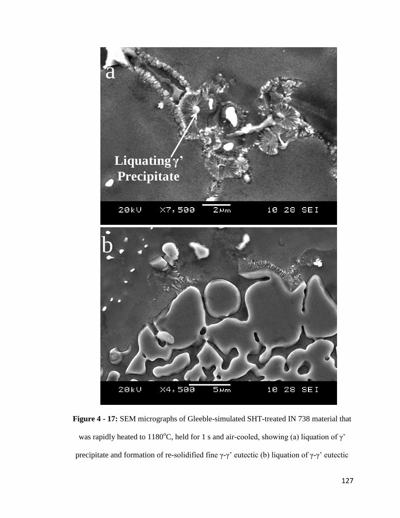
127
a
b
Liquating γ’
Precipitate
Figure 4 - 17: SEM micrographs of Gleeble-simulated SHT-treated IN 738 material that
was rapidly heated to 1180oC, held for 1 s and air-cooled, showing (a) liquation of γ‟
precipitate and formation of re-solidified fine γ-γ‟ eutectic (b) liquation of γ-γ‟ eutectic

128
4.1.6.2 Liquation of MC Carbides and Other Phases
Apart from constitutional liquation of γ‟ precipitates, SEM examination of the HAZ
showed the delineation of intergranular crack paths by re-solidified products that were
found to be rich in carbide-forming elements, Ti, Ta and Nb (Figure 4-18a and 4-18b),
suggesting that the liquation of MC carbides and M2SC sulphocarbides could have
contributed to intergranular liquation in the HAZ. The results of Gleeble simulation in the
present work showed sub-solidus liquation of M2SC sulphocarbides and MC carbides
(Figure 4-19a and 4-19b). The presence of sulphocarbides has been shown to be
detrimental to tensile ductility of nickel-base superalloys [159]. In addition to carbides
liquation, there were indications that borides could have also decomposed during the
welding thermal cycling. Figure 4-19c is a SEM micrograph of the Gleeble material that
was rapidly heated to 1180oC, showing re-solidified products that apparently formed
from the decomposition of borides. SEM-EDS line scan across the re-solidified products
showed the enrichment of this region in boride- and carbide-forming elements, namely,
Mo, Cr, W, Nb, Zr and B (Figure 4-20). It has been suggested that an abrupt
decomposition of M2SC and boride particles during welding could cause the release of S
and B atoms, which are known to be melting point depressants in nickel-base alloys
[147]. The release of melting point depressants by particle decomposition and their
segregation to intergranular regions during welding would lower the melting temperature
of the grain boundaries. This would then contribute significantly to non-equilibrium
intergranular liquation and susceptibility to HAZ intergranular cracking.
The results of the present microstructural study showed that while FZ cracking may not
be a problem during laser-arc hybrid welding of IN 738 superalloy, intergranular

129
Ti-Ta-Nb-rich
product
Figure 4 - 18: SEM micrographs and SEM-EDS spectrum showing products rich in
carbide forming elements along a crack path in the welded SHT-treated material

130
M2SC
Sulphocarbide
MC Carbide
Liquating γ-γ’
eutectic
a
b
c Resolidified
products
Figure 4 - 19: SEM micrographs of Gleeble-simulated SHT-treated IN 738 materials that
was rapidly heated to 1180oC, held for 1 s and air-cooled, showing (a) liquation of M2SC
sulphocarbide (b) liquation of MC carbide and (c) re-solidified products rich in boride
forming elements

131
B-Kα1,2
Cr-Kα1
Zr-Lα1 Nb-Lα1
Mo-Lα1
W-Mα1
Figure 4 - 20: SEM-EDS line scan across re-solidified products in a SHT-treated Gleeble
material that was rapidly heated to 1180oC, held for 1 s and air-cooled

132
liquation, caused by the liquation of various phases, and the resultant HAZ cracking are
important factors to be considered in the application of this welding technology in the
joining of the superalloy. Although laser-arc hybrid welding appears promising for
improving the weldability of nickel-base IN 738 superalloy, a suitable weldability
improvement procedure is required in order to significantly minimize or totally eliminate
HAZ cracking in the alloy. Possible weldability improvement strategies could include
modification of the pre-weld microstructure and improvements in the selection of process
parameters, which are considered critical for realizing the benefits of laser-arc hybrid
welding.

133
4.2 Improvement in Laser-Arc Hybrid Weldability: The Development of a
Practicable and More Effective Pre-Weld Thermal Processing Procedure
4.2.1 Introduction
In this section, the results of weldability studies performed on laser-arc hybrid welded IN
738 superalloy specimens that were subjected to various pre-weld thermal treatments are
discussed. The need for developing a more industrially feasible heat treatment was
identified. A major finding in this work, which was the development of a more
industrially feasible pre-weld thermal processing of the alloy, is presented. The newly
developed thermal treatment procedure is found to be both practicable and effective in
drastically reducing HAZ intergranular cracking in IN 738 superalloy.
4.2.2 Assessment of Laser-Arc Hybrid Weldability of IN 738 Superalloy Specimens
Subjected to Various Pre-Weld Thermal Processing
In the last section, HAZ intergranular liquation cracking was identified as a major
limiting factor that needs to be properly addressed in the application of laser-arc hybrid
welding for the joining of nickel-base IN 738 superalloy. HAZ intergranular liquation
cracking is common to fusion welding processes. Previous studies have shown that pre-
weld thermal processing of materials, hence, pre-weld microstructure, is critical in
determining the susceptibility of precipitation strengthened nickel-base superalloys to
HAZ intergranular cracking [160]. At present, the thermal treatment usually applied to IN
738 superalloy is the widely known standard solution heat treatment (SHT), which has
been assessed to result in a highly crack susceptible pre-weld microstructure in the alloy
[158, 161]. A thermal treatment procedure designated as UMT was found to significantly
reduce HAZ intergranular liquation cracking in IN 738 superalloy during TIG welding [3,

134
158], which is an arc welding process. A better improvement in HAZ cracking resistance
of the alloy was achieved during CO2 laser beam welding by the application of another
pre-weld heat treatment, NUMT. Laser-arc hybrid welding involves a combination of the
two major welding technologies, namely, arc welding and laser welding. In the present
work, a systematic study was performed to understand the microstructural response and
cracking resistance of IN 738 superalloy subjected to SHT, UMT and NUMT treatments
prior to laser-arc hybrid welding, which is discussed next.
Figure 4-21 shows the total crack lengths measured in 10 sections each of the welded
materials. It was observed that HAZ intergranular cracking was highest in the SHT
material, followed by the UMT material. The least total crack length was realized in the
material that was subjected to the NUMT treatment. The reason for excessively high
cracking susceptibility in SHT-treated IN 738 superalloy has been previously attributed
to significant intergranular liquation in the HAZ, as was also discussed in the last section,
and the inability of the base alloy to accommodate welding stress due to high hardness [3,
161]. The excessively high cracking susceptibility of the SHT material in this work is
consistent with the previous findings. Although the UMT and NUMT materials showed
notable improvements over the SHT material, the results revealed that the extent of
cracking in the NUMT material was significantly lower than that observed in the UMT
material. Therefore understanding the factors responsible for the better performance of
the NUMT over UMT was considered crucial and potentially useful for developing a
more effective heat treatment for the alloy. HAZ intergranular liquation cracking usually
results from a competition between the formation of a continuous intergranular liquid and
the development of on-cooling tensile stresses in the HAZ regions. Expansion and

135
0
1000
2000
3000
4000
5000
6000
7000
SHT UMT NUMT
Total crack length in Laser-Arc Hybrid Welds
Tota
l Cra
ck L
en
gth
(μ
m)
Heat Treatment
Figure 4 - 21: Total crack lengths in 10 sections each of IN 738 materials subjected to
SHT, UMT and NUMT.

136
contraction occurs in the material when the temperature changes during welding. This is
due to the temperature dependence of the elastic modulus and yield strength of the
material [55]. Contraction during weld cooling usually results in the generation of on-
cooling tensile stresses [52, 56, 162]. The mechanical driving force for cracking, which is
the on-cooling tensile stress, is usually present during welding. Therefore, it is
conceivable that reduction in the ductility of the material by the formation of continuous
intergranular liquid is the major factor determining susceptibility to HAZ intergranular
liquation cracking. In order to investigate the resistance of the NUMT material to HAZ
cracking, a Gleeble simulation experiment was performed to evaluate intergranular
liquation behaviour in the UMT and NUMT materials.
UMT and NUMT materials were rapidly heated to temperatures ranging from 1120oC to
1220oC at 150
oC/s, held for 1 s and air-cooled. A significant extent of liquation,
characterized by the decomposition of borides, was first observed in the UMT material at
1150oC. Re-solidified fine γ-γ‟ eutectic products formed in the vicinity of the
decomposed borides in the UMT sample at 1150oC. Borides decomposition contributed
substantially to intergranular liquation in the UMT sample and significant liquation of γ‟
and γ-γ‟ eutectic occurred at all temperatures from 1150oC to 1220
oC. Figure 4-22 shows
some selected SEM micrographs of Gleeble-simulated UMT samples at various
temperatures from 1150oC to 1220
oC. Contrary to the liquation behaviour observed in the
UMT material, no significant intergranular liquation was noticed at temperatures up to
1180oC in the NUMT material that did not contain any boride phases. Although γ‟
precipitates appeared to have liquated below 1180oC, the contribution of the liquation of
γ‟ precipitates to intergranular liquation in the NUMT material was not noticeable until

137
Boride
Boride
LFM
Liquated MC
Carbide
1150oC 1160oC
1180oC 1180oC
1200oC 1220oC
Figure 4 - 22: Selected SEM micrographs of UMT materials that were Gleeble-simulated
at various temperatures.

138
around 1180oC to 1200
oC (Figure 4-23). The results of this Gleeble simulation showed
that intergranular liquation starts at a lower temperature in the UMT material compared
to the NUMT material. This finding suggests that the temperature range over which non-
equilibrium HAZ intergranular liquation occurs is larger in the UMT material compared
to the NUMT material. The occurrence of significant intergranular liquation in the UMT
material at lower temperatures was observed to be in close association with the
decomposition of borides in the material. The decomposition of boride particles in the
interdendritic regions of the UMT material, and more importantly at the grain boundaries,
would have resulted in the release of elemental boron into these grain boundaries, thereby
lowering their effective melting temperature. Therefore, the effectiveness of NUMT in
reducing HAZ intergranular liquation cracking during welding can be related to its better
resistance to intergranular liquation, especially at lower temperatures, compared to the
UMT that exhibits significant liquation over a larger temperature range.
As discussed earlier, the pre-weld thermal treatment that is usually applied to IN 738
superalloy is the SHT, despite its excessively high susceptibility to HAZ intergranular
cracking. Although UMT and NUMT showed better performance than SHT and the
NUMT‟s performance is especially desirable, these heat treatments are not industrially
applicable. The non-applicability of UMT and NUMT results from their requirement for
water quenching (Table 3-2) as a process step during heat treatment, which is usually
difficult to achieve in the aerospace industry where most of the thermal processing are
performed under vacuum conditions. In order to improve the weldability of IN 738
superalloy during laser arc hybrid welding, it was necessary to develop another pre-weld
thermal treatment procedure that is effective in minimizing or totally eliminating HAZ

139
Grain
Boundary
Grain
Boundary
1180oC
1180oC1170oC
1200oC
Figure 4 - 23: Selected SEM micrographs of NUMT materials that were Gleeble-
simulated at various temperatures.

140
intergranular liquation cracking, while being industrially deployable at the same time.
Such an effective and practicable heat treatment was developed in the present work and is
discussed next.
4.2.3 Development of an Industrially Applicable and Effective Pre-Weld Thermal
Treatment for IN 738 Superalloy
It is known that the presence of boron in a nickel-base superalloy could increase the
effective solidification range of the alloy [163]. Segregation of boron to grain boundaries
and other interfaces in the interdendritic regions can occur during thermal treatment prior
to welding. Boron segregation is also possible during cooling of cast alloy ingots.
Segregation of solutes can occur by two mechanisms, namely, equilibrium segregation
[164] and non-equilibrium segregation [82-85, 165, 166]. Equilibrium segregation occurs
during isothermal holding if the thermal treatment temperature is sufficiently high to
promote solute diffusion. The solute atoms that diffuse to the grain boundaries are bound
to the grain boundaries and the extent of segregation has been experimentally found to
increase with decreasing temperature and increasing solute concentration in the matrix.
Non-equilibrium segregation usually occurs during cooling from high temperature [82,
83, 166]. It requires the formation of solute-vacancy complexes and a concentration
gradient of these complexes between the grain interiors and the grain boundaries.
Vacancies are annihilated at grain boundaries, causing a concentration gradient of
complexes. This drives the complexes to diffuse from grain interiors to grain boundaries,
resulting in excessive concentration of solute atoms in the vicinity of the grain
boundaries. The extent of non-equilibrium segregation depends on the starting
temperature, bulk solute concentration and cooling rate [82-86, 165, 166]. Increase in

141
concentration of boron at grain boundaries and other interfaces as a result of boron
segregation has been found to result in the formation of borides in nickel-base
superalloys [22, 65]. As demonstrated by Gleeble simulation in the present work, the
decomposition of borides caused extensive intergranular liquation in IN 738 superalloy
and resulted in a crack-susceptible microstructure. Therefore an effective thermal
treatment procedure for the alloy must consider both the elimination of boride phases
present in the cast alloy and the minimization of boron segregation at grain boundaries
prior to welding.
Previous studies have shown that a very fast cooling rate, such as obtained during water
quenching, allows only limited time for solute-vacancy complexes to diffuse to grain
boundaries during cooling [65]. This was found to minimize the extent of non-
equilibrium segregation. However, in the context of developing a suitable pre-weld
thermal treatment for IN 738 superalloy, water quenching is not desirable due to the
difficulty of using it in industry. Another method by which non-equilibrium boron
segregation can be minimized is by very slow cooling, which can cause de-segregation of
already-segregated solutes to grain interior due to solute concentration gradient [81].
Karlsson et. al. [82] realized a substantial reduction in non-equilibrium boron segregation
in austenitic stainless steel at very slow cooling rates of 0.25 and 0.29oC, which are
typical of furnace cooling conditions. This suggests that a thermal treatment procedure
based on furnace cooling as the only cooling method could be both practicable and
effective in minimizing non-equilibrium boron segregation during cooling from the
thermal treatment temperature. Furnace cooling of nickel-base superalloys can be easily
performed as an industrial process. Nevertheless, there is no current pre-weld thermal

142
treatment procedure developed for IN 738 superalloy that is solely based on furnace
cooling. The water quenching process step in the currently existing thermal treatment
procedures limits their industrial applicability. Therefore the only cooling method
considered for developing a new thermal treatment procedure for IN 738 superalloy in
this work was furnace cooling.
It should be noted that minimization of non-equilibrium boron segregation was not the
only factor that was considered for developing a better heat treatment in this work,
equilibrium segregation of boron was also considered as a possible problem if the thermal
treatment temperature was not carefully chosen. It has been experimentally confirmed
that equilibrium boron segregation decreases with increasing thermal treatment
temperature, while non-equilibrium boron segregation increases with increasing
temperature [81, 82]. Cooling from a higher temperature allows longer segregation time
and a faster segregation rate than cooling from a lower temperature. Therefore, an
attempt to reduce equilibrium boron segregation by increasing the heat treatment
temperature could result in higher susceptibility to non-equilibrium boron segregation. In
a work by Huang et. al. [81], a balance between equilibrium and non-equilibrium boron
segregation was achieved around 1037oC for nickel-base IN 718 superalloy. In IN 738
superalloy, 1120oC was found suitable for minimizing equilibrium boron segregation and
effectively preventing boride formation in the alloy [161].
In order to establish a possible balance between equilibrium and non-equilibrium boron
segregation in IN 738 superalloy at 1120oC, a welding experiment was set up for
materials treated at 1025oC, 1120
oC and 1180
oC for 2 h, followed by furnace cooling.
The choice of these three temperatures was considered reasonable for two major reasons.

143
Firstly, under furnace cooling condition, the hardness values of the materials at the three
temperatures were comparable (Figure 4-24). This suggests that the ability of the base
materials to accommodate welding stress can be safely assumed to be similar. Secondly,
all other phases that usually contribute to HAZ intergranular liquation, including γ‟
precipitates, γ-γ‟ eutectic and carbides, were present in the materials after the heat
treatment. The cooling curve for the furnace-cooled material, treated at 1120oC, in this
work is presented in Figure 4-25. The initial cooling rate was estimated to be around
0.12oC/s, which is in agreement with the cooling rate used by Karlsson et. al [82]. The
results of the welding experiment showed that the extent of HAZ intergranular cracking
was least in the material treated at 1120oC (Figure 4-26). Thermal treatment of IN 738
superalloy at 1025oC is known to result in formation of significant amount of boride in
the alloy, due to excessive equilibrium boron segregation. The decomposition of borides,
as also found in the UMT material that was treated at 1025oC in this work, could
significantly increase the extent of intergranular liquation. Also, at 1180oC where
equilibrium segregation of boron is expected to be minimal, non-equilibrium segregation
could be the controlling mechanism due to the higher thermal treatment temperature.
Thermal treatment at 1120oC appeared to have provided a balance between the two
competing solute segregation mechanisms. Therefore, 1120oC and furnace cooling were
chosen as the candidate temperature and cooling method, respectively, for the new heat
treatment.
The results of the welding experiment for the furnace-cooled materials showed that,
although the least cracking was obtained in the material that was treated at 1120oC for 2
h, the extent of HAZ cracking in this material was still unacceptably high. SEM

144
HV
N1
0
Heat Treatment (Degrees Celsius)
250
270
290
310
330
350
370
390
410
430
1025 1120 1180
Figure 4 - 24: Vickers hardness of furnace-cooled IN 738 materials treated at 1025oC,
1120oC and 1180
oC for 2 h

145
450
550
650
750
850
950
1050
1150
1250
0 50 100 150 200 250
Cooling curve for the furnace-cooled materials
Tem
pe
ratu
re (o
C)
Time (min)
Figure 4 - 25: Temperature-time plot for furnace-cooling

146
0
1000
2000
3000
4000
5000
6000
7000
8000
9000
1025 1120 1180
Total crack lengths in IN 738 materials: Different
temperatures + furnace cooling
Tota
l Cra
ck L
en
gth
(μ
m)
Heat Treatment (Degrees Celsius)
Figure 4 - 26: Total crack lengths in 10 sections each of IN 738 materials subjected to
heat treatments at 1025oC, 1120
oC and 1180
oC for 2 h, furnace-cooled

147
microstructural analysis of the material showed that some of the borides persisted in the
alloy after the 2 h heat treatment time (Figure 4-27). The presence of borides in the alloy
after heat treatment indicates that the alloy is still highly susceptible to HAZ intergranular
liquation cracking. Ability to completely dissolve the borides at 1120oC, where
equilibrium segregation of boron can be effectively minimized, is desirable for the
development of an effective heat treatment procedure for IN 738 superalloy. This
possibility was investigated and is discussed next.
The concentration profile for the dissolution of a precipitate, for example, in a binary
system, may be schematically represented as shown in Figure 4-28 [167, 168]. Earlier
analysis of the phenomenon of second phase dissolution in alloy systems have shown
that, for a stationary interface approximation, the dissolution rate dR/dt can be obtained
as [167, 168]
)74........(....................t
D
R
Dk
dt
dR
R is the radius of the precipitate, t is time, D is the volume interdiffusion coefficient
(assumed to be independent of composition) and k is the supersaturation parameter, given
as
)84.......(....................)(
)(2
IP
MI
CC
CCk
CP is the concentration of the precipitate. CI and CM are the concentrations at the
precipitate/matrix interface and in the matrix, respectively. Aaron and Kotler [167]
pointed out that |k| is usually very small (≈ 0.1) in most alloy systems and that in this

148
Mo-Cr-W-rich
Boride
Cr-rich Boride
Intergranular Cr-rich
Boride
a
b
Figure 4 - 27: SEM micrographs showing the persistence of borides in IN 738 materials
subjected to heat treatment at 1120oC for 2 h, furnace-cooled.

149
C(r, t)
CP
CI
CM
t = 0
t > 0
R R0 Radius
Figure 4 - 28: Schematic representation of the concentration profile for the dissolution of
a second phase precipitate

150
small |k| limit, R becomes a slowly varying function of time. It has been suggested that
the dissolution rate depends on both shape and size of the precipitate [167, 168]. For a
planar precipitate, where R = ∞, dissolution rate is mainly governed by the t1/2
term in
equation 4-7. If R = ∞, then the D/R term tends to zero and does not contribute to the
dissolution rate. This planar precipitate analysis can also be applied to spherical
precipitates at the initial stages of dissolution, as stated by Whelan and Aaron et. al. [167,
168]. If the spherical precipitate is sufficiently large (large R), the precipitate/matrix
interface may be approximated as being planar at the initial stages of dissolution before
the precipitate becomes small enough for D/R to be significant. In this case, the
dissolution rate is expected to be slow at the beginning but rapid when R becomes very
small. In a more physical sense, it was suggested that the dissolution rate of a precipitate
increases as the precipitate/matrix interfacial area decreases due to decrease in the size of
the solute source with respect to the area of the diffusion zone surrounding it [167].
Therefore, the kinetics of larger size precipitates is expected to be slower than that of
very small precipitates. A careful observation of the microstructure of the boride phases
in IN 738 superalloy in the present work showed that the particles are mostly irregularly
shaped. They varied greatly in size, from sub-micrometer sizes up to about 8 μm. While
the smaller particles could have dissolved earlier during thermal treatment, the larger
blocky ones survived for longer periods.
It should be noted that, apart from the influence of precipitate shape and size, there are
other important factors that contribute to the dissolution rate. For diffusion-controlled
dissolution, the diffusion rate of the slowest diffusing element may be the rate-controlling
factor. The boride-forming elements in IN 738 superalloy, especially Mo and W, are

151
known to be very slowly diffusing components of most nickel-base superalloys [53]. The
slowness in the diffusion of these elements in IN 738 superalloy could limit the
dissolution rate of borides and result in very sluggish dissolution behaviour. Apart from a
possible diffusion-limited dissolution, it has also been suggested that the occurrence of
interface reactions that proceed slower than diffusion-controlled dissolution may limit the
extent of dissolution of second phases [167]. This has been attributed to a possible
reduction in the flux of atoms crossing the precipitate/matrix interface, which reduces the
actual interface concentration CI to a value below the equilibrium interface concentration.
Sluggishness in the dissolution of borides in IN 738 superalloy would result in a
requirement for longer holding times at the thermal treatment temperature if the borides
were to be completely dissolved.
The possible effect of holding time on the dissolution of the boride phase in IN 738
superalloy at the selected thermal treatment temperature was studied by subjecting
specimens of the alloy to treatments at 1120oC for different times ranging from 2 h to 24
h. This study showed that some of the boride particles persisted in the alloy up to 12 h,
showing that the dissolution behaviour of borides was sluggish indeed. For example, the
SEM micrographs in Figure 4-29 revealed the persistence of boride phases in the alloy at
4 h and 8 h, respectively. The borides were observed to have dissolved completely in the
alloy at 16 h. A similarly slow dissolution behaviour of second phase particles, in order
of hours, has been observed in another alloy system [169]. In order to confirm the
influence of boride dissolution on HAZ cracking susceptibility during welding and to
correlate the result of the observation described above with actual welding data, IN 738
welding coupons were laser-arc hybrid welded after being subjected to pre-weld heat

152
8 h / FC
4 h / FC Cr-rich Boride
Mo-Cr-W-rich
Boride
Cr-rich Boride
Figure 4 - 29: SEM micrographs showing the persistence of borides in IN 738 materials
subjected to heat treatments at 1120oC for 4 and 8 h, furnace-cooled
153
treatments at 1120oC for times varying from 2 h to 24 h, followed by furnace cooling.
The results are presented in Figure 4-30, showing the dependence of HAZ cracking
susceptibility on holding time at 1120oC. The least amount of cracking was realized in
the material that was held for times from 16 h and above. This finding is in good
agreement with the observed complete dissolution of borides in the alloy after 16 h. In
addition, it should be noted that the hardness of the material did not vary with holding
time at 1120oC (Figure 4-31). This shows that the presence of borides in the materials
treated for shorter time at 1120oC is a major factor contributing to HAZ intergranular
cracking susceptibility in these materials. Therefore, the thermal processing of 1120oC /
16 h / FC, designated as FUMT, is chosen as a practicable and effective heat treatment
for improving the weldability of IN 738 superalloy during laser-arc hybrid welding of the
alloy. A comparison of HAZ cracking susceptibility in the newly developed FUMT and
the standard heat treatment (SHT) is given in Figure 4-32, showing about 80% reduction
in cracking susceptibility when the FUMT is used.
4.2.4 Microstructural Analysis of IN 738 Superalloy in the New FUMT Condition
The microstructure of the FUMT-treated IN 738 superalloy consisted of irregularly
shaped γ‟ precipitates, as shown in the SEM image of Figure 4-33. High magnification
SEM analysis (inset of Figure 4-33) also revealed the presence of very fine γ‟ precipitates
that formed during the heat treatment. MC carbides and γ-γ‟ eutectics survived the FUMT
treatment. Most importantly, no boride particles were observed in the FUMT material.
Observations in this work suggest that laser-arc hybrid welding technology is easily
adaptable to the joining of nickel-base IN 738 superalloy and, possibly, other nickel-base
superalloys, producing a desirable weld bead shape and appearance. In addition,

154
Tota
l Cra
ck L
en
gth
(μ
m)
Holding Time (Hours)
0
1000
2000
3000
4000
5000
6000
0 5 10 15 20 25 30
Total Crack Length as a Function of Holding Time at
1120 deg. C
Figure 4 - 30: The effect of holding time at 1120oC on HAZ intergranular cracking
susceptibility for materials held for times from 2 to 24 h, followed by furnace cooling.

155
HV
N1
0
Holding Time (Hours)
250
270
290
310
330
350
370
390
410
0 5 10 15 20 25 30
Variation of Hardness at 1120 deg.C
Figure 4 - 31: Vickers hardness variation for IN 738 samples treated at 1120oC for
different holding times, followed by furnace cooling.

156
Tota
l Cra
ck L
en
gth
(μ
m)
Heat Treatment
0
1000
2000
3000
4000
5000
6000
7000
SHT FUMT
Figure 4 - 32: A comparison of HAZ cracking susceptibility in laser-arc hybrid welded
SHT and FUMT materials

157
Primary γ’
Secondary γ’
γ-γ’ Eutectic
Figure 4 - 33: Microstructure of the IN 738 superalloy showing γ‟ precipitate, γ-γ‟
eutectic and MC carbide in the material subjected to the new FUMT treatment

158
susceptibility to HAZ intergranular liquation cracking, which is common during fusion
welding of precipitation strengthened nickel-base superalloys, can be drastically reduced
in IN 738 superalloy by the application of the newly developed pre-weld FUMT
treatment. These findings are very crucial to the adoption of laser-arc hybrid welding of
nickel alloys as an industrially feasible and beneficial manufacturing process. Another
factor that requires a careful consideration during laser-arc hybrid welding is the role of
filler alloys on metallurgical characteristics and weld quality. Due to the strong
dependency of laser-arc hybrid welding characteristics on filler alloys, studies were
performed on IN 738 superalloy during the process using nickel-base filler alloys of
various compositions in order to understand the role of filler alloys on HAZ cracking
susceptibility. The results are elucidated in the next section.

159
4.3 The Role of Filler Alloy Composition on Laser-Arc Hybrid Weldability
4.3.1 Introduction
One of the advantages of laser-arc hybrid welding is the possibility of reducing weld
cracking through proper selection and use of welding filler alloys [6, 10]. In this part of
the present work, the results of studies on the role of filler alloys of varying compositions
on the susceptibility of nickel-base IN 738 superalloy to HAZ intergranular cracking
during laser-arc hybrid welding is discussed.
4.3.2 Filler Alloy Composition and HAZ Cracking Susceptibility
The selection of filler alloys is known to be a critical factor to consider in producing
welds that meet service requirements for strength, corrosion resistance and tolerance for
dilution with the base alloy without causing excessive cracking in the fusion zone (FZ)
[170-172]. While the influence of filler alloys on weld metal cracking is commonplace,
susceptibility to cracking in the HAZ due to variation in filler alloy composition is
sometimes overlooked. Five different filler alloys were selected to study the role of filler
alloy composition on HAZ intergranular liquation cracking susceptibility based on their
Al + Ti + Nb + Ta concentration. Al and Ti are generally known to be important
precipitation hardening components contributing to the volume fraction of the L12-γ‟
phase in nickel-base superalloys [45, 173]. However, in addition to Al and Ti, studies
have shown that in the L12 γ‟-type A3B intermetallic compound the element B can be Al,
Ti, Nb or Ta [1]. The presence of Nb in γ‟ has been experimentally verified [174], while
Ta has also been found to be a strong participant in γ‟ formation, particularly in single
crystal alloys [1]. The atomic concentration of Al + Ti + Nb + Ta in the filler alloys used
in this work varied in the decreasing order in Rene 41 ˃ HY 282 ˃ IN 718 ˃ FM 92 ˃

160
IN 625. The addition of a filler alloy during welding modifies the composition of the
melted base material in the FZ by diluting it. This results in a FZ that consists of a
mixture of the filler alloy and the base alloy. An expression for calculating the fraction of
the weld metal that results from the consumption of the filler alloy was derived in section
4.1. This expression, which assumes complete mixing of the filler alloy and the base
alloy in the fusion zone, is given by
)94....(....................2
W
F
AS
SrF
where r is the radius of the filler wire, A is the cross-sectional area of the FZ measured in
the plane transverse to the welding direction, SW and SF are the welding speed and the
filler wire feed speed, respectively. The calculated value of F and the compositions of as-
received IN 738 superalloy and the filler alloys were used to estimate the atomic
concentration of Al + Ti + Nb + Ta in the weld metal for all the filler alloys used. The
result is presented in Table 4.2, which shows that the concentration of Al + Ti + Nb + Ta
in the weld FZ also varied in the decreasing order of Rene 41 ˃ HY 282 ˃ IN 718 ˃ FM
92 ˃ IN 625. The effect of this compositional variation on liquation cracking in the HAZ
of the laser-arc hybrid welded materials was studied.
Figure 4-34 shows the total crack length (TCL) measured in the HAZ of IN 738 materials
that were laser-arc hybrid welded with the five filler alloys. The trend shows that the
filler alloys with higher Al + Ti + Nb + Ta concentration exhibited higher propensity for
HAZ cracking. A similar observation has been reported in a previous work on Gas
Tungsten Arc (GTA) welded IN 738 superalloy, which also showed that the composition
of the filler alloys is an important factor determining the extent of cracking in the HAZ

161
Table 4 - 2: Al + Ti +Nb + Ta concentration in the weld metals (atomic percent)
Filler Alloy IN 625 FM 92 IN 718 HY 282 Rene 41
Al 5.9 5.8 6.0 6.6 6.6
Ti 3.3 4.1 3.5 3.9 4.1
Nb 0.8 0.4 1.2 0.5 0.4
Ta 0.5 0.4 0.4 0.4 0.4
Al + Ti + Nb + Ta in FZ 10.5 10.8 11.2 11.3 11.6

162
Tota
l Cra
ck L
en
gth
(μ
m)
Type of Filler Alloy
0
500
1000
1500
2000
2500
IN 625 FM 92 IN 718 HY 282 Rene 41
Total crack lengths in welds made with
different filler alloys
Figure 4 - 34: Total crack lengths measured from 10 sections each of laser-arc hybrid
welded IN 738 superalloy using 5 different welding filler alloys

163
[158]. In IN 738 superalloy and, in fact, other γ‟ strengthened nickel-base superalloys,
variation in the concentration of precipitation hardening components in the weld metal
could result in a significant change in precipitation strengthening behaviour within the
fusion zone. Variation in concentration of Al + Ti + Nb + Ta in the fusion zone can
produce two main effects on the precipitation of γ‟ particles in the alloy.
Firstly, a lower concentration of Al + Ti + Nb + Ta is expected to produce a lower
volume fraction of the precipitate. In order to analyze this possibility, a theoretical
thermodynamic calculation software, JMatPro, was used to determine the volume fraction
of γ‟ particles that would precipitate during weld solidification, based on the composition
of the weld metal, for all the five filler alloys. The results showed that the volume
fraction of γ‟ precipitates varied according to the calculated concentration of Al + Ti +
Nb + Ta in the weld metal (Figure 4-35). A combined plot of both TCL and γ‟ volume
fraction as a function of the calculated concentration of Al + Ti + Nb + Ta in the weld
metals (Figure 4-36) suggests that the trend in HAZ cracking susceptibility is
significantly influenced by variation in the volume fraction of γ‟ precipitate. In addition,
SEM-EDS semi-quantitative analysis was carried out to determine the composition of the
dendritic core regions of the fusion zone when different filler alloys were used. The EDS
data represents the composition of the core only and does not account for any effect of
microsegregation of various elements. Nevertheless, a plot of the volume fraction versus
concentration of Al + Ti + Nb + Ta based on the experimental SEM-EDS results agree
with the results of the Al + Ti + Nb + Ta concentration obtained from the calculations,
and shows that the variation in HAZ cracking susceptibility is attributable to the
compositional variation in the weld metals (Figure 4-37).

164
37
38
39
40
41
42
43
44
10.4 10.6 10.8 11 11.2 11.4 11.6 11.8
Volume Fraction of Gamma Prime as a Function of
Calculated Fusion Zone Al+Ti +Nb + Ta Content
Vo
lum
e F
ract
ion
of
Gam
ma
Pri
me
Calculated Fusion Zone Al + Ti + Nb + Ta Concentration (at %)
IN 625
IN 718
FM 92
HY 282
R 41
Figure 4 - 35: A plot of the volume fraction of γ‟ particles as a function of calculated
values of concentration of Al + Ti + Nb + Ta in the weld metal of various welds made
with different filler alloy
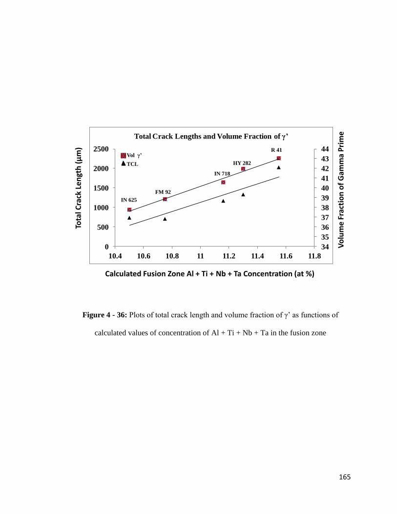
165
34
35
36
37
38
39
40
41
42
43
44
0
500
1000
1500
2000
2500
10.4 10.6 10.8 11 11.2 11.4 11.6 11.8
Total Crack Lengths and Volume Fraction of γ’
X Vol γ’
TCL
Vo
lum
e F
ract
ion
of
Gam
ma
Pri
me
Calculated Fusion Zone Al + Ti + Nb + Ta Concentration (at %)
Tota
l Cra
ck L
en
gth
(μ
m)
IN 625
IN 718
FM 92
HY 282
R 41
Figure 4 - 36: Plots of total crack length and volume fraction of γ‟ as functions of
calculated values of concentration of Al + Ti + Nb + Ta in the fusion zone

166
Vo
lum
e F
ract
ion
of
Gam
ma
Pri
me
Experimental Fusion Zone Al + Ti + Nb + Ta Concentration (at %)
20
25
30
35
40
7.5 8 8.5 9 9.5 10 10.5
Volume Fraction of Gamma Prime as a Function of
Experimental Fusion Zone Al+Ti +Nb + Ta Content
Figure 4 - 37: A plot of volume fraction of γ‟ as a function of experimentally determined
concentration of Al + Ti + Nb + Ta in the fusion zone

167
The second effect of the variation in concentration of Al + Ti + Nb + Ta on the
precipitation of γ‟ particles relates to the solvus of the precipitate. The higher the
concentration of Al + Ti + Nb + Ta, the higher the solvus of γ‟ precipitate. For example,
the solvus of γ‟ precipitate in HY 282 (Al + Ti + Nb + Ta = 6.24 at.%) and IN 738 (Al +
Ti + Nb + Ta = 12.46 at.%) are 997oC and 1165
oC, respectively [173]. Higher γ‟ solvus
suggests that the precipitates could have started to form at higher temperatures. The
generation of tensile stresses, which eventually leads to HAZ intergranular cracking in
nickel-base superalloys, does not generally start until the weld begins to cool [175]. The
alloy remains susceptible to cracking until it is cooled down to the ductility recovery
temperature (DRT), where most of the intergranular liquid has been resolidified. The
difference between the peak temperature reached, Tp and the DRT is referred to as the
brittle temperature range (BTR). The DRT in IN 738 superalloy was found to be as low
as 1000oC [176]. Formation of γ‟ precipitates at higher temperatures within the BTR can
contribute significantly to the on-cooling tensile stresses, thereby resulting in higher
susceptibility to HAZ cracking.
The observation of a relationship between HAZ cracking susceptibility and the variation
in concentration of Al + Ti + Nb + Ta in the weld metals, coupled with the correlation
between this variation and the precipitation of γ‟ particles, suggests that γ‟ particles
precipitated in the fusion zone. However, detailed SEM study did not reveal the presence
of γ‟ precipitate in the fusion zone (Figure 4-38). In order to fully understand the
microstructural characteristics of the fusion zone, TEM analysis was carried out, which
shows that γ‟ particles indeed precipitated in the FZ and resulted in significant
precipitation hardening of the weld metals.

168
Figure 4 - 38: SEM micrograph of the fusion zone, showing carbides but no γ‟ particles

169
4.3.3 TEM Study of γ’ Precipitation
The results of the TEM analysis that was performed on the fusion zone of weldments
made with all five different filler alloys revealed the presence of nanosize spherical γ‟
particles in the weldments. Dark field TEM images and SADPs taken from different zone
axis, all showing superlattice reflections of γ‟ particles, confirm that the precipitate is
present in the fusion zone for all the 5 filler alloys (Figures 4-39 to 4-43). The results
revealed that the largest average particle diameter was observed in the material that was
welded with Rene 41 filler alloy. The average particle diameter in the weld metal with
Rene 41 appeared to be of the order of about 10 nm. A qualitative observation of the dark
field images (Figures 4-39 to 4-43) also suggests that the extent of γ‟ precipitation varied
with the concentration of Al + Ti + Nb + Ta , with the largest amount appearing to have
precipitated in the material welded with Rene 41 filler alloy and reduced with a reduction
in the concentration of Al + Ti + Nb + Ta. Precipitation hardening generally occurs when
the motion of a gliding dislocation is impeded by a secondary phase, such as the ordered
L12 intermetallic γ‟ phase in nickel base superalloys [177-180]. The presence of γ‟
particles and the variation in the volume fraction of the precipitate could result in
different precipitation hardening behaviour in the weld metals, which is expected to
reflect in the micro-hardness measured in the fusion zones. The weld metals with higher a
Al + Ti + Nb + Ta concentration, and consequently higher volume fraction of γ‟ particles,
exhibited higher microhardness, while the weld metals with lower Al + Ti + Nb + Ta
concentration exhibited lower microhardness (Figure 4-44). The TEM results and the
observed trend in precipitation hardening are in agreement with both the calculated
volume fractions of γ‟ particles in the weld metals and the TCL measured in the HAZ of

170
[011]
111γ
200γ
011γ’111γ
100γ’
[112]
220γ
111γ
110γ’
021γ’
131γ
Figure 4 - 39: TEM dark field image of the weld metal with Rene 41 filler alloy and
SADPs showing superlattice reflections of γ‟ precipitates

171
[001]
200γ
220γ020γ
010γ’
110γ’
[112]
220γ110γ’
111γ
131γ
201γ’
Figure 4 - 40: TEM dark field image of the weld metal with HY 282 filler alloy and
SADPs showing superlattice reflections of γ‟ precipitates

172
[111]220γ
110γ’022γ
011γ’
022γ
[001]220γ
200γ
020γ
010γ’
110γ’
Figure 4 - 41: TEM dark field image of the weld metal with IN 718 filler alloy and
SADPs showing superlattice reflections of γ‟ precipitates

173
[011]
200γ211γ’
100γ’111γ
111γ
[112]
220γ
131γ
110γ’
021γ’
042γ
Figure 4 - 42: TEM dark field image of the weld metal with FM 92 filler alloy and
SADPs showing superlattice reflections of γ‟ precipitates

174
[001]
220γ
010γ’
100γ’
200γ
020γ
[011]
111γ
100γ’011γ’
022γ200γ
Figure 4 - 43: TEM dark field image of the weld metal with IN 625 filler alloy and
SADPs showing superlattice reflections of γ‟ precipitates

175
0
500
1000
1500
2000
2500
200
250
300
350
400
10.4 10.6 10.8 11 11.2 11.4 11.6 11.8
HV
N o
f th
e W
eld
Met
al
Calculated Fusion Zone Al + Ti + Nb + Ta Concentration (at %)
Tota
l Cra
ck L
en
gth
(μ
m)
HVN
TCL
IN 625
IN 718
FM 92
HY 282R 41
Figure 4 - 44: Plots of weld metal micro-hardness and total crack length as functions of
calculated values of concentration of Al + Ti + Nb + Ta.

176
the welds. This result suggests that lower volume fraction of γ‟ phase produced softer
weld metals and vice versa.
The TEM observations of γ‟ particles in the fusion zone of all the weldments in this work
and the qualitative observation of volume fraction difference corroborate earlier
discussions on the relationship between Al + Ti + Nb + Ta concentration and the volume
fraction of γ‟ particles. The present results show that susceptibility to intergranular
cracking in the HAZ of IN 738 superalloy is dependent on precipitation hardening in the
weld metal, which, in turn, depends on the composition of the filler alloy used during
laser-arc hybrid welding. As discussed earlier, the driving force for HAZ intergranular
cracking is the generation of tensile stresses during weld cooling. A softer weld metal is
expected to accommodate the tensile stresses to a greater extent while a harder weld
metal would tend to offer more restraint to plastic deformation, thereby transferring most
of the on-cooling tensile stresses to the HAZ. This could have resulted in more HAZ
cracking due to the inability of the HAZ to relax the welding stresses. In addition to
metallurgical compatibility of a filler alloy to a base alloy during welding, slow strength
recovery and high-temperature ductility have been identified to be crucial in selecting
appropriate filler alloy composition [181]. An experimental study of problems associated
with welding investment-cast cobalt-base alloys has also shown that softer lower-carbon
filler alloys produce welds that are less susceptible to hot cracking in the HAZ [181]. The
variation in cracking susceptibility observed in the present work can be attributed to the
variation in precipitation hardening behaviour of the weld metals based on Al + Ti + Nb
+ Ta concentration. Aside from the influence of precipitation hardening, the shrinkage,
and the consequent volumetric changes that accompany γ‟ precipitation, is another factor
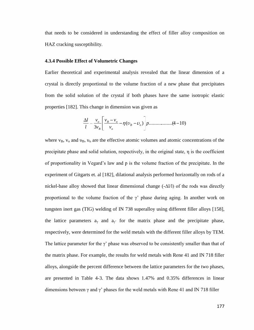
177
that needs to be considered in understanding the effect of filler alloy composition on
HAZ cracking susceptibility.
4.3.4 Possible Effect of Volumetric Changes
Earlier theoretical and experimental analysis revealed that the linear dimension of a
crystal is directly proportional to the volume fraction of a new phase that precipitates
from the solid solution of the crystal if both phases have the same isotropic elastic
properties [182]. This change in dimension was given as
)104........(..........)(3
pv
vv
v
v
l
loB
o
oB
B
o
where vB, vo and υB, υo are the effective atomic volumes and atomic concentrations of the
precipitate phase and solid solution, respectively, in the original state, η is the coefficient
of proportionality in Vegard‟s law and p is the volume fraction of the precipitate. In the
experiment of Gitgarts et. al [182], dilational analysis performed horizontally on rods of a
nickel-base alloy showed that linear dimensional change (-Δl/l) of the rods was directly
proportional to the volume fraction of the γ‟ phase during aging. In another work on
tungsten inert gas (TIG) welding of IN 738 superalloy using different filler alloys [158],
the lattice parameters aγ and aγ‟ for the matrix phase and the precipitate phase,
respectively, were determined for the weld metals with the different filler alloys by TEM.
The lattice parameter for the γ‟ phase was observed to be consistently smaller than that of
the matrix phase. For example, the results for weld metals with Rene 41 and IN 718 filler
alloys, alongside the percent difference between the lattice parameters for the two phases,
are presented in Table 4-3. The data shows 1.47% and 0.35% differences in linear
dimensions between γ and γ‟ phases for the weld metals with Rene 41 and IN 718 filler

178
Table 4 - 3: Lattice parameters of γ and γ‟ phases in weld metals of TIG welded IN 738
superalloy with 2 different filler alloys [158]
Parameter )(a
o
A
(hkl-220)
)(a '
o
A
(hkl-110)
%100a
aa '
Rene 41 filler 3.598 3.5458 1.47
IN 718 filler 3.5960 3.5833 0.35

179
alloys, respectively. This also represents about 4.35% and 1.06% differences between the
volumes of unit cells of γ and γ‟ phases for the two weld metals, respectively. In addition,
the result suggests a higher volume change when Rene 41 filler alloy was used.
Therefore, it can be reasonably purported that the precipitation of γ‟ phase from the γ
matrix would be accompanied by significant shrinkage and volumetric changes during
precipitation, and these are expected to be proportional to the volume of γ‟ phase. In the
present work, differences in the amount of volumetric changes that occurred during weld
cooling as a result of variation in γ‟ volume fraction in the weld metals could be a key
factor that contributed to HAZ cracking susceptibility. Shrinkage usually results in tensile
stress generation, which could be more easily accommodated by a softer and more ductile
weld metal, and prevent excessive tensile loading of the crack-susceptible HAZ.

180
4.4 Post-Weld Heat Treatment (PWHT) Behaviour of the Laser-Arc Hybrid Welded
Material
4.4.1 Introduction
In section 4.2, a complete discussion on the development of an industrially feasible and
effective pre-weld thermal treatment procedure (FUMT) was provided. Post-weld heat
treatment (PWHT) of fusion welded precipitation strengthened nickel-base superalloys is
a standard industry practice. PWHT assists in relieving residual welding stresses,
homogenizing the microstructure and restoring mechanical strength [183, 184]. IN 738
superalloy is usually subjected to PWHT consisting of resolutionizing at 1120oC for 2 h
followed by aging at 845oC for 24 h. Previous PWHT studies of IN 738 materials that
were given other pre-weld heat treatments, and those conducted on other precipitation
strengthened nickel-base superalloys revealed the occurrence of PWHT cracking [184-
186]. Therefore, it is important to examine the PWHT behaviour of the laser-arc hybrid
welded IN 738 material subjected to the pre-weld FUMT treatment. Standard PWHT was
applied to the FUMT-treated laser-arc hybrid welded IN 738 superalloy. The
performance of the FUMT-treated material after PWHT was also compared to that of
SHT-treated material. The microstructure of the FUMT material after PWHT is discussed
first, followed by the results of the assessment of PWHT cracking.
4.4.2 Microstructural Analysis of Welds of the FUMT Treated IN 738 Superalloy
after Post-Weld Heat Treatment
SEM microstructural analysis of the base alloy, the HAZ and the weld metal of the
FUMT-treated material after PWHT was carried out. The microstructure of the base alloy
after PWHT is presented in Figure 4-45. It is seen that the γ‟ phase is distributed in two

181
a
b
Figure 4 - 45: Microstructure of the base IN 738 material after PWHT showing (a) MC
Carbides and γ‟ precipitate (b) γ-γ‟eutectic

182
modes, namely, primary γ‟ and very fine secondary γ‟ precipitates. The blocky MC
carbides and γ-γ‟ eutectic also persisted in the alloy after the PWHT. The SEM image in
Figure 4-46 shows a crack path in the HAZ. One of the major characteristics of the HAZ
is the significant re-precipitation of γ‟ in all the regions previously enriched in γ‟-forming
elements as a result of dissolution of the precipitates during welding. Figure 4-46b shows
that the re-precipitation of γ‟ particles occurred along the crack path where γ‟ liquation
would have occurred during welding.
The microstructure of the fusion zone consisted of Ti-rich MC carbide that was
previously identified by TEM in section 4.1 and a bimodal distribution of γ‟ precipitates.
Spherical γ‟ precipitates of sizes up to about 0.4 μm were observed to be distributed
along the interdendritic regions of the fusion zone, while finer spherical precipitates of
less than 0.1 μm in size mainly occupied the dendrite core (Figures 4-47a and 4-47b). The
observation of larger size γ‟ particles in the interdendritic region is consistent with the
microsegregation pattern in the fusion zone of the as-welded alloy as reported in the
earlier part of this work (Section 4.1). The γ‟-forming elements Al, Ti, Nb and Ta were
observed to partition into the interdendritic regions of the fusion zone. Higher amounts of
the γ‟-forming elements would result in higher volume fraction and size of γ‟ precipitates
and this could be responsible for the difference in sizes of the precipitates in different
regions of the fusion zone. Also, some primary MC carbides that did not dissolve in the
fusion zone during welding were observed in the PWHT material as well (Figure 4-47c).
It has been suggested that re-precipitation of γ‟, such as observed in the post-weld heat
treated IN 738 superalloy in this work, depletes the surrounding matrix of γ‟-forming
elements and causes a decrease in lattice parameter of the matrix, which results in a net

183
Reprecipitated γ’
a
b
Figure 4 - 46: (a) HAZ microstructure, showing a crack path and re-precipitation of γ‟
particles in the vicinity of the crack and other HAZ regions (b) the inset in (a)

184
a
b
c
Figure 4 - 47: SEM Micrographs of the fusion zone (FZ) of the PWHT material, showing
(a) an overview of the FZ microstructure, (b) the inset in (a), and (c) primary MC Carbide

185
contraction [183]. This aging contraction generates high stresses and strains in the
material. Aging contraction stresses, residual welding stresses and thermal stresses have
been identified as key factors contributing to PWHT cracking in many nickel-base
superalloys [183-186]. PWHT cracking occurs when these stresses are preferentially
relaxed in the HAZ, where the grain boundaries have been previously embrittled by
various metallurgical reactions [187]. As mentioned earlier, PWHT cracking
susceptibility of the welded alloy was assessed. The results are presented next.
4.4.3 Assessment of PWHT Cracking in the Welded FUMT Material
In section 4.2, it was shown that the new FUMT treatment produced an improvement of
up to about 80% reduction in HAZ cracking susceptibility in IN 738 superalloy during
laser-arc hybrid welding, compared to the cracking susceptibility of the SHT material.
The results of the PWHT that was carried out in this work showed that the resistance of
the FUMT material to HAZ intergranular cracking is not compromised during PWHT.
Figure 4-48 shows a comparison of total crack lengths (TCLs) measured in the HAZ of
post-weld heat treated SHT and FUMT materials, which suggests that the FUMT material
is not only resistant to cracking during welding but also resistant to PWHT cracking. The
measured TCLs in FUMT materials before and after PWHT showed no significant
increase in cracking after PWHT (Figure 4-49). The resistance of the FUMT material to
PWHT cracking can be attributed to the superior microstructural characteristics of the
newly developed heat treatment, as discussed in detail earlier in section 4.2. Studies have
shown that the pre-weld condition of the base metal is an important factor that affects
PWHT cracking [187]. Resistance to PWHT cracking was observed in Rene 41 following
slow cooling from solution annealing temperature, which produced coarse overaged γ‟

186
To
tal C
rack
Le
ngt
h (μ
m)
Heat Treatment
0
1000
2000
3000
4000
5000
6000
7000
8000
9000
10000
SHT FUMT
Figure 4 - 48: Total crack lengths in the HAZ of post-weld heat treated SHT and FUMT
materials

187
Tota
l Cra
ck L
engt
h (μ
m)
Heat Treatment
0
200
400
600
800
1000
1200
1400
1600
As-welded PWHT
Figure 4 - 49: Total crack lengths in the HAZ of as-welded and post-weld heat treated
FUMT material

188
precipitates and resulted in a softer base metal condition [187, 188]. It was suggested that
stress relaxation during PWHT would be transferred to the weaker, overaged and more
ductile base metal since the base metal will not undergo any significant increase in
strength while the HAZ will during aging. In this work, the FUMT treatment produced an
overaged condition in IN 738 superalloy. Figure 4-50 shows the hardness of IN 738
superalloy subjected to the SHT and FUMT treatments. The FUMT material was found to
be significantly softer than the SHT material, which suggested that the better
performance of the FUMT treatment during PWHT can be related to its superior
microstructural characteristics. The current results revealed that the newly developed
FUMT treatment procedure, coupled with the selection of an appropriate type of filler
alloy would assist in reducing HAZ intergranular cracking both during laser-arc hybrid
welding and during PWHT of the laser-arc hybrid welded IN 738 superalloy.

189
HV
N1
0
250
300
350
400
450
500
SHT FUMT
Figure 4 - 50: Vickers hardness of SHT and FUMT base materials

190
CHAPTER 5
SUMMARY AND CONCLUSIONS
The outcome of this research can be summarized into the following major findings:
1. Laser-arc hybrid welding produced a desirable weld bead shape and appearance in
nickel-base IN 738 superalloy, similar to the weld profile of a typical laser beam
weld, and no exclusive weld metal cracking was observed. The process was
demonstrated to have great potentials for joining IN 738 superalloy and, possibly,
other nickel-base superalloys.
2. Elemental partitioning pattern in the fusion zone, as studied by EPMA and the
calculation of the total volume fraction of the weld metal that resulted from
welding filler alloy consumption, showed that Ti, Ta, Nb, Mo, Al and Zr
partitioned into the interdendritic regions. This elemental partitioning pattern is in
agreement with existing theoretical and experimental works on microsegregation
of different elements during solidification of various alloys.
3. SEM and TEM examination of the weld fusion zone in an SHT-treated IN 738
material welded with IN 718 filler alloy revealed the presence of sub-micrometer
size secondary solidification reaction constituents that include MC-type carbides.
Formation of MC type carbides in the interdendritic regions of the fusion zone
due to microsegregation of carbide-forming elements such as Ti, Ta and Nb was
observed in all weldments in this study.

191
4. Although exclusive fusion zone cracking did not occur during laser-arc hybrid
welding of IN 738 superalloy, HAZ intergranular liquation cracking occurred,
which is a major problem that needs to be addressed in order to maximize the
benefits of the laser-arc welding process and improve the weldability of the alloy.
5. An important factor contributing to intergranular liquation, and hence
intergranular liquation cracking, in the HAZ during welding is the significant non-
equilibrium liquation of second phases including γ‟ precipitates, MC carbides and
M2SC sulphocarbides, γ-γ‟ eutectics and borides that were present in pre-weld
materials.
6. The contribution of the decomposition of borides to intergranular liquation in IN
738 superalloy is very significant in that it could increase the temperature range
over which non-equilibrium HAZ intergranular liquation occurs through the
release of elemental boron into the grain boundaries. Gleeble physical simulation
results showed that non-equilibrium liquation was more severe in the vicinity of
decomposed borides in the alloy and could occur at temperatures as low as
1150oC.
7. Elimination of borides in IN 738 superalloy is critical for developing a pre-weld
heat treatment that reduces HAZ cracking sensitivity for the alloy. Controlling the

192
amount of borides in the alloy is achievable during heat treatment by a careful
selection of temperature and cooling rate.
8. A major finding in this work is the development of a new pre-weld thermal
treatment procedure (1120oC / 16 h / FC), designated as FUMT, which is both
industrially feasible and effective in drastically reducing HAZ intergranular
liquation cracking in IN 738 superalloy during laser-arc hybrid welding.
9. The newly developed FUMT pre-weld treatment is not only effective in reducing
HAZ liquation cracking during welding; laser-arc hybrid welded IN 738 materials
that were subjected to the FUMT treatment were also found to be resistant to post-
weld heat treatment (PWHT) cracking.
10. Propensity for HAZ cracking in IN 738 superalloy also depends, to a significant
degree, on the composition of the filler alloy used during welding. Filler alloys
with less Al + Ti + Nb + Ta concentrations were observed to produce welds that
were less susceptible to HAZ cracking than those with higher Al + Ti + Nb + Ta
concentrations.
11. Thermodynamic temperature step calculation of the volume fraction of γ‟
particles in weldments made with 5 different filler alloys, namely IN 625, FM 92,
IN 718, HY 282 and Rene 41, showed that HAZ cracking varied in the same
manner as the calculated value of γ‟ volume fraction varied with the concentration
of Al + Ti + Nb + Ta in the weld metals produced by the filler alloys.

193
12. While SEM was unable to resolve the γ‟ particles that were present in the fusion
zone, TEM dark field images and SADPs revealed that nanosize γ‟ particles
formed in the weld metals of all the 5 filler alloys used. The TEM data is in
agreement with thermodynamic calculations. Variation in HAZ cracking
susceptibility when different filler alloys were used can be reasonably attributed
to variation in the extent of precipitation hardening produced by the re-
precipitation of γ‟ phase in the weld metals.
13. Softer weld metals (with lower γ‟ volume fraction) produced by lower Al + Ti +
Nb + Ta concentration appear to accommodate the on-cooling tensile stresses to a
greater extent, compared to weld metals with higher Al + Ti + Nb + Ta
concentration, which tend to offer more restraint to plastic deformation, thereby
transferring most of the tensile stresses to the HAZ.
14. Shrinkage, and the consequent volumetric changes, due to γ‟ precipitation in the
weld metals could have contributed to excessive tensile loading of the crack-
susceptible HAZ, which would also depend on the volume fraction of precipitated
γ‟ particles.
15. The newly developed FUMT treatment procedure, coupled with the selection of
an appropriate type of filler alloy would assist, significantly, in reducing HAZ
intergranular cracking both during laser-arc hybrid welding and during PWHT of
the laser-arc hybrid welded IN 738 superalloy.

194
CHAPTER 6
SUGGESTIONS FOR FUTURE WORK
1. All welding runs in this present work were carried out using the same set of
welding parameters, while the IN 738 material was subjected to different pre-weld
heat treatments, resulting in different microstructural characteristics. Additionally,
filler alloys of different compositions were used to alter the composition of the
weld metals. The improvement in weldability that was realized in this work
resulted from microstructural modifications. However, weldability improvement
can also be achieved by process optimization. The welding parameters used in
this work were results of several preliminary trials performed at the beginning of
the work, which produced sound joints. Nevertheless, the welding might not have
been conducted under optimum process conditions. It is therefore recommended
that process parameter optimization should be carried out in order to determine
the effect of welding parameters on weldability.
2. This present work focused on laser-arc hybrid welding of polycrystalline nickel-
base IN 738 superalloy. However, the alloy is also manufactured in forms of
directionally solidified (DS) and single crystal (SX) alloys. It is recommended
that this study be extended to studying the effect of grain structure on
microstructural response and weldability of the alloy during laser-arc hybrid
welding.

195
3. The results of this work suggest that laser-arc hybrid welding has a great potential
for joining nickel-base superalloys for aerospace applications. Due to the limited
information about the joining of nickel alloys by this process, it is required that
extensive research be carried out on other nickel-base alloys to provide
appropriate information on the weldability of each alloy during the process.
4. The new pre-weld thermal treatment procedure that was developed in this work
was found to be effective in drastically reducing HAZ intergranular liquation
cracking during laser-arc hybrid welding. Since the mechanism of HAZ liquation
cracking is the same in the alloy irrespective of the type of fusion welding
technique used, it is suggested that the new heat treatment be applied to other
fusion welding techniques. This should also require significant weldability
studies.
5. A comprehensive study of the mechanical behaviour of laser-arc hybrid welded
IN 738 superalloy subjected to the newly developed heat treatment is
recommended. This can include high and low temperature tensile testing, high
cycle and low cycle fatigue studies, creep testing, etc.

196
REFERENCES
[1] E.W. Ross and C.T. Sims: “Nickel-Base Alloys” in Superalloys II: High
Temperature Materials for Aerospace and Industrial Power, A Wiley-Interscience
publication, 1987, p.97
[2] M. Prager and C. S. Shira: Weld. Res. Council Bull, 1968, vol. 128, p.1
[3] A Thakur, N.L. Richards and M.C. Chaturvedi: International Journal for the
Joining of Materials, 2003, vol. 15, p.21
[4] O.A. Ojo, N.L. Richards and M.C. Chaturvedi: Mater. Sci. Technol., 2004, vol.
20, p.1021
[5] E.A. Bonifaz and N.L. Richards: International Journal of Applied Mechanics,
2010, vol. 2, p.807
[6] K.C. Antony and G.W. Goward: Superalloys 1988, The Metallurgical Society,
p.745
[7] W.M. Steen: J. Appl. Phys., 1980, vol. 51, p.5636
[8] M. Eboo, W.M. Steen and J. Clarke: Advances in Welding Processes Fourth
International Conference, Harrogate, 9-11 May 1978, p.257
[9] W.M. Steen and M. Eboo: Metal Construction, 1979, vol. 7-7, p.332
[10] B. Ribic, T.A. Plamer and T. DebRoy: International Materials Review, 2009, vol.
54, p.223
[11] C. Bagger and F.O. Olsen: Journal of Laser Applications, 2005, vol. 17, No. 1, p.2
[12] H. Staufer: Weld. J., 2007, vol. 86, No. 10, p.36
[13] Mahrle and E. Beyer: Journal of Laser Applications, 2006, vol. 18, p.169

197
[14] T. Ishide, S. Tsubota, M. Watanabe and K. Ueshiro: Journal of the Japan Welding
Society, 2003, vol. 72, No. 1, p.22
[15] J. Defalco: Weld. J., 2007, vol. 86, No 10, p.47
[16] S. Webster: Ironmaking and Steelmaking, 2007, vol. 35, No. 7, p.496
[17] R. Brockmann: Welding and Cutting, 2009, No. 4, p.192
[18] A.N. Nazmul and K. Young-Pyo: Australasian Welding Journal, 2005, vol. 50,
p.22
[19] E.F. Bradley, Superalloys: A technical Guide, ASM International, Metals Park,
OH, 1988
[20] Alloy IN 738: A Technical Data, INCO, New York, p.1
[21] G. C. Bieber, R.J. Mihalisin, 2nd International Conference on the Strength of
Metals and Alloys, Asilomer, ASM Vol. IV, p. 1031
[22] O.A. Ojo: Ph.D. Thesis, University of Manitoba, Canada, 2004
[23] A.T. Egbewande: MSc Thesis, University of Manitoba, Canada, 2008
[24] O.T. Ola: MSc Thesis, University of Manitoba, Canada, 2010
[25] W. F. Smith: Structure and Properties of Engineering Alloys, 2nd
Ed, New York :
McGraw-Hill, c1993, p.504
[26] W. Hoffelner, E. Kny, R. Stickler, W.J. McCall: The Effect of Aging Treatment
on the Microstructure of the Ni-base Superalloy IN 738, Z. Werkstofftech 1979,
Vol. 10, p. 84
[27] R.C. Reed: The Superalloys: Fundamentals and Applications, Cambridge
University Press, 2006, p. 35

198
[28] R.F. Decker: Strengthening Mechanisms in Nickel-Base Superalloys, Climax
Molybdenum Company Symposium, Zurich, May 5-6, 1969
[29] D.S. Paulonis, J.M. Oblak and D.S. Duvall: Trans. ASM, 1969, Vol. 62, p.611
[30] M.J. Donachie and S.J. Donachie, Superalloys: A Technical Guide, 2nd
Edition,
ASM International, 2002 p.31
[31] T.J. Garroshen, G.P. McCarty: Metall. Mater. Trans., 1985, Vol. 16A, p.1213
[32] W.C. Hagel, H.J. Bettie: Iron and Steel Institute Special Report, London, 64, p.98
[33] J.M. Fragomeni: Recent Advances in Solids and Structures, 1999, Vol. 398, p.179
[34] B. Reppich, P. Schepp and G. Wehner: Acta Metall., 1982, Vol. 30, p.95
[35] E. Nembach, S. Schanzer, W. Schroer and K. Trinckauf: Acta Metall., 1988, Vol.
36, No. 6, p.1471
[36] A.J. Ardell: Metall. Trans. A, 1985, Vol. 16A, p.2131
[37] O. Wouters: Rijksuniversiteit Groningen, “Dislocations and Precipitation
Hardening” in Plasticity in Aluminum Alloys at Various Length Scales, Ph.D.
Thesis, 1997, p.25
[38] J.L. Castagne: J. De. Physique, 1966, Vol. 27, p.C3 233
[39] A.J. Ardell, V. Munjal and D.L. Chellman: Metall. Trans. A, 1976, Vol. 7A,
p.1263
[40] A. Melander and P.A. Person: Metal. Sci. J., 1978, Vol. 13, p.391
[41] J.L. Castagne, F. Lecroisey and A. Pineau: C. R. Acad. Sci. Paris, 1968, Vol. 266,
p.510
[42] V. Munjal and A.J. Ardell: Acta Metall., 1975, Vol. 23, p.513

199
[43] J.S. Zhang, Z.Q. Hu, Y. Murata, M. Morinaga, N. Yukawa: Metall. Mater. Trans.,
1993, Vol. 24A, p. 2443
[44] R. Sallemark, Progress Report 2 Cost 50 Programme Sweden, 1975.
[45] R. Rosenthal, D.R.F. West: Mater. Sci. Technol., 1999, Vol. 15, p.1387.
[46] J.M. Larson: Metall. Mater. Trans., 1976, Vol. 7A, p.1497
[47] W.C. Johnson, J.E. Doherty, B.H. Kear, A.F. Giamei: Scripta Metall., 1974, Vol.
8, p.971
[48] J.E. Doherty, B.H. Kear, A.F. Giamei, C.W. Steinke: “Effect of Surface
Chemistry on Grain Boundary Strength”, Grain Boundaries in Engineering
Materials, Claitor‟s Publishing Div., 1975
[49] A.W. Thompson: Acta Metall., 1975, Vol. 28, p.607
[50] J.W. Schultz, University of Michigan, Uni. Microfilms, Ann Arbor, PhD Thesis,
1965
[51] H.R. Zhang, O.A. Ojo, M.C. Chaturvedi: Scripta Mater., 2008, Vol.58, p.167
[52] K. Masubuchi: Encyclopedia of Materials Science and Engineering, M.B. Bever
(Editor), 1986, Vol. 7, p.5280
[53] S. Kuo: Welding Metallurgy, 2nd ed., John Wiley & Sons Inc., Hoboken, 2003, p
9.
[54] D.L. Olson, T.A. Siewert, S. Liu and G.R. Edwards (eds): Overview of Weld
Discontinuities, in ASM Handbook, Vol. 6: Welding, Brazing and Soldering, p.
1073

200
[55] K. Easterling: “Introduction to the Physical metallurgy of Welding”, 2nd
Edition,
Copyright Butterworth-Heinemann, 1992
[56] K. Masubuchi: ASM Handbook: Welding, Brazing and Soldering, 1993, Vol. 6,
p.1094
[57] G.J. Davies and J.G. Garland: Int. Metall. Rev., 1975, Vol. 20, p.83
[58] D.C.G. Lees: J. Inst. Metals, 1946, Vol. 72, p.343
[59] A.R.E. Singer and P.H. Jennings: J. Inst. Metals, 1947, Vol. 73, p. 273
[60] M.J. Cieslak: Cracking Phenomena Associated with Welding, ASM Handbook:
Welding Brazing and Soldering, 1993, Vol. 6, p88
[61] K. Nakata and F. Matsuda, Trans JWRI, 1995, Vol. 24, p.83
[62] R.G. Baker: Philosophical Transactions of the Royal Society of London, Series A,
Mathematical and Physical Sciences, 1976, Vol. 1307, p.207
[63] M.C. Chaturvedi: Materials Science Forum, , 2007, Vols. 546-549p.1163
[64] J.J. Pepe and W.F. Savage: Effects of Constitutional Liquation in 18-Ni Maraging
Steel Weldments, Weld. J., 1967, Vo146 (No. 9), p 411-s
[65] W.A. Owczarski, D.S. Duvall and C.P. Sullivan: Weld. J., 1967, Vol. 46, p.423s.
[66] B. Weiss, G.E. Grotke and R. Stickler: Weld. J., 1970, Vol. 49, p.471s.
[67] J.A. Brooks: Weld. J., 1974, Vol. 53, p.517.
[68] R. Nikkalil, N.L. Richards and M.C. Chaturvedi: Metall. Mater. Trans. A, 1993,
Vol. 24A, p.1169.
[69] B. Radhakrishnan and R.G. Thompson: Metall. Mater. Trans. A, 1993, Vol. 24A,
p.1409.

201
[70] K.R. Vishwakarma and M.C. Chaturvedi: in E.A. Loria (Ed.), Superalloys 718,
625, 706 and Derivatives 2005, The Minerals, Metals and Materials Society,
2005, p.637
[71] W. Chen and M.C. Chaturvedi: Metall. Mater. Trans. A, 1998, Vol. 29A, p.743
[72] M. McLean and A. Strang: Metals Technol., 1984, Vol. 11, p. 454
[73] E.D. Hondros and M.P. Seah: in R.W. Chan (Ed): Physical Metallurgy, 3rd
edition, North Holland, Amsterdam, 1984
[74] M.P. Seah and E.D. Hondros: Proc. R. Soc., 1973, Vol. 335A, p.191
[75] D. McLean: Grain Boundaries in Metals, Clarendon Press, Oxford, 1957
[76] J.H. Westbrook and K.T. Aust: Acta Metall., 1963, Vol. 11, p.1115
[77] K.T. Aust, R.E. Hanneman, P. Nissen and J.H. Westbrook: Acta Metall., 1968,
Vol. 16, p.291
[78] R.L. Eadie and K.T. Aust: Scripta Metall., 1970, Vol. 4, p.641
[79] K.T. Aust: Canadian Metallurgical Q., 1974, Vol. 13 (1), p.133
[80] D.C. Paine, G.C. Weatherly and K.T. Aust: J. Mater. Sci., 1986, Vol. 21, p.4257
[81] X. Huang, M.C. Chaturvedi, N.L. Richards and J. Jackman: Acta Mater., 1997,
Vol. 45, p.3095
[82] L. Karlsson and H. Norden: Acta Metall. 1988, Vol. 36, p.1
[83] L. Karlsson and H. Norden: Acta Metall. 1988, Vol. 36, p.13
[84] L. Karlsson: Acta Metall. 1988, Vol. 36, p.25
[85] L. Karlsson and H. Norden: Acta Metall. 1988, Vol. 36, p.35
[86] R.D. Campbell and D. W. Walsh: “Weldability Testing”, in ASM Handbook:
Welding, Brazing and Soldering, Vol. 6, 1993, p.603

202
[87] “Weldability Testing,” Chapter 4, Welding Handbook, Vol. 1, 8th ed., American
Welding Society, 1987
[88] R.D. Stout and W.D. Doty: Weldability of Steels, Welding Research Council,
1987
[89] C.D. Ludin, A.C. Lingenfelter, G.E. Grotke, G.G. Lessmann and S.J. Matthews:
The Varestraint Test, Weld. Res. Counc. Bull., No. 280, 1982
[90] E.F. Nippes and W.F. Savage: Weld. J., 1955, Vol 34 (No. 4), p 183-s
[91] E.F. Nippes, W.F. Savage. and G. Grotke: Bulletin Series Vol 33 (No. 2),
Welding Research Council, 1957
[92] E.F. Nippes, W.F. Savage, and J.M. Paez: Weld. J., 1960, Vol 39 (No. 1), p 31-s
[93] K.C. Wu: Weld. J., 1963, Vol 42 (No. 9), p 392-s
[94] R.F. Fastini and M. Semchyshen: The Effect of Molybdenum on the Continuous
Cooling Transformation of a 0.40% Carbon Steel, ASM Trans. Quart., Sept 1964
[95] D.G. Howden, Isothermal Transformation Characteristics of a Low-Alloy Steel
Using a Weld Thermal Cycle Simulator, Can. Metall. Quart., 1967 , Vol 6 (No. 3)
[96] C.F. Meitzner and A.W. Pense: Weld. J., 1969, Vol 48 (No. 10), p.431-s
[97] A.W. Dix and W.F. Savage: Weld. J., 1973. Vol 52 (No. 3), p 135-s
[98] S.J. Matthews: Weld. J., 1968. Vol 47 (No. 4), p 155-s
[99] K.C. Wu and T.A. Krinke: Weld. J., 1968. Vo147 (No. 6), p 332-s
[100] W.P. Hughes and T.F. Berry: Weld. J., 1967, Vol 46 (No. 8), p 361-s

203
[101] Anon, Computerized Thermal and Mechanical Testing Machine a Significant
Asset in Research, Development and Production, Industrial Heating, 1986, Vol.
53 (No 12), p.28
[102] L.O. Osoba: Ph.D. Thesis, University of Manitoba, Canada, 2012
[103] T. Graf and H. Staufer: Weld J., 2003, Vol. 82, p.42
[104] K. Hakansson, T. Siwecki and D. Stemne: Welding in the World, 2008, Vol. 52,
p.103
[105] A. Nonn, W. Dahl and W. Bleck: Engineering Fracture Mechanics, 2008, Vol. 75,
p.3251
[106] E. W. Reutzel: Advantages and disadvantages of arc and laser welding, in Hybrid
Laser-Arc Welding, F.O. Olsen (ed.), Woodhead Publishing Limited, Abington
Hall, Granta Park, Great Abington, Cambridge, UK, 2009, p.3
[107] D.S. Howse, R.J. Scudamore and G.S. Booth: Proceedings of the Fifteenth
International Offshore and Polar Engineering Conference, Seoul, Korea, June 15-
19 2005, pp.90-95
[108] C. Thorny, T. Seefeld and F. Vollertsen: Welding in the World, 2005, Vol. 49,
p.88
[109] A. Mahrle and E. Beyer: Heat sources of hybrid laser–arc welding processes, in
Hybrid Laser-Arc Welding, F.O. Olsen (ed.), Woodhead Publishing Limited,
Abington Hall, Granta Park, Great Abington, Cambridge, UK, 2009. P.47
[110] J. Greses, P.A. Hilton, C.Y. Barlow and W.M. Steen: „Spectroscopic studies of
plume/ plasma in different gas environments‟, Proceedings of the International
Congress on Lasers and Electro-Optics (ICALEO 2001), p.10
204
[111] K.E. Lahti: Svetsaren, 2003, Vol. 58, p.22
[112] J. Pilarczyk, M. Banasik and J. Dworak: Welding International, 2008, Vol. 22,
p.388
[113] L.E. Stridh: Materials Science Forum, 2007, Vols. 539-543, p.3991
[114] M.S. Surendar: Yosetsu Gakkai Shi, 2010, Vol. 79, p.14
[115] T. Ishide, S. Tsubota and M. Watanabe: Proc. of SPIE (First International
Symposium on High-Power Laser Macroprocessing), Osaka, JLPS, 2002, Vol.
4831, p.347
[116] M. Kutsuna and L. Chen: IIW, 2002, Doc XII-1708-02
[117] J.R. Biffin and R.P. Walduck: Proceedings EUROJOIN 2, 2nd
European
Conference on Joining Technology, Firence, Italy, 16-18 May 1994, p.295
[118] S.E. Nielsen, M.M. Andersen, J.K. Kristensen and T.A. Jensen: International
Institute of Welding, IIW Document, XII 1731-02, 2002
[119] S. Fujinaga, R. Ohashi, S. Katayama and A. Matsunawa: LAMP 2002
Proceedings, First International Symposium on High Power Laser
Macroprocessing – Proc. SPIE, 2002, Vol. 4831, pp.301-306
[120] L. Liming, W. Jifeng and S. Gang: Mater. Sci. and Eng. A, 2004, Vol. 381, p.129
[121] C.V. Hyatt, K.H. Magee, J.F. Porter, V.E. Merchant and J.R. Matthews: Weld. J.,
2001, Vol. 80, no. 7, p.163s
[122] G. Campana, A. Fortunato, A. Ascari, G. Tani and L. Tomesani: Journal of
Materials Processing Technology, 2007, Vol. 191, p.111

205
[123] K.H. Magee, V.E. Merchant and C.V. Hyatt: Proceedings of ICALEO 1990,
Boston, MA (Laser Institute of America, 1990), pp. 382-399
[124] T. Jokinen, P. Jernstrom, M. Karhu, I. Vanttaja and V. Kujanpaa: Proc. 1st Int.
Symp. on „High-power laser macroprocessing‟, Osaka, Japan, May 2002, Osaka
University, p.307
[125] Y. Naito, S. Katayama and A. Matsunawa: First International Symposium on
High-Power Laser Macroprocessing – Proceedings of SPIE, 2003, Vol. 4831,
p.357
[126] A. Fellman, P. Jernstrom and V. Kujanpaa: Proceedings 9th
NOLAMP,
Conference on Laser Materials Processing in the Nordic Countries, Trondheim,
Norway, 4-6 August 2003, p.103
[127] J. Alexander and W.M. Steen: Institution of Metallurgists, Great Britain: Joining
of Metals; Practice and Performance, Spring Residential Conference, 1981, No.
18, p.155
[128] S. Katayama, Y. Naito, S. Uchiumi and M. Mizutani: Transactions of JWRI,
2006, Vol. 35, No. 1, p.13
[129] M. Gao and X. Y. Zeng, Effect of shielding gas on hybrid laser–arc welding, in
Hybrid Laser-Arc Welding, F.O. Olsen (ed.), Woodhead Publishing Limited,
Abington Hall, Granta Park, Great Abington, Cambridge, UK, 2009, p.85
[130] D. Petring, C. Fahrmann, N. Wolf and R. Poprawe: Proc of the 22nd Int. Congress
on Applications of Lasers and Electro-Optics (ICALEO), Jacksonville, LIA,
2003, Section A, 1-10 (CD:301)

206
[131] H. Staufer, Industrial robotic application of laser-hybrid and laser-hybrid-tandem
welding, in Hybrid Laser-Arc Welding, F.O. Olsen (ed.), Woodhead Publishing
Limited, Abington Hall, Granta Park, Great Abington, Cambridge, UK, 2009,
p.192
[132] J. K. Kristensen, Shipbuilding applications of hybrid laser–arc welding, in Hybrid
Laser-Arc Welding, F.O. Olsen (ed.), Woodhead Publishing Limited, Abington
Hall, Granta Park, Great Abington, Cambridge, UK, 2009, p.178
[133] L. Liu, Hybrid welding of magnesium alloys, in Hybrid Laser-Arc Welding, F.O.
Olsen (ed.), Woodhead Publishing Limited, Abington Hall, Granta Park, Great
Abington, Cambridge, UK, 2009, p.143
[134] Jiaming Ni, Zhuguo Li, Jian Huang and Yixiong Wu: Materials and Design, 2010,
Vol. 31, p.4876
[135] C. Pascal, C. Merlet, R-M. Marin-Ayral, J-C. Tedenac and B. Boyer: Microchim.
Acta, 2004, vol. 145, p.147
[136] N. Saunders, X. Li, P. Miodownik and J. Ph. Schille: “Proc. Symp. Materials
Design Approaches and Experiences”, eds J.-C. Shao et. al., 2001, p.185,
Warrendale, PA, TMS
[137] G.D. Pigrova: Metal Science and Heat Treatment, Plenum Publishing
Corporation, 1985, vol. 27 (9), p.750
[138] Y.N. Ahn and C. Kim: Materials Science Forum, 2011, Vol. 695, p.247-
[139] M.C. Flemings, Solidification Processing, McGraw-Hill, New York, 1974.
[140] P.N. Quested and M. McLean: Conf. on Solidification Technology in the Foundry
and Cast House, The Metals Society, London, 1980, p.586

207
[141] L. Liu and F. Sommer: Scripta Metallurgica et Materialia, 1994, Vol. 30, p.587
[142] H.D. Brody: in Advances in Welding Science and Technology, S.A. David, ed.,
ASM international, Metals Park, OH, 1986, p.83
[143] R. Nikkalil, N.L. Richards and M.C. Chaturvedi: Metallurgical Transactions A,
1993, vol. 23A, p.1169
[144] E. Scheil: Z. Metallk., 1942, vol. 34, p.70
[145] J.N. DuPont, C.V. Robino, A.R. Marder and M.R. Notis: Metall. Mater. Trans. A,
1998, vol. 29 A, p.2797
[146] H.D. Brody and M.C. Flemings: Trans. AIME, 1966, vol. 236, p.615
[147] O.A. Ojo, N.L. Richards and M.C. Chaturvedi: Metall. Mater. Trans. A, 2006,
vol. 37A, p.421
[148] R.K. Sidhu, O.A. Ojo and M.C. Chaturvedi: Metall. Mater. Trans. A, 2007, vol.
83A, p.858
[149] L. O. Osoba, R.G. Ding and O.A. Ojo: Materials Characterization, 2012, vol. 65,
p.93
[150] G.A. Knornovsky, M. J. Cieslak, T.J. Headley, A.D. Romig, Jr., and W.F.
Hammeter: Metall. Trans. A, 1989, Vol. 20A, p.2149
[151] R.G. Thompson, D.E. Mayo and B. Radhakrishnann: Metall. Trans. A, 1991, vol.
22A, p.557
[152] Y. Nakao and K. Shinozaki: Proc. Int. Conf. on High Temperature Materials,
Liege, Belgium, 1990, p.24
[153] D. Turnbull: J. Chem. Physiol., 1950, vol. 18, p.198

208
[154] W.F. Savage, C.D. Lundin, and A.H. Aronson: Weld. J., 1965, vol. 44, p.175s
[155] W.F. Savage and A.H. Aronson: Weld. J., 1966, vol. 45, p.85s
[156] W.F. Savage, C.D. Lundin, and T.F. Chase: Weld. J., 1968, vol. 47, p.522s
[157] L. Liu, B.L. Zhen, A. Banerji, W. Reif and F. Sommer: Scripta Metall. Mater.,
1994, vol. 30, p.593
[158] K. Banerjee, N.L. Richards and M.C. Chaturvedi: Metall. Mater. Trans. A, 2005,
Vol. 36A, p.1881
[159] W. Wallace, R.T. Holt and T. Terada: Metallography, 1973, vol. 6, p.511
[160] ASM Handbook: “Welding of Nickel Alloys,” Welding, Brazing and Soldering,
1993, Vol. 6, p.740
[161] A.T. Egbewande, H.R. Zhang, R.K. Sidhu and O.A. Ojo, Metall. Mater. Trans. A,
vol. 40A, 2009, p.2695
[162] K. Masubuchi: Analysis of Welded Structures, International Series on Materials
Science and Technology, Vol. 33, Copyright Pergamon Press Ltd, 1980, p.149
[163] K.C. Antony and J.F. Radavich: Superalloy: Metallurgy and Manufacture, B.H.
Kear Ed., Claitor‟s Pub. Division, 1976, p.137
[164] D. McLean: Grain Boundaries in Metals, Clarendon Press, Oxford, 1957
[165] E.D. Hondros, M.P. Seah: Physical Metallurgy, R.W. Chan (Ed), 3rd
edition,
North Holland, Amsterdam, 1984
[166] T.M. Williams, A.M. Stoneham and D.R. Harries: Met. Sci., 1976, Vol. 10, p.14
[167] H.B. Aaron and G.R. Kotler: Metall. Trans., 1971, Vol. 2, p.393
[168] M.J. Whelan: Metal Science Journal, 1969, Vol. 3, p.95

209
[169] A.R. Eivani, H. Ahmed, J. Zhou and J. Duszczyk: Philosophical Magazine, 2010,
Vol. 90, No. 21, p.2865
[170] J.R. Davis: ASM Specialty Handbook – Nickel, Cobalt and Alloys, 2000, p.267
[171] Y.E. Wu and Y.T. Wang: Journal of Materials Engineering and Performance,
2010, Vol. 19, p.1362
[172] M.O. Okubo and H. Uryu: Welding International, 1996, Vol. 10. No. 4, p.274
[173] L.M. Pike: Superalloys 2008, The Minerals, Metals and Materials Society, 2008,
p.191
[174] C. Ravindran and M.C. Chaturvedi: Metall. Trans. A, 1975, Vol. 6, No. 1, p.213
[175] V.P. Demyantsevich: Welding Production, 1969, Vol. 14, No. 3, p.1
[176] O.A. Ojo and M.C. Chaturvedi: Mater. Sci. Eng. A, 2005, Vol. 403, p.77
[177] J.M. Fragomeni: Recent Advances in Solids and Structures, 1999, Vol. 398, p.179
[178] B. Reppich, P. Schepp and G. Wehner: Acta Metall., 1982, Vol. 30, p.95
[179] E. Nembach, S. Schanzer, W. Schroer and K. Trinckauf: Acta Metall., No. 6,
1988, Vol. 36, p.1471
[180] A.J. Ardell: Metall. Trans. A, 1985, Vol. 16A, p.2131
[181] T.F. Chase: “High-Temperature Properties of Welded Cast Co-Base Alloys”,
Superalloys-Processing; Proceedings of The Second International Conference,
The Metallurgical Society AIME, September 18-20, 1972, Seven Springs
Mountain Resort, Champion, PA, p.R1
[182] M.I. Gitgarts, A.V. Tolstoy and V.V. Ivashin: Fiz. Metal. Metalloved, 1972, Vol.
33, No. 4, p.820
[183] L.C. Lim, J.-Z. Yi, N. Liu and Q. Ma: Mater. Sci. Technol., 2002, Vol. 18, p.407

210
[184] R.K. Sidhu, N.L. Richards and M.C. Chaturvedi: Mater. Sci. Technol., 2008, Vol.
24, No. 5, p.529
[185] Y. Nakao: Trans. Japan Weld. Soc., 1988, Vol. 19, No. 1, p.66
[186] R. Kayacan, R. Varol and O. Kimilli: Mater. Res. Bull., 2004, Vol. 39, p.2171
[187] R. Thamburaj, W. Wallace and J.A. Goldak: Int. Metals Rev. 1983, Vol. 28, No.
1, p.1
[188] E.G. Thompson, S. Sunez and M. Prager: Weld. J, 1968, Vol. 47, No. 7, p.299-s

211
RESEARCH CONTRIBUTIONS
CONTRIBUTIONS FROM THIS CURRENT WORK
US PATENT Application No. 61/858042: O.T. Ola, O.A. Ojo, M.C. Chaturvedi
and A. Birur: Pre-Weld Heat Treatment of γ’ Precipitation Strengthened Nickel-
Based Superalloys. (Application Filed)
O.T. Ola, O.A. Ojo and M.C. Chaturvedi: The Role of Filler Alloy Composition
on Laser-Arc Hybrid Weldability of Nickel-Base IN 738 Superalloy, Materials
Science and Technology (Submitted)
O.T. Ola, O.A. Ojo and M.C. Chaturvedi: Laser-Arc Hybrid Weld Microstructure
in Nickel-Base IN 738 Superalloy, Materials Science and Technology, 2013, Vol.
29, No 4, pp.426-438
OTHER CONTRIBUTIONS
Papers in Referred Journals
O.T. Ola, O.A. Ojo and M.C. Chaturvedi. Effect of Deformation Mode on Hot
Ductility of A γ’ Precipitation Strengthened Nickel-Base Superalloy, Materials
Science and Engineering A. (Accepted on June 18, 2013)
O.T. Ola, O.A. Ojo, P. Wanjara and M.C. Chaturvedi: A Study of Linear Friction
Weld Microstructure in Single Crystal CMSX-486 Superalloy, Metallurgical and
Materials Transactions A, 2012, Vol. 43, No 3, pp.921-933

212
O.T. Ola, O.A. Ojo, P. Wanjara and M.C. Chaturvedi: Enhanced Resistance to
Weld Cracking by Strain-Induced Rapid Solidification during Linear Friction
Welding, Philosophical Magazine Letters, 2011, Vol. 91, pp.140-149
O.T. Ola, O.A. Ojo, P. Wanjara and M.C. Chaturvedi: Analysis of Microstructural
Changes Induced by Linear Friction Welding in a Nickel-Base Superalloy,
Metallurgical and Materials Transactions A, 2011, Vol. 42A, pp.3761-3777
Papers in Referred Conference Proceedings
M.Y. Amegadzie, O.T. Ola, O.A. Ojo, P. Wanjara and M.C. Chaturvedi: On
Liquation and Liquid Phase Oxidation during Linear Friction Welding of Nickel-
Base IN 738 and CMSX-486 Superalloys, Superalloy 2012 – The 12th
International Symposium on Superalloys, 9-13 September, 2012, Pennsylvania,
USA, pp.587-594
O.T. Ola, O.A. Ojo, P. Wanjara and M.C. Chaturvedi: Linear Friction Welding of
Single Crystal Nickel-Base CMSX 486 Superalloy, JOM-16 (16th International
Conference on the Joining of Materials), Helsingør-Denmark 10-13 May 2011
O.T. Ola, O.A. Ojo, P. Wanjara and M.C. Chaturvedi: Crack-Free Welding of IN
738 by Linear Friction Welding, Advanced Materials Research, 2011, Vol. 278,
pp.446-453 (Presented at Euro Superalloy 2010)