a small uav deviation control roll research
TRANSCRIPT
A small UAV deviation control roll research
Tianxiang Hu
College of Mechatronic Engineering, Nanjing Institute of Industry Technology, Nanjing 210023,
China
Email: [email protected]
Keywords: UAV; Roll; Flying control; Rectify deviation
Abstract: This paper according to the small UAV structure characteristics, the taxiing control
structure and control law design are studied and proposed front wheel and rudder deviation control
scheme and control structure, analysis, including the front landing gear, pavement condition, brake
system, wind and other factors for correcting deviation control effect influence, based on take-off
and landing and taxiing deviation control take-off characteristics, design the taxiing test scheme.
Introduction
Wheeled landing approach is large and medium-sized UAV using an important landing
approach, the cost is expensive, landing gear system is more complex, and is equipped with brake
system, so ground of ground taxiing control the main wheel differential brake and control method of
rudder combined correction. However, for small wheeled landing mode of the UAV, due to its light
weight, low cost, easy to use and maintenance, the landing gear design is generally relatively simple.
Due to the front wheel and the differential brake can implement the deviation control, front wheel
steering control with quick response, no additional resistance, roll a short distance, differential
brake on the landing gear brake system requirements higher, thus greatly increased the landing gear
of the weight and cost. Using the front wheel steering control of the UAV, can not install the brake
system or modified simple brake system for reduction, because the structure is simple, so the small
wheeled landing UAV usually use this way of deviation correction.
In the present study on man-machine taxiing characteristics, mostly taxiing mathematical
model based on the accurate of taxiing model of UAV Based on. However, because of the UAV in
taxiing process of influencing factors, such as front landing gear overhead back, pavement
condition, wind or other. Therefore, it is very difficult to establish accurate mathematical model.
Especially small unmanned aerial vehicle (UAV), to carry out wind tunnel experiment is not only
long life cycle, and costly, through the taxiing test parameter adjustment is small UAV control law
design is an important method.
Ground control scheme and structure
UAV lateral motion information into the front wheel steering deviation control law and rudder
deviation control law, front wheel steering control and rudder control. At the same time to UAV, by
the two control channel control law operation produced front wheel steering deviation control
instruction and rudder rectifying deviation control instruction, in low-speed taxiing section, front
wheel correction efficiency is high, the rudder authority rate lower, front wheel correction plays a
International Conference on Manufacturing Science and Engineering (ICMSE 2015)
© 2015. The authors - Published by Atlantis Press 1
major role; in the high-speed range, the rudder authority higher rate, because of a surge in the UAV
lift, the pressure of front wheels on the road is very small, so a front wheel steering correction
efficiency is very low, the rudder play main role. In order to ensure seamless handover of UAV in
taxiing of front wheel deviation control and rudder deviation control rudder deviation control law
through the distributor and steering control law together to produce steering control commands,
enter into the front wheel steering mechanism of deflection torque control lateral movement of the
UAV. The UAV lateralization in a safe range. Taxiing in rectifying process, if appear out of the
runway and other emergency situations, the brake control law based on the instruction of lateral
distance and sliding speed are brake, braking instruction enters into the brake mechanism to control
the UAV taxiing speed, ensure that the UAV sliding safety. Here, the brake does not participate in
the lateral control.
The lateral offset based feedback signal, because the front wheel steering control response is
more sensitive, the lateral velocity and yaw rate control to improve the dynamic performance, these
signals into the front wheel steering correction control law, the front wheel steering correction
control law generates front wheel steering control command; in addition, at the same time as the
main lateral offset feedback signal and the yaw angle, yaw rate in rudder deviation control law
direction, because the relatively slow response of rudder control, where the yaw angle and yaw rate
to improve the dynamic performance of control, the rudder deflection correcting control law
generates instructions to enter the rudder rudder loop make rudder yaw moment generated deviation.
In order to realize the smooth transition between front wheel steering control and directional control,
the design of the distributor is that the control parameters of the control parameters of the control
parameters of the steering control system are generated according to a certain transmission ratio.
Taxiing in rectifying process and roll within the loop at the same time, to prevent the aircraft in the
rectification movement due to turn centrifugal force, wind or other factors lead to the roll angle is
too large, so that the risk of rollover occurred in the process of turning.
Taxiing stage, UAV lateral control law for specific expression:
P
cK P K
&R Y Y
f f f fK R K K
R Y
r r r c rK R K K Y
a is for aileron rudder offset value, P is the rolling angular rate, for roll angle, c is the
roll angle commands, p
aK and
aK are aileron differential and the proportional control gain.
f is front wheel steering rudder deflection angle, R is the yaw rate, Y is relative to the
runway center line of the lateral offset, &Y is the lateralization rate available formula obtained:
& sing cY V
gV is the ground speed, c is UAV heading command, C is the current direction of UAV
2
Ground speed.
RKf is the front wheel, the yaw angle rate control gain,
&
fKYis the front wheel side velocity
control gain, and Y
fK is the front wheel side offset control gain.
r is rudder angle, R
rK is the rudder yaw angle rate control gain, and
rK is the rudder yaw
angle control gain, Y
rK is the rudder of a lateral control gain.
a 、 f and r are obtained after the limit, ac 、 fc 、 rc to the output circuit
The design details are as follows:
R R r
r r fK K K
&Y r
f r fK K K
Y Y r
f r fK K K
Y
fK is the distribution coefficient from the rudder to the front wheel.
Ground to adjust the parameters of experimental design
Lateral deviation control requirements
Through the taxiing test to debug control parameters, we need to make clear rectifying control
requirements. In the control of UAV Ground run the requirements as follows:
(1) the yaw rate can not be too large, that is in the process of running the body does not appear
obvious swing;
(2) UAV relative lateral offset to the runway center line to keep in allowable range, prevent
taxiing due to runway Road, crosswind disturbance and other factors make no man-machine
runway.
(3) during taxiing without man-machine nose heading and the runway centerline heading angle
should be in reasonable range, and there should not be a large angle correction or even turning a
dangerous situation.
influence factors of deviation correction
UAV, ground taxiing in, affect the correction control effect of many for the proposed control
scheme, in the test process must focus on four aspects: ①front air back、②pavement condition、
③brake effect、④the gust effect
The direct influence of the size of the front wheel back to the control accuracy, the smaller the
front wheel back to the smaller the better control effect. The empty back and the back of the front
wheel steering gear and the back of the transmission mechanism, the gap between the transmission
rod and the fixed gap between the wheel and the wheel, the two kinds of air return should be
3
considered in the landing gear design, the general should be less than 5.0 .
Pavement condition is mainly considered the influence of pavement slope and pavement
irregularities. Road gradient and the main landing gear rack two machine tire pressure inconsistent
on the control effect of the same, mainly affecting the skating when cornering static error and
different runway pavement different slope, even with a runway in UAV back and forth taxiing
correction effect is also different. Therefore, no man in taxiing must pass free glide tests without
control, continuous commissioning front of zero, to ensure that front zero within the appropriate
range and to eliminate side partial static error. The road bump mainly affects the safety running,
may lead to a significantly uneven pavement before landing gear damage or UAV rollover.
Brake system, though not for left and right wheel differential correction, but because of the left
and right brake mechanism of asymmetry, when in taxiing of emergency deceleration, resulting in
UAV nose to brake torque on the larger side thrash, under the situation of fa st may make UAV
rollover or overshot the runway.
Although the taxiing process time is short, during the period of may by gust effect in
man-machine sloshing, taxi trajectories deviate from the runway center line. Lateral deviation
control should be timely and smoothly will not control back to the safety range, and would not have
a big overshoot.
Test design
As a result of the UAV in take-off and landing phases into the initial state of the ground taxiing,
control parameters test tuning into the focus is different.
The initial conditions for the test of the takeoff section are as follows:
(1) the UAV parked on the runway center line, the lateral offset is almost zero;
(2) the head of the UAV is aligned with the center line of the runway, and the heading deviation
of the center line of the nose and the runway is almost zero.
For take-off period of adjusting parameter test, the elevator shall produce nose down moment,
prevent because skating speed is too fast, no man-machine accidentally took off from the ground.
Send "roll" after the instruction, the UAV taxiing began to accelerate from rest, parking at set speed
after. Gradually increasing the speed of setting the sliding speed until the ground velocity can be
completed.
UAV ground before subjected to Crosswind Effects, there may be a larger lateral partial and the
heading error, so in the design of landing ground taxiing test should be in the UAV to pick up speed
skating to produce certain side partial validation of UAV in the rapid sliding state of cornering
ability.
Parameter design of correction control law
Lateral deviation control law design is to determine the parameters control the gain value in the
law.
In the low-speed taxiing segment, front wheel correction plays a major role, need to determine
RKf 、 &
fKYand
Y
fK . The three parameters are determined by the process:
4
(1)A reference value for the RKf、 &
fKY and Y
fK
(2) RKf determination: UAV in the take-off process, may head swing, adjust the value of
&
fKY , head swing within a reasonable range;
(3) Y
fK determination: UAV in low speed, smooth take-off, but with increasing taxiing speed,
body in on both sides of the runway centerline sloshing, namely "the touch" phenomenon, adjust the
value of &
fKY , the UAV a straight taxiing along the runway center line;
Y
fK is in the roll before, will determine the UAV runway centerline distance, observed during
cornering roll control. If the parameter Y
fK is too large, although the response rate is fast, but it is
easy to generate a large overshoot; if the parameters of Y
fK is too small, the deviation of the
response process is slow, it may affect the take-off safety. Therefore, adjust the Y
fK value, so that
the UAV in the case of the initial side or course deviation can be quickly and without overshoot into
the runway center line.
In the medium and high speed running, the rudder began to need to determine the value of
R
rK 、
rK 、 Y
rK andr
fK rectification. The design of high speed R
rK and
rK design section and the
speed of RKf 、 &
fKY and Y
fK is similar, and will not go. r
fK and front wheel steering actuator to
front wheel drive mechanism, in the same state of the front wheel steering mechanism of conditions,
is the middle speed section taxiing to adjust the parameters of the key. If the speed control
parameters have been determined, the speed skating there head swing, "the touch" control effect is
not too ideal can enlarge or reduce the speed of the corresponding control parameters value, while
at the same time reduce or enlarge the r
fK value to achieve both to ensure low speed correction
effect is ideal and also corrected taxiing speed.
Test Analysis
The design method of control law is applied to the design of the control law of a certain type of
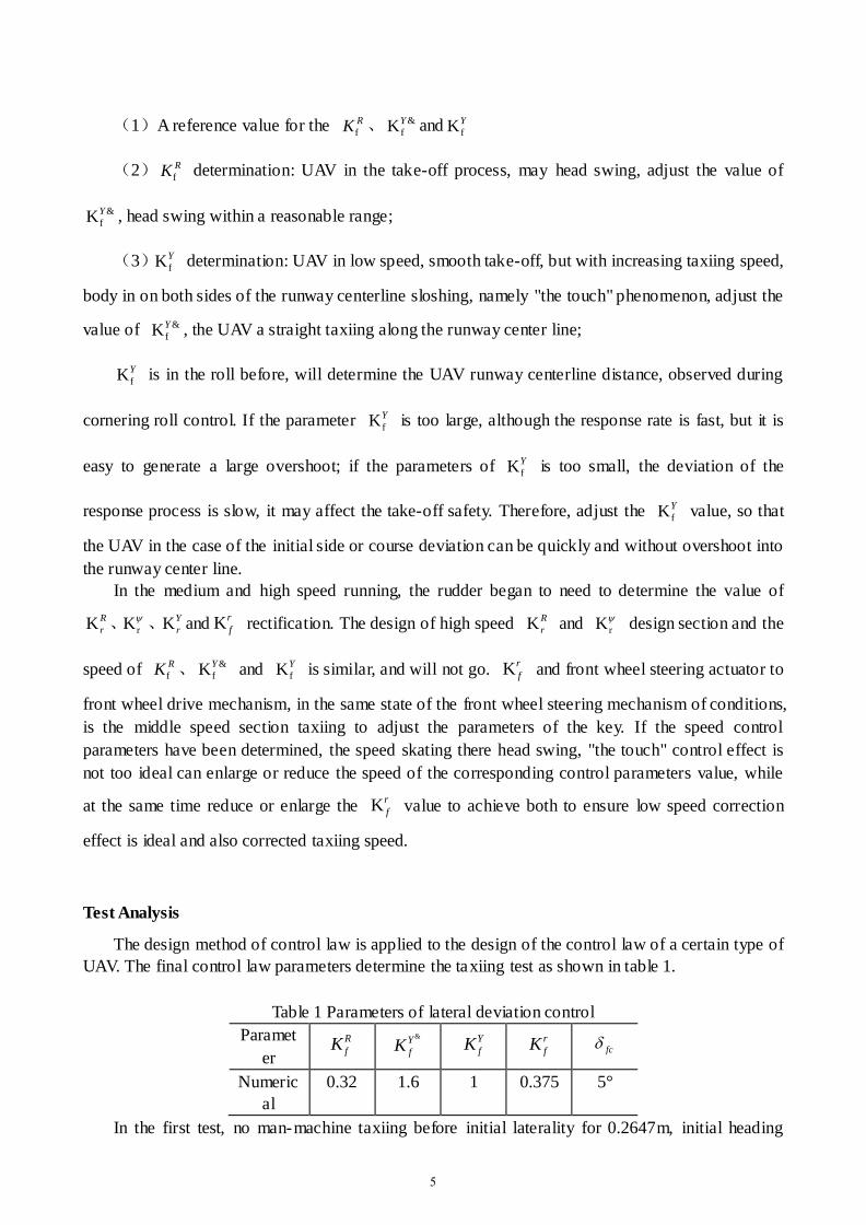
UAV. The final control law parameters determine the taxiing test as shown in table 1.
Table 1 Parameters of lateral deviation control
Paramet
er
R
fK &Y
fK Y
fK r
fK fc
Numeric
al
0.32 1.6 1 0.375 5°
In the first test, no man-machine taxiing before initial laterality for 0.2647m, initial heading
5
error for 211.5 degrees, that is, without man-machine aligned with the runway centerline. UAV
takeoff in the process, the maximum lateral offset is -0.5m, maximum yaw angle rate for -2.893
degrees per second, the maximum deviation in heading for degree -1.215, maximum rolling angle
degree -0.8951, UAV in GS to 28.96m/s from take-off, taxiing of low speed and high speed smooth
transition, meet the take-off requirements.
In the second experiment, landing taxiing data can be seen, the UAV ground before initial
velocity for 21.14m/s and initial lateral partial to -0.97m, initial heading error is 0.23 DEG, taxiing
of maximum lateral offset is -1.677m, maximum yaw angle rate for 3.813 deg / s, the maximum
deviation in heading for 179 degrees, the maximum rolling angle degree -0.941, UAV ground
quickly and smoothly without overshoot of taxied to the runway center line, stop from the runway
centerline of the lateral offset -0.2648m, and taxiing of no obvious head swing, ground taxiing of
safety, not use emergency brake.
Deviation control law parameters, the realization of the front wheel steering control and rudder
control seamless handoff, is designed through the taxiing test parameter adjustment. For UAV actual
landing and taxiing test analysis, verify ground taxiing control scheme and the structure is
reasonable and feasible, and the control law design is simple, effective and good control effect and
meet the small UAV wheeled landing and taxiing requirements.
Conclusions
For the wheeled landing approach of UAV, this paper puts forward the front wheel and rudder
combined correction control scheme and control structure, and is especially suitable for small UAV
Ground taxiing; combining rectification control requirements, the analysis of the impact of control
scheme rectification effect factors, as a result of these is to carry out the taxiing test and control law
design must consider. Also design the takeoff and landing and taxiing test, and discusses the design
method of control parameters, avoiding the conventional control design requires accurate modeling
of tedious and limitations. The actual flight test shows that the method is feasible, and can
effectively improve the design efficiency of the control law of the deviation correction.
Reference
[1] CAI G W, CHEN B M, PENG K M, et al. Modeling and control system design for a UAV
helicopter[C] //Proceedings of the 14th Mediterranean Conference on Control and Automation.
Ancona, Italy: IEEE, 2006, 6: 600-606.
[2] JIAO Y S, DU J, WANG X M, et al. H1 state feedback control for UAV Maneuver trajectory
tracking[C] //Proceedings of 2010 International Conference on Intelligent Contro l and Information
Processing. Dalian, China: IEEE, 2010, 8: 253-257.
[3] AHMED B, POTA H R, MATT G. Flight control of a rotary wing UAV using backstepping[J].
International Journal of Robust and Nonlinear Control, 2010, 20(6): 639 – 658.
[4] LEE C T, TSAI C C. Adaptive backstepping integral control of a small-scale helicopter for
airdrop missions[J]. Asian Journal of Control,2010, 12(4): 531-541.
[5] SANCHEZ E N, BECERRA H M, VELEZ C M. Combining fuzzy and PID control for an
unmanned helicopter[C] //2005 Annual Meeting of the North American Fuzzy Information
6
Processing Society. Detroit,USA: IEEE, 2005, 6: 235-240.
7