a small semi-autonomous rotary-wing unmanned - personal psu
TRANSCRIPT

American Institute of Aeronautics and Astronautics, Infotech@Aerospace Conference, Paper No. 2005-7077
1
A Small Semi-Autonomous Rotary-Wing Unmanned Air Vehicle (UAV)
Scott D. Hanford*, Lyle N. Long†, and Joseph F. Horn.‡ The Pennsylvania State University, University Park, PA, 16802
Small radio controlled (R/C) rotary-wing UAVs have many potential military and civilian applications, but can be very difficult to fly. Small and lightweight sensors and computers can be used to implement a control system to make these vehicles easier to fly. To develop a control system for a small UAV, an 8-bit microcontroller has been interfaced with MEMS (Micro-Electro-Mechanical Systems) gyroscopes, an R/C transmitter and receiver, and motor drivers. A single angular degree of freedom test bed has been developed to test these electronics and successful pilot-in-the-loop PI control has been achieved for this test system. A quadrotor with a stability augmentation system that uses these electronics to control the vehicle has also been developed. The future goals of this research are to incorporate more sensors to increase the level of autonomy for UAV operation.
I. Introduction Small unmanned air vehicles (UAVs) can be deployed at the front lines of combat to provide situational
awareness to small units of troops through real-time information about surrounding areas.1 Small fixed-wing unmanned and micro air vehicles (such as the Dragon Eye, Aerosonde, Hornet, and Wasp) have become prevalent and have demonstrated impressive flight abilities and levels of autonomy.2 These UAVs can weigh as little as a few ounces. However, even the lightest models must fly fairly fast to provide sufficient lift for flight.3 These fixed wing aircraft also need space to turn and although research has studied their capability to fly in small circles over a specified area, they are difficult to fly in confined places, such as urban environments and small indoor spaces.3,4
Rotary-wing unmanned air vehicles have the potential to be very useful if they can hover and fly vertically. VTOL UAVs such as the Fire Scout and Hummingbird currently have the capability to fly autonomously, land in a specific location and take off again.1,2 Smaller UAVs with these abilities would have many applications, including flying through buildings for search and rescue or surveillance operations.
However, the technical challenges for small rotary-wing UAV systems are numerous. High thrust-to-weight ratios are necessary for the propulsion system. An endurance long enough to perform a meaningful mission will also be important. A careful matching of batteries, electric motors, and rotors will be essential; and these will have to be sized to carry the necessary payload.
Incorporating a reliable semi-autonomous control system in these small vehicles, so that the operator does not have to constantly monitor their performance or location, will be very challenging since they will only be able to carry the smallest microprocessor systems and power supplies along with very lightweight and inexpensive sensor systems. In addition, a Global Positioning System (GPS) will not work indoors, so other sensors will have to be used for indoor flight. The software will have to be very compact to fit in the available memory, but powerful enough to provide intelligent control with sensor data of limited quality.
II. Quadrotor Background A quadrotor unmanned air vehicle has four rotors and requires no cyclic or collective pitch. A quadrotor UAV
can be highly maneuverable, has the potential to hover and to take off, fly, and land in small areas, and can have simple control mechanisms.5,6 However, because of its low rate damping, electronic stability augmentation is required for stable flight.
* NSF Fellow, Aerospace Engineering, Member AIAA, [email protected]. † Professor, Aerospace Engineering, Associate Fellow AIAA, [email protected]. ‡ Assistant Professor, Aerospace Engineering, Senior Member AIAA, [email protected].
American Institute of Aeronautics and Astronautics, Infotech@Aerospace Conference, Paper No. 2005-7077
2
A quadrotor has four motors located at the front, rear, left, and right ends of a cross frame. The quadrotor is controlled by changing the speed of rotation of each motor. The front and rear rotors rotate in a counter-clockwise direction while the left and right rotors rotate in a clockwise direction to balance the torque created by the spinning rotors. The relative speed of the left and right rotors is varied to control the roll rate of the UAV. Increasing the speed of the left motor by the same amount that the speed of the right motor is decreased will keep the total thrust provided by the four rotors approximately the same. In addition, the total torque created by these two rotors will remain constant. Similarly, the pitch rate is controlled by varying the relative speed of the front and rear rotors. The yaw rate is controlled by varying the relative speed of the clockwise (right and left) and counter-clockwise (front and rear) rotors. The collective thrust is controlled by varying the speed of all the rotors simultaneously.
A quadrotor has some advantages over other rotary wing UAVs. It is mechanically simple and is controlled by only changing the speed of rotation for the four motors.6 Since the yaw rate is controlled by changing motor speed, a tail rotor is not required to control yaw rate and all thrust can be used to provide lift. A quadrotor may also be able to fly closer to an obstacle than conventional helicopter configurations that have a large single rotor without fear of a rotor strike.3,6 The vehicle’s dynamics are good for agility and its four rotors can allow increased payload.5 However, the dynamics of the quadrotor can make the vehicle difficult to control.5 The challenge of controlling the vehicle can be even more difficult for a small, low cost quadrotor.7
There have been a large number of papers in recent years describing the dynamics and controls of quadrotors3,8-11 as well as detailing efforts at constructing and flying these vehicles.
The Draganflyer is a commercial quadrotor from RC Toys (http://www.rctoys.com/draganflyer5.php) that has onboard electronics that include a receiver for pilot input, three piezo gyroscopes and a microcontroller to control the quadrotor motion, and a rechargeable battery pack to power the Draganflyer’s electronics and four motors. The newest version of this product has four infrared heat sensors to allow the Draganflyer to level itself while it is flying outdoors.
The EADS Quattrocopter MAV12 is an impressive quadrotor unmanned air vehicle intended to be a testbed for developing micro air vehicle flight control, but is now being pursued for industrial applications because of its promising performance. The onboard electronics include a micro avionics autopilot, an R/C receiver, a 16 bit analog to digital converter, and power amplifiers to drive the motors. The autopilot has a six degree of freedom MEMS inertial measurement unit (IMU), air data sensors, and a GPS receiver. The Quattrocopter is capable of a 20 minute flight with a single charge of its lithium batteries. The vehicle is small (length of 65 cm), weighs about half a kilogram, and has a detachable fuselage so it can be stored in a backpack. The UAV has a 50% excess power margin to carry out maneuvers and to carry small payloads, such as a camera, radar, or acoustic sensors.
The X-4 Flyer6,7 is a quadrotor being developed in Australia and uses an IMU that contains gyroscopes, accelerometers, magnetometers, and a microcontroller. The most recent research has emphasized the design and construction of a quadrotor with inverted rotors with a teetering design. Simulations of the new quadrotor indicated that the vehicle has slow unstable dynamics that could be easily flown by a human pilot.
Work at the University of Pennsylvania5,13 has focused on using both an onboard and a ground camera to estimate the pose of a commercially available quadrotor for cooperative missions between air and ground robots.
Cornell University14 has studied using an offboard vision system and three onboard gyroscopes along with Kalman filters to benefit from the desirable qualities of the low frequency data from the vision system and the high frequency data from the gyroscopes. Another group at Cornell designed and built a heavier quadrotor, with special consideration given to the thrust producing units and the vehicle structure. A commercial IMU was used and damaged during flight tests.15 The unit was too expensive to replace and had to be repaired.
A research group from France16 used a Draganflyer frame as a test bed for control algorithms. The three gyroscopes that come with the Draganflyer were used for an inner stabilization loop. An external 3D electromagnetic tracking device from Polhemus (www.polhemus.com) was used to measure the orientation and position of the Draganflyer.
A modified Draganflyer is being used at Stanford for the Stanford Testbed of Autonomous Rotorcraft for Multi-Agent Control (STARMAC).17 The electronics that come with the Draganflyer have been replaced with a commercial IMU, two microcontrollers, an ultrasound sensor, and a differential GPS unit. There is also a Bluetooth device to communicate between the quadrotor and the ground station that includes a laptop and a cluster of personal computers. The quadrotor has performed well in outdoor hover tests while tracking a commanded attitude and altitude.
Quadrotors will be most useful when they are semi-autonomous or autonomous so that their operator is able to perform other tasks while flying the vehicle. The short-term goal of this research is to develop a stability augmentation system for a lightweight and low-cost quadrotor that will permit manual flight and to test this system
American Institute of Aeronautics and Astronautics, Infotech@Aerospace Conference, Paper No. 2005-7077
3
on a quadrotor. The long-term goals of this research are to add additional sensors to increase the autonomy of this inexpensive quadrotor.
To accomplish the short-term goal of this research, the use of commercially available hardware was emphasized and the design was kept as simple as possible. The microcontroller and MEMS sensors used in this research are both lightweight and low-cost. Inexpensive brushed motors were used and were controlled using electronic speed control units. The rotors were off-the-shelf wood propeller blades. Commercial IMUs are often expensive, heavy, and output sensor data that has been previously filtered by proprietary filters.18 These units may also be too expensive to replace or repair if they are damaged in a crash. Using a commercial quadrotor as a testbed for the control electronics was also avoided because of the limitations this would place on the payload the vehicle could carry and it could be expensive to repurchase the frame if a crash occurred.
III. System Hardware This section describes the hardware used in this research and the physical integration of the components.
A. PIC Microcontroller The PIC 18F8720 (Microchip Technology, Inc., www.microchip.com) 8-bit microcontroller was chosen to
obtain data from sensors, input from a pilot, perform control calculations, and control the motors on the quadrotor UAV. This microcontroller has a 25 MHz processor (the current compiler runs the processor at 20 MHz), 68 input/output (I/O) pins, 128K bytes of Enhanced FLASH program memory, 4K bytes of RAM, 1K bytes of data EEPROM. The PIC does not have an operating system and simply runs the program in its memory when it is turned on.
This PIC microcontroller has several hardware features that are very useful for use in a UAV and simplify the interfacing of sensors and motors with the microcontroller, such as an analog to digital converter (ADC), interrupts, timers, and capture/compare/pulse width modulation (CCP) channels. In addition, the microcontroller requires low current (12 mA typical current draw with a maximum of 20 mA).
B. CCS Development Board and debugger
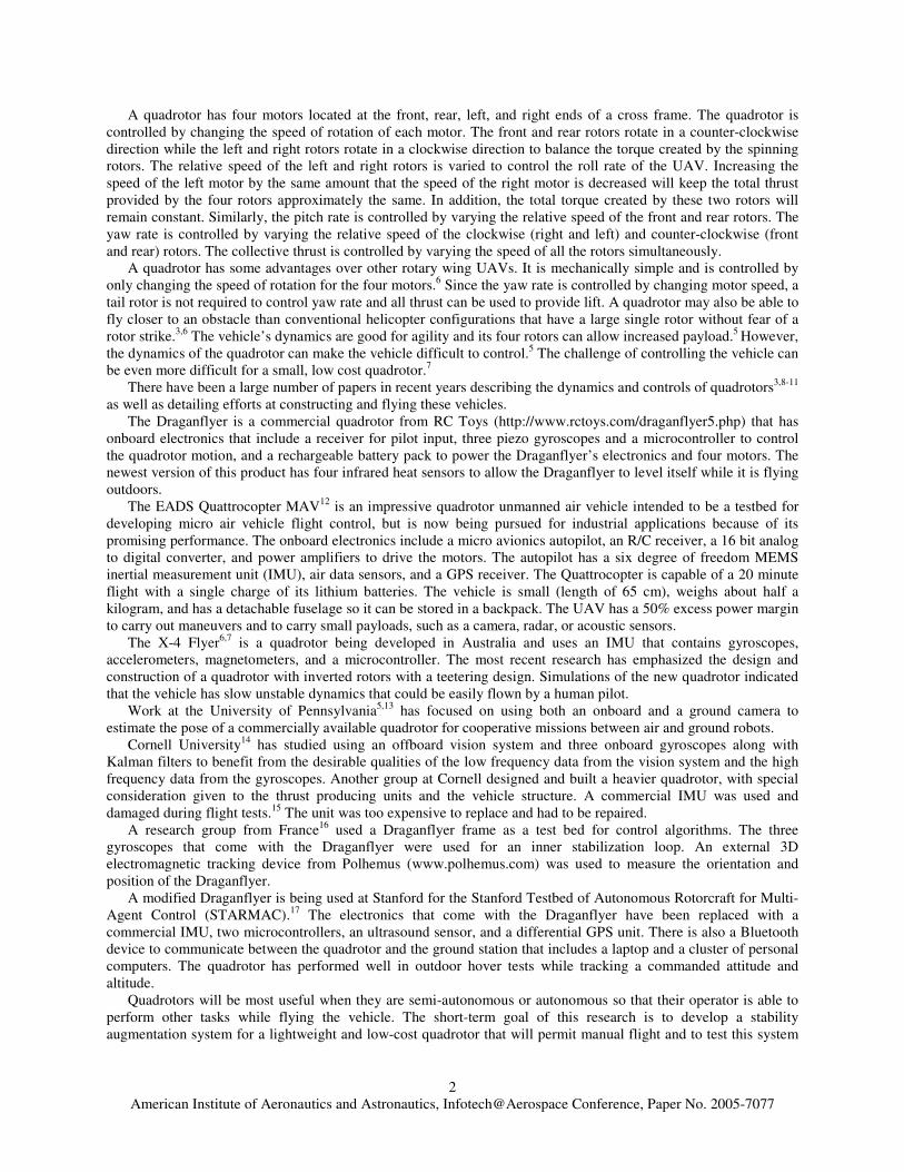
The CCS C compiler and Embedded C Language Development Kit (CCS Inc., http://www.ccsinfo.com/picc.shtml) with its In Circuit Debugger / Programming Unit (ICD-U40) was used to program the PIC 18F8720 chip. The development board is 2.5” by 4” and weighs 1.6 ounces (Figure 1). In addition to the PIC microcontroller, this circuit board has a header for accessing the microcontroller input/output pins, two serial ports with built-in buffering, a connector for the ICD, and other hardware including a voltage regulator and an oscillator crystal. To aid with programming and debugging, the board also has three LEDs, a potentiometer, and a push button switch. The In Circuit Debugger connects the PIC development board and a PC through a USB connection and allows program variable values to be watched, statements to be printed to the computer monitor, a break point to be inserted into the program, and programs to be stepped through line by line.
Figure 1. PIC development board. The PIC microcontroller is labeled “18F8720.”
American Institute of Aeronautics and Astronautics, Infotech@Aerospace Conference, Paper No. 2005-7077
4
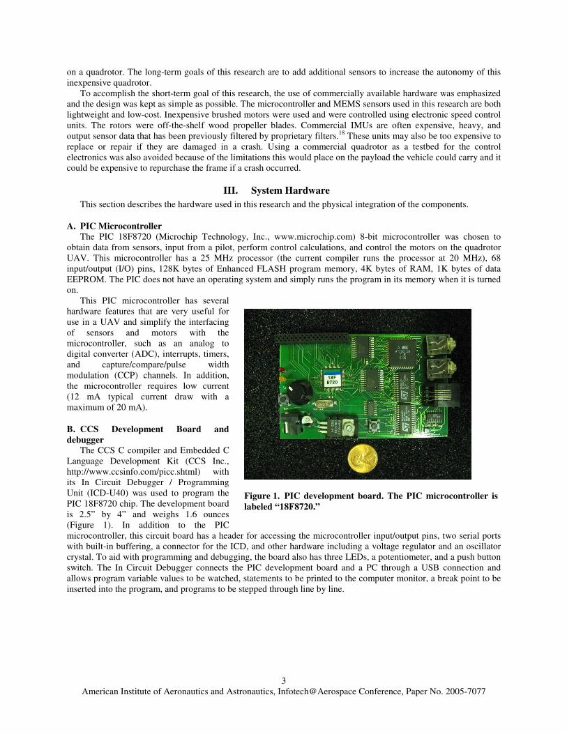
C. MEMS Sensors Two MEMS (Micro-Electro-Mechanical Systems)
sensors, a gyroscope and an accelerometer, were interfaced with the PIC microcontroller. A single chip rate gyro evaluation board (ADXRS150EB Analog Devices, Inc., www.analog.com) was used to measure angular velocity. The evaluation board, shown in Fig. 2 weighs three grams and is about 1” long by 0.5” wide. The sensor is capable of measuring +/-150 degrees/second of angular velocity and includes some signal conditioning electronics to help preserve the signal in noisy environments. The bandwidth of the evaluation board is fixed and set at 40 Hz. The chip produces an analog voltage output that is proportional to the angular velocity about the axis normal to the top surface of the gyroscope package
A dual-axis accelerometer evaluation board from Analog Devices, Inc. (ADXL210EB) was also interfaced with the PIC microcontroller. The accelerometer is capable of sensing accelerations of +/- 10 g’s in two perpendicular axes. The sensor chip produces a digital pulse proportional to its acceleration along two axes by using a duty cycle modulator that is included as part of the sensor chip.
Both sensors are available in smaller surface mount packages.
D. R/C transmitter and receiver An R/C transmitter and receiver were used to send input from the pilot to the PIC microcontroller on the
quadrotor. The transmitter and receiver are capable of communicating six channels of pilot input (Futaba model 6EXA, http://www.futaba-rc.com/radios/index.html).
E. Serial SSC Board The Mini SSCTM II (Scott Edwards Electronics, Inc, http://www.seetron.com/ssc.htm) is a serial servo controller
that can control multiple servo motors through serial communication. The SSC circuit board is 1.4” by 2.1” and weighs 0.6 oz. The board contains a PIC microcontroller, eight servo connectors, and connectors for supplying power to the microcontroller and for receiving serial communication. The board was configured for serial communication at a baud rate of 9600. The power requirements for the PIC microcontroller on the SSC board are 7–15V and 10 milliamps (mA).
The SSC board must receive a specific three byte sequence of serial data to control a servo motor. The first byte, called a sync byte, must be set to 255 and tells the SSC that a three byte servo command sequence has started. The second byte indicates the servo motor to which the current three byte sequence is being sent (the motor numbers can range from 0 to 254). The third byte is the desired position of the servo motor, which can also range from 0 to 254. The numbers sent to the SSC board must be sent as individual byte values, not the text representation of these numbers.
F. Power System: Batteries, motors, propellers, gears, electric speed controllers A combination of batteries, electric motors, and propellers was chosen to meet the desired requirements for flight
length, aircraft weight, and thrust production. A flight duration of 15 minutes, a time considered adequate to perform a worthwhile mission, was required. A thrust-to-weight ratio of 1.5–2:1 was deemed high enough to lift the quadrotor and provide sufficient control authority. A lightweight rechargeable battery that had a capacity large enough to allow the desired flight endurance and could provide high amounts of current for the motors was needed to provide power to the motors and the electronics (SSC board, PIC microcontroller, R/C receiver, and sensors).
The software program MotoCalc (version 7.09) from Capable Computing, Inc. (http://www.motocalc.com) was used to choose the components for the quadrotor’s power system. A rechargeable lithium polymer battery from Thunder Power met all of the requirements for the battery and was selected for use on the quadrotor. The battery has 3 cells for a total voltage of 11.1 volts, has a capacity of 2100 mAh, and weighs 5.1 oz. It can sustain a continuous
Figure 2. The two MEMS sensors are shown. The gyroscope is on the left and the accelerometer is on the right.
American Institute of Aeronautics and Astronautics, Infotech@Aerospace Conference, Paper No. 2005-7077
5
discharge of 21–25 Amps and a burst (momentary) discharge of 33 Amps. The motors and gearboxes used for the quadrotor are sold as a single unit by Grand Wing Servo (http://www.gwsus.com). The GW/EPS-100C-DS/BB power system, with a gear ratio of 6.60:1 was chosen. Each power system weighs 2 ounces. Two counterclockwise and two clockwise wood propellers from Zinger Propeller were used in the quadrotor. The propellers have diameters of 14 inches and pitches of 6 inches. Propellers with the combination of large diameter and small pitch were found to provide high static thrust, which is very important for the hovering maneuvers that the quadrotor will perform.
The Astro 217D electric speed controller (ESC) from AstroFlight, Inc. (www.astroflight.com) was used to convert the low current control signal from the SSC to a voltage and current capable of driving a motor. There is a safety feature on this speed controller that prevents the controller from activating until it receives a signal from the SSC board corresponding to the shortest pulse (1 ms high) for a duration of one second.
Simulations performed with Motocalc using this combination of battery, motor, gearbox, and propellers predicted that the requirements for length of flight and thrust-to-weight ratio would be satisfied. At full power, a thrust of 49 ounces was predicted. The total weight of the quadrotor with the parts used in the simulation was estimated to be 32 ounces. Therefore, at full power, the thrust-to-weight ratio was predicted to be about 1.5:1 and the flight time was estimated to be about 10 minutes. In addition, the current being drawn from the battery at full power was estimated to be 12.5 amps, which is within the specifications of the battery pack. The flight time at full power is less than the desired length, but when the power supplied to the motors is decreased to generate only the thrust needed to hover (32 ounces), the estimated flight time is increased to about 19 minutes.
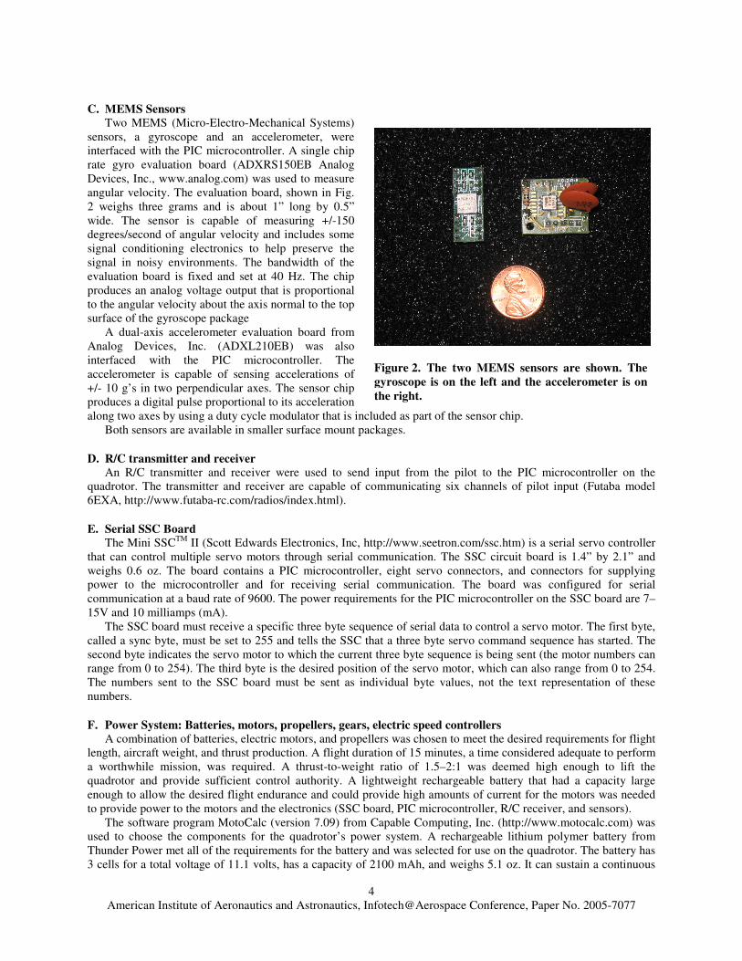
G. Test System A two-rotor test system, shown in Fig. 3, has been
developed to test the electronics and to implement a pilot-in-the-loop control law. Two motor/rotor power systems were mounted on both ends of a pivot that is constrained to rotate in one degree of freedom at its midpoint. Pilot input from the R/C transmitter and receiver was converted into the desired angular velocity of the system and a desired thrust. The gyroscope described above was used to measure angular velocity.
An onboard flight data recorder from Eagle Tree Systems (http://www.eagletreesystems.com.) was used to record pilot inputs (throttle and angular rate) during tests using the two rotor test set system. The data recorder can be used to monitor altitude, airspeed, battery level, and four channels of pilot controls. The flight data recorder is both lightweight and small: it weighs less than 3 ounces and its dimensions are 3.15” by 1.57” by 0.67”. To record these pilot inputs, “Y” cables must be installed between the radio receiver and the PIC microcontroller to allow the pilot input to reach both the microcontroller and the flight data recorder.
Figure 3. The two rotor test system used to test the electronics.
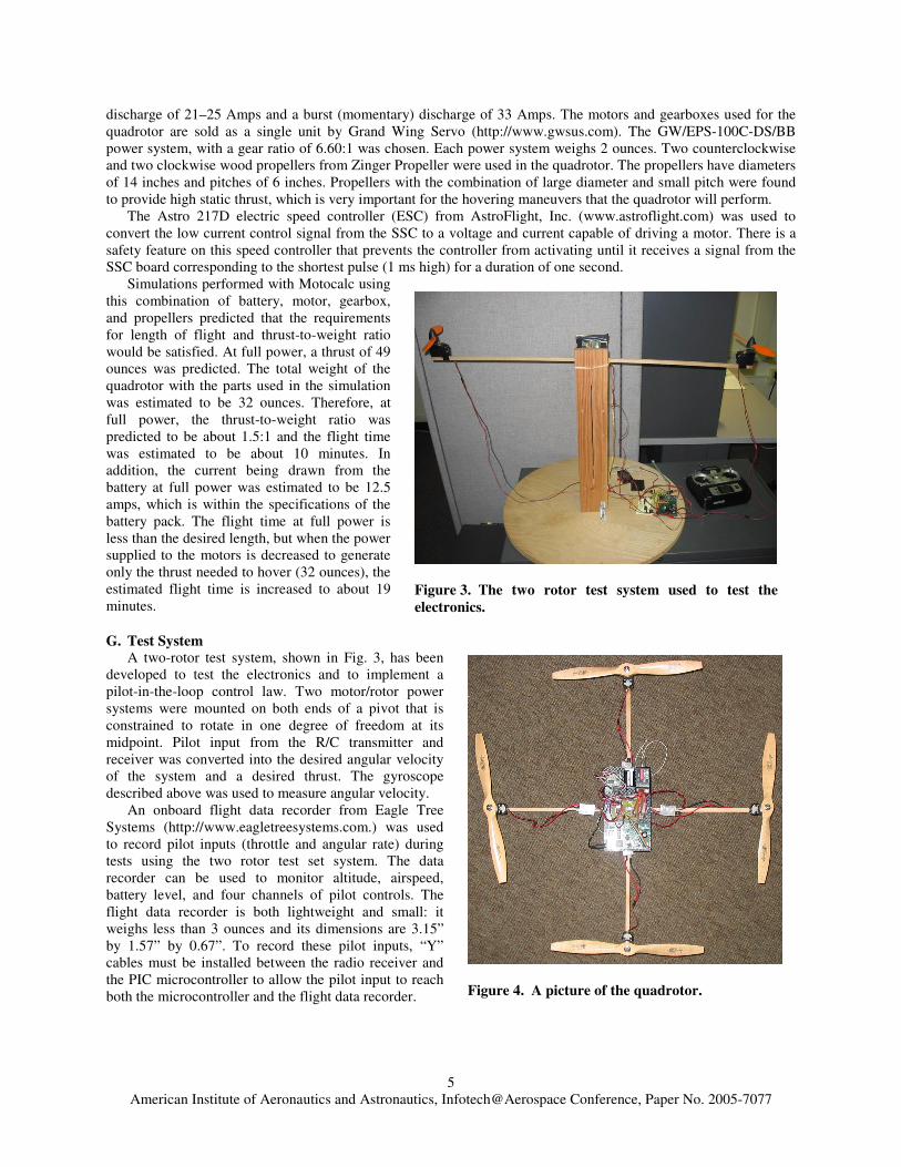
Figure 4. A picture of the quadrotor.
American Institute of Aeronautics and Astronautics, Infotech@Aerospace Conference, Paper No. 2005-7077
6
H. Quadrotor Frame The main goals when
designing and building the quadrotor frame were to create a frame that was lightweight, strong enough to survive rough landings, and simple enough to rebuild in case of damage sustained during landings. The frame is made of two pieces of 3/8 inch square spruce. A notch was cut in the middle of each piece and the pieces were attached with epoxy to form a cross. To attach the motors to the quadrotor frame, additional pieces of the 3/8 inch square spruce were attached to each of the four ends of the frame with epoxy. To help protect the quadrotor frame during landings, small two inch Styrofoam balls were attached to the bottom of each of the four spruce pieces used for mounting the motors. Lightweight, strong carbon fiber sheets from The Robot Marketplace (http://www.robotmarketplace.com), half inch thick foam rubber, and Dual LockTM fastener from 3M were used to mount the electronics to the quadrotor frame while isolating the sensors from vibrations in the frame. The battery pack was attached to the bottom of the frame using the Dual LockTM fastener. The completed quadrotor is shown in Fig. 4.
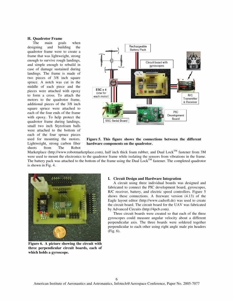
I. Circuit Design and Hardware Integration A circuit using three individual boards was designed and
fabricated to connect the PIC development board, gyroscopes, R/C receiver, battery, and electric speed controllers. Figure 5 shows these connections. A freeware version (4.13) of the Eagle layout editor (http://www.cadsoft.de) was used to create the circuit board. The circuit board for the UAV was fabricated by Advanced Circuits (http://4pcb.com).
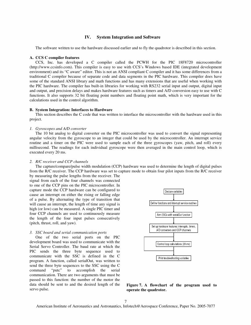
Three circuit boards were created so that each of the three gyroscopes could measure angular velocity about a different perpendicular axis. The three boards were soldered together perpendicular to each other using right angle male pin headers (Fig. 6).
Figure 6. A picture showing the circuit with three perpendicular circuit boards, each of which holds a gyroscope.
Figure 5. This figure shows the connections between the different hardware components on the quadrotor.
American Institute of Aeronautics and Astronautics, Infotech@Aerospace Conference, Paper No. 2005-7077
7
IV. System Integration and Software The software written to use the hardware discussed earlier and to fly the quadrotor is described in this section.
A. CCS C compiler features CCS, Inc. has developed a C compiler called the PCWH for the PIC 18F8720 microcontroller
(http://www.ccsinfo.com). This compiler is easy to use with CCS’s Windows based IDE (integrated development environment) and its “C aware” editor. This is not an ANSI compliant C compiler and it has some differences from a traditional C compiler because of separate code and data segments in the PIC hardware. This compiler does have some of the standard ANSI library and math functions and has many extensions that are useful when working with the PIC hardware. The compiler has built-in libraries for working with RS232 serial input and output, digital input and output, and precision delays and makes hardware features such as timers and A/D conversion easy to use with C functions. It also supports 32 bit floating point numbers and floating point math, which is very important for the calculations used in the control algorithm.
B. System Integration: Interfaces to Hardware This section describes the C code that was written to interface the microcontroller with the hardware used in this
project.
1. Gyroscopes and A/D converter The 10 bit analog to digital converter on the PIC microcontroller was used to convert the signal representing
angular velocity from the gyroscope to an integer that could be used by the microcontroller. An interrupt service routine and a timer on the PIC were used to sample each of the three gyroscopes (yaw, pitch, and roll) every millisecond. The readings for each individual gyroscope were then averaged in the main control loop, which is executed every 20 ms.
2. R/C receiver and CCP channels
The capture/compare/pulse width modulation (CCP) hardware was used to determine the length of digital pulses from the R/C receiver. The CCP hardware was set to capture mode to obtain four pilot inputs from the R/C receiver by measuring the pulse lengths from the receiver. The signal from each of the four channels was connected to one of the CCP pins on the PIC microcontroller. In capture mode the CCP hardware can be configured to cause an interrupt on either the rising or falling edge of a pulse. By alternating the type of transition that will cause an interrupt, the length of time any signal is high (or low) can be measured. A single PIC timer and four CCP channels are used to continuously measure the length of the four input pulses consecutively (pitch, thrust, roll, and yaw).
3. SSC board and serial communication ports
One of the two serial ports on the PIC development board was used to communicate with the Serial Servo Controller. The baud rate at which the PIC sends the three byte sequence used to communicate with the SSC is defined in the C program. A function, called serialOut, was written to send the three byte sequences to the SSC using the C command “putc” to accomplish the serial communication. There are two arguments that must be passed to this function: the number of the motor the data should be sent to and the desired length of the servo pulse.
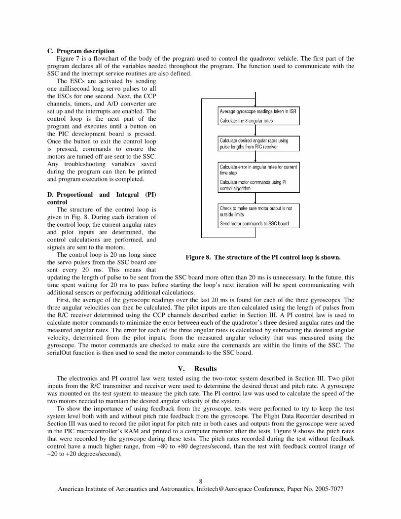
Figure 7. A flowchart of the program used to operate the quadrotor.
American Institute of Aeronautics and Astronautics, Infotech@Aerospace Conference, Paper No. 2005-7077
8
C. Program description Figure 7 is a flowchart of the body of the program used to control the quadrotor vehicle. The first part of the
program declares all of the variables needed throughout the program. The function used to communicate with the SSC and the interrupt service routines are also defined.
The ESCs are activated by sending one millisecond long servo pulses to all the ESCs for one second. Next, the CCP channels, timers, and A/D converter are set up and the interrupts are enabled. The control loop is the next part of the program and executes until a button on the PIC development board is pressed. Once the button to exit the control loop is pressed, commands to ensure the motors are turned off are sent to the SSC. Any troubleshooting variables saved during the program can then be printed and program execution is completed.
D. Proportional and Integral (PI) control
The structure of the control loop is given in Fig. 8. During each iteration of the control loop, the current angular rates and pilot inputs are determined, the control calculations are performed, and signals are sent to the motors.
The control loop is 20 ms long since the servo pulses from the SSC board are sent every 20 ms. This means that updating the length of pulse to be sent from the SSC board more often than 20 ms is unnecessary. In the future, this time spent waiting for 20 ms to pass before starting the loop’s next iteration will be spent communicating with additional sensors or performing additional calculations.
First, the average of the gyroscope readings over the last 20 ms is found for each of the three gyroscopes. The three angular velocities can then be calculated. The pilot inputs are then calculated using the length of pulses from the R/C receiver determined using the CCP channels described earlier in Section III. A PI control law is used to calculate motor commands to minimize the error between each of the quadrotor’s three desired angular rates and the measured angular rates. The error for each of the three angular rates is calculated by subtracting the desired angular velocity, determined from the pilot inputs, from the measured angular velocity that was measured using the gyroscope. The motor commands are checked to make sure the commands are within the limits of the SSC. The serialOut function is then used to send the motor commands to the SSC board.
V. Results The electronics and PI control law were tested using the two-rotor system described in Section III. Two pilot
inputs from the R/C transmitter and receiver were used to determine the desired thrust and pitch rate. A gyroscope was mounted on the test system to measure the pitch rate. The PI control law was used to calculate the speed of the two motors needed to maintain the desired angular velocity of the system.
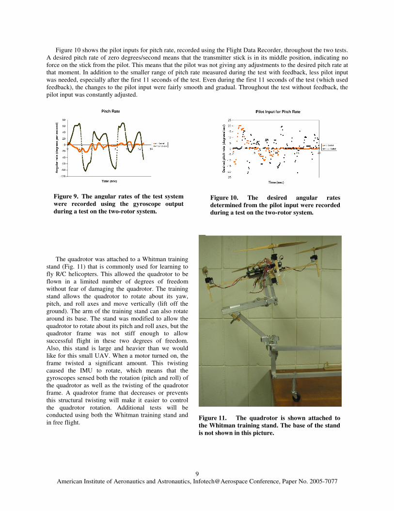
To show the importance of using feedback from the gyroscope, tests were performed to try to keep the test system level both with and without pitch rate feedback from the gyroscope. The Flight Data Recorder described in Section III was used to record the pilot input for pitch rate in both cases and outputs from the gyroscope were saved in the PIC microcontroller’s RAM and printed to a computer monitor after the tests. Figure 9 shows the pitch rates that were recorded by the gyroscope during these tests. The pitch rates recorded during the test without feedback control have a much higher range, from −80 to +80 degrees/second, than the test with feedback control (range of −20 to +20 degrees/second).
Figure 8. The structure of the PI control loop is shown.
American Institute of Aeronautics and Astronautics, Infotech@Aerospace Conference, Paper No. 2005-7077
9
Figure 9. The angular rates of the test system were recorded using the gyroscope output during a test on the two-rotor system.
Figure 11. The quadrotor is shown attached to the Whitman training stand. The base of the stand is not shown in this picture.
Figure 10. The desired angular rates determined from the pilot input were recorded during a test on the two-rotor system.
Figure 10 shows the pilot inputs for pitch rate, recorded using the Flight Data Recorder, throughout the two tests. A desired pitch rate of zero degrees/second means that the transmitter stick is in its middle position, indicating no force on the stick from the pilot. This means that the pilot was not giving any adjustments to the desired pitch rate at that moment. In addition to the smaller range of pitch rate measured during the test with feedback, less pilot input was needed, especially after the first 11 seconds of the test. Even during the first 11 seconds of the test (which used feedback), the changes to the pilot input were fairly smooth and gradual. Throughout the test without feedback, the pilot input was constantly adjusted.
The quadrotor was attached to a Whitman training
stand (Fig. 11) that is commonly used for learning to fly R/C helicopters. This allowed the quadrotor to be flown in a limited number of degrees of freedom without fear of damaging the quadrotor. The training stand allows the quadrotor to rotate about its yaw, pitch, and roll axes and move vertically (lift off the ground). The arm of the training stand can also rotate around its base. The stand was modified to allow the quadrotor to rotate about its pitch and roll axes, but the quadrotor frame was not stiff enough to allow successful flight in these two degrees of freedom. Also, this stand is large and heavier than we would like for this small UAV. When a motor turned on, the frame twisted a significant amount. This twisting caused the IMU to rotate, which means that the gyroscopes sensed both the rotation (pitch and roll) of the quadrotor as well as the twisting of the quadrotor frame. A quadrotor frame that decreases or prevents this structural twisting will make it easier to control the quadrotor rotation. Additional tests will be conducted using both the Whitman training stand and in free flight.
American Institute of Aeronautics and Astronautics, Infotech@Aerospace Conference, Paper No. 2005-7077
10
VI. Conclusion A lightweight quadrotor system has been designed with an emphasis on using inexpensive COTS components.
The components have been integrated and pilot-in-the-loop PI control has been successfully implemented on a single degree of freedom test system using these components. The electronics have been used to develop a stability augmentation system that will allow manual flight of the quadrotor. The quadrotor was placed on a training stand with two degrees of freedom, but the flexibility of the quadrotor frame prevented successful flight. More flights will be conducted in the near future.
This research has demonstrated that low-cost components can be used to create a control system that will allow manual flight for a quadrotor. These electronics have been developed so that they can be easily integrated with additional sensors such as cameras, sonar, and optic flow sensors to increase the level of quadrotor autonomy. In addition, a control algorithm more sophisticated than the current PI control can be used.
Acknowledgments The support of the Penn State Rotorcraft Center of Excellence, the National Defense Science and Engineering
Graduate Fellowship program, and the National Science Foundation Graduate Research Fellowship Program are gratefully acknowledged.
References
1“Unmanned Air Vehicles Roadmap, 2002-2027,” Office of the Secretary of Defense, 2002. 2“Unmanned Air Systems Roadmap, 2005-2030,” Office of the Secretary of Defense, 2005. 3McKerrow, P., “Modelling the Draganflyer four-rotor helicopter,” Proceedings of the 2004 IEEE International Conference
on Robotics and Automation, New Orleans, LA , 2004, pp. 3596-3601. 4Wu, H., Zhou, Z., Sun, D., “Autonomous Hovering Control and Test for Micro Air Vehicle,” Proceedings of IEEE
International Conference on Robotics and Automation, Taipei, Taiwan, 2003, pp. 528-533. 5Altug, E., Ostrowski, J.P., Mahony, R., “Control of a quadrotor helicopter using visual feedback,” Proceedings of the IEEE
International Conference on Robotics and Automation, Washington, D.C., 2002, pp 72–77. 6Pounds, P., Mahony, R., Gresham, J., Corke, P., Roberts, J., “Towards Dynamically-Favourable Quad-Rotor Aerial Robots,”
Proceedings of the 2004 Australasian Conference on Robotics and Automation, Canberra, Australia, 2004. 7Pounds, P., Mahony, R., Hynes, P., Roberts, J., “Design of a Four-Rotor Aerial Robot,” Proceedings of the 2002
Australasian Conference on Robotics and Automation, Auckland, New Zealand, 2002, pp. 145-150. 8Hamel, T., Mahony, R., Lozano, R., Ostrowski, J., “Dynamic Modelling and Configuration Stabilization for an X4 Flyer,”
IFAC 15th Triennial World Congress, Barcelona, Spain, 2002. 9Hamel, T., Mahony, R., Chriette, A., “Visual servo trajectory tracking for a four rotor VTOL aerial vehicle,” Proceedings of
the IEEE International Conference on Robotics and Automation, Washington, D.C., 2002, pp. 2781-2786. 10�berg, M., “4xFanSaucer,” M.S. Thesis, KTH Signals Sensors and Systems, Stockholm, Sweden, 2004. 11M. Chen and M. Huzmezan , “A combined MBPC/2 DOF H� controller for a Quad Rotor UAV,” AIAA Atmospheric Flight
Mechanics Conference and Exhibit, Austin, Texas, 2003. 12Arning, R.K., Sassen, S., “Flight Control of Micro Aerial Vehicles,” AIAA Guidance, Navigation, and Control Conference,
Providence, Rhode Island, 2004. 13Altug, E., Ostrowski, J.P., Taylor, C.J., “Quadrotor control using dual camera visual feedback,” Proceedings of IEEE
International Conference on Robotics and Automation, Taipei, Taiwan, 2003, pp. 4294–4299. 14Earl, M.G., D’Andrea, R., “Real-Time Attitude Estimation Techniques Applied to a Four Rotor Helicopter,” Proceeding of
the 43rd IEEE Conference on Decision and Control, Atlantis, Paradise Island, Bahamas, 2004, pp.3956-3961. 15Nice, E.B., “Design of a Four Rotor Hovering Vehicle,” M.S. Thesis, Cornell University, Ithaca, NY, 2004. 16Castillo, P., Dzul, A., Lozano, R., “Real-Time Stabilization and Tracking of a Four-Rotor Mini Rotorcraft,” IEEE
Transactions on Control Systems Technology, Vol. 12, No. 4, July 2004. 17Hoffmann, G., Rajnarayan, D.G., Waslander, S.L., Dostal, D., Jang, J.S., Tomlin, C.J., “The Stanford Testbed of
Autonomous Rotorcraft for Multi Agent Control (STARMAC),” Proceedings of the 23rd Digital Avionics Systems Conference, Salt Lake City, Utah, November, 2004.
18Roberts, J.M., Corke, P.I., Buskey, G., “Design of a Four-Rotor Aerial Robot,” Proceedings of the 2002 Australasian Conference on Robotics and Automation, Auckland, New Zealand, 2002, pp. 71-76.