a small fission power system for nasa planetary science
TRANSCRIPT

Lee MasonGlenn Research Center, Cleveland, Ohio
John Casani, John Elliott, Jean-Pierre Fleurial, Duncan MacPherson, and Bill NesmithJet Propulsion Laboratory, Pasadena, California
Michael HoutsMarshall Space Flight Center, Huntsville, Alabama
Ryan BechtelDepartment of Energy, Germantown, Maryland
Jim WernerIdaho National Laboratory, Idaho Falls, Idaho
Rick Kapernick and David PostonLos Alamos National Laboratory, Los Alamos, New Mexico
Arthur Lou QuallsOak Ridge National Laboratory, Oak Ridge, Tennessee
Ron Lipinski and Ross RadelSandia National Laboratories, Albuquerque, New Mexico
Sterling BaileyConsultant, Grass Valley, California
Abraham WeitzbergConsultant, Woodland Hills, California
A Small Fission Power System for NASAPlanetary Science Missions
NASA/TM—2011-217099
December 2011
NETS–2011–3318

NASA STI Program . . . in Profi le
Since its founding, NASA has been dedicated to the advancement of aeronautics and space science. The NASA Scientifi c and Technical Information (STI) program plays a key part in helping NASA maintain this important role.
The NASA STI Program operates under the auspices of the Agency Chief Information Offi cer. It collects, organizes, provides for archiving, and disseminates NASA’s STI. The NASA STI program provides access to the NASA Aeronautics and Space Database and its public interface, the NASA Technical Reports Server, thus providing one of the largest collections of aeronautical and space science STI in the world. Results are published in both non-NASA channels and by NASA in the NASA STI Report Series, which includes the following report types: • TECHNICAL PUBLICATION. Reports of
completed research or a major signifi cant phase of research that present the results of NASA programs and include extensive data or theoretical analysis. Includes compilations of signifi cant scientifi c and technical data and information deemed to be of continuing reference value. NASA counterpart of peer-reviewed formal professional papers but has less stringent limitations on manuscript length and extent of graphic presentations.
• TECHNICAL MEMORANDUM. Scientifi c
and technical fi ndings that are preliminary or of specialized interest, e.g., quick release reports, working papers, and bibliographies that contain minimal annotation. Does not contain extensive analysis.
• CONTRACTOR REPORT. Scientifi c and
technical fi ndings by NASA-sponsored contractors and grantees.
• CONFERENCE PUBLICATION. Collected papers from scientifi c and technical conferences, symposia, seminars, or other meetings sponsored or cosponsored by NASA.
• SPECIAL PUBLICATION. Scientifi c,
technical, or historical information from NASA programs, projects, and missions, often concerned with subjects having substantial public interest.
• TECHNICAL TRANSLATION. English-
language translations of foreign scientifi c and technical material pertinent to NASA’s mission.
Specialized services also include creating custom thesauri, building customized databases, organizing and publishing research results.
For more information about the NASA STI program, see the following:
• Access the NASA STI program home page at http://www.sti.nasa.gov
• E-mail your question via the Internet to help@
sti.nasa.gov • Fax your question to the NASA STI Help Desk
at 443–757–5803 • Telephone the NASA STI Help Desk at 443–757–5802 • Write to:
NASA Center for AeroSpace Information (CASI) 7115 Standard Drive Hanover, MD 21076–1320

Lee MasonGlenn Research Center, Cleveland, Ohio
John Casani, John Elliott, Jean-Pierre Fleurial, Duncan MacPherson, and Bill NesmithJet Propulsion Laboratory, Pasadena, California
Michael HoutsMarshall Space Flight Center, Huntsville, Alabama
Ryan BechtelDepartment of Energy, Germantown, Maryland
Jim WernerIdaho National Laboratory, Idaho Falls, Idaho
Rick Kapernick and David PostonLos Alamos National Laboratory, Los Alamos, New Mexico
Arthur Lou QuallsOak Ridge National Laboratory, Oak Ridge, Tennessee
Ron Lipinski and Ross RadelSandia National Laboratories, Albuquerque, New Mexico
Sterling BaileyConsultant, Grass Valley, California
Abraham WeitzbergConsultant, Woodland Hills, California
A Small Fission Power System for NASAPlanetary Science Missions
NASA/TM—2011-217099
December 2011
NETS–2011–3318
National Aeronautics andSpace Administration
Glenn Research CenterCleveland, Ohio 44135
Prepared for theNuclear and Emerging Technologies for Space (NETS-2011)cosponsored by the ANS Aerospace Nuclear Science and Technology Division, the ANS Trinity Section,and the AIAAAlbuquerque, New Mexico, February 7–10, 2011

Acknowledgments
This work was performed for the Decadal Survey Giant Planets Panel (GPP) in coordination with the National Aeronautics and Space Administration (NASA) Science Mission Directorate. The authors wish to acknowledge the contributions and support of the study sponsors including Heidi Hammel (GPP Chairperson) and Len Dudzinski (Planetary Science Division). The study was coordinated through the NASA Glenn Research Center Radioisotope Power System Program Offi ce managed by John Hamley. The quality results would not have been possible without the involvement of Scott Harlow from Department of Energy (DOE) Headquarters who assembled the DOE team, coordinated their participation, and reviewed the fi nal products.
Available from
NASA Center for Aerospace Information7115 Standard DriveHanover, MD 21076–1320
National Technical Information Service5301 Shawnee Road
Alexandria, VA 22312
Available electronically at http://www.sti.nasa.gov
Trade names and trademarks are used in this report for identifi cation only. Their usage does not constitute an offi cial endorsement, either expressed or implied, by the National Aeronautics and
Space Administration.
Level of Review: This material has been technically reviewed by technical management.
This report contains preliminary fi ndings, subject to revision as analysis proceeds.

NASA/TM—2011-217099 1
A Small Fission Power System for NASA Planetary Science Missions
Lee Mason National Aeronautics and Space Administration
Glenn Research Center Cleveland, Ohio 44135
John Casani, John Elliott, Jean-Pierre Fleurial, Duncan MacPherson, and Bill Nesmith
National Aeronautics and Space Administration Jet Propulsion Laboratory
Pasadena, California 91109
Michael Houts National Aeronautics and Space Administration
Marshall Space Flight Center Huntsville, Alabama 35812
Ryan Bechtel
Department of Energy Germantown, Maryland 20874
Jim Werner
Idaho National Laboratory Idaho Falls, Idaho 83415
Rick Kapernick and David Poston Los Alamos National Laboratory Los Alamos, New Mexico 87545
Arthur Lou Qualls
Oak Ridge National Laboratory Oak Ridge, Tennessee 37831
Ron Lipinski and Ross Radel Sandia National Laboratories
Albuquerque, New Mexico 87185
Sterling Bailey Consultant
Grass Valley, California 95945
Abraham Weitzberg Consultant
Woodland Hills, California 91367

NASA/TM—2011-217099 2
Abstract
In March 2010, the Decadal Survey Giant Planets Panel (GPP) requested a short-turnaround study to evaluate the feasibility of a small Fission Power System (FPS) for future unspecified National Aeronautics and Space Administration (NASA) science missions. FPS technology was considered a potential option for power levels that might not be achievable with radioisotope power systems. A study plan was generated and a joint NASA and Department of Energy (DOE) study team was formed. The team developed a set of notional requirements that included 1-kW electrical output, 15-year design life, and 2020 launch availability. After completing a short round of concept screening studies, the team selected a single concept for concentrated study and analysis. The selected concept is a solid block uranium-molybdenum reactor core with heat pipe cooling and distributed thermoelectric power converters directly coupled to aluminum radiator fins. This paper presents the preliminary configuration, mass summary, and proposed development program.
Nomenclature
CBE current best estimate CD Concept Development DOE Department of Energy FFTF Fast Flux Test Facility FPS Fission Power System FSP Fission Surface Power GPHS general-purpose heat source GPP Giant Planets Panel GRC Glenn Research Center HEU highly enriched uranium HGA high-gain antenna INL Idaho National Laboratory JPL Jet Propulsion Laboratory LA Launch Approval LANL Los Alamos National Laboratory MSFC Marshall Space Flight Center NASA National Aeronautics and Space Administration NEPA National Environmental Policy Act ORNL Oak Ridge National Laboratory RF radiofrequency RTG radioisotope thermoelectric generator SNL Sandia National Laboratories
Study Overview
The small Fission Power System (FPS) study was initiated in March 2010 following a request from the Decadal Survey Giant Planets Panel (GPP) and the NASA Science Mission Directorate. A 6-week study was commissioned to evaluate the feasibility of a 1-kWe-class FPS for future NASA science missions. The study was assigned to Glenn Research Center (GRC) and a study team was formed that included participants from the Jet Propulsion Laboratory (JPL); Marshall Space Flight Center (MSFC); Department of Energy (DOE) Headquarters; and the DOE National Laboratories at Idaho (INL), Los

NASA/TM—2011-217099 3
Alamos (LANL), Oak Ridge (ORNL), and Sandia (SNL). The study scope included a review of component technologies and concept options, a down-selection to a single concept for concentrated study, and a preliminary assessment of the system performance, configuration, mass, verification strategy, and development schedule. The team was also asked to consider the extensibility of the concept to higher power levels. The effort culminated in a presentation to the GPP on April 16, 2010, and a narrative report completed in mid-May.
Ground Rules and Assumptions
At the outset of the study, a set of notional requirements was developed and concurred upon by the study sponsors. The requirements were broadly defined to cover a range of potential Giant Planet science missions. An over-arching requirement was that the FPS would be safe for launch and operations, including assured subcriticality prior to commanded reactor startup. The major parameters that affect technology selection are power level, lifetime, and launch date. For this study, these were chosen as 1-kWe continuous output, 15-year design life, and 2020 launch availability. Several spacecraft integration requirements were also adopted. These included the reactor-induced radiation dose (1.0×10¹¹ n/cm2 and 25 krad), payload envelope size (4.5 m diameter), and electrical bus voltage (28 Vdc). The radiation limits were selected to allow the use of commercially available electronics at the payload dose plane. To better accommodate the radiation dose limits, the payload was assumed to be located at a specified separation distance from the reactor within a defined cone angle. This geometry set the parameters required to determine the dimensions and mass of the radiation shielding.
In addition to the assumptions stated above, the study team agreed on several goals for the FPS. While no mass or volume metric was set, minimizing these parameters would make the system more attractive to potential missions. At the same time, the team judged that low cost and low risk (both developmental and operational) were even more important than mass. An additional goal was to minimize the system-related accommodations imposed on the spacecraft. These might include the need for control actions, operational constraints, additional power sources, or extension booms. Another key FPS goal expressed by the team and echoed in the study objectives was the potential for mission extensibility, especially as it relates to upward power scalability.
Technology Options
Since the advent of the nuclear age, researchers, engineers, and scientists have been exploring and testing many forms of nuclear fuels, structural materials, shielding materials, and design configurations. A wealth of knowledge and performance capabilities have been established and are available for consideration in design options. A listing of the various component technologies and design approaches that were considered in developing potential system concepts is provided in Table 1.
TABLE 1.—POTENTIAL TECHNOLOGY OPTIONS CONSIDERED
Category Options Reactor fuel Oxide (UO2), Metal (UMo, UZr), Nitride (UN), Carbide (UC), Cermet, UZrH Fuel form Pins, Plates, Block, Spheres Neutron spectrum Thermal, Epithermal, Fast Cladding/Structure Stainless Steel, Ni-Based Superalloy, Refractory Alloy Control materials Be, BeO (Neutron Reflecting), B4C (Neutron Absorbing) Mechanism Rods, Drums, Shutters, Sliders Heat transport Conduction, Heat Pipe, Pumped Liquid Metal, Gas Reactor heat transfer fluids Sodium, Potassium, NaK, Lithium, HeXe, CO2 Shield materials LiH, B4C, Tungsten, Depleted Uranium, Lead, Water, Polyethylene, Aluminum Power conversion Thermoelectric (SiGe, PbTe/TAGS, Skutterudites, Zintl/LaTe/SKD), Stirling,
Brayton (HeXe, CO2) , Rankine (Organic, Hg, K) Heat rejection Direct Radiation, Heat Pipes, Two-Phase Loops, Pumped Liquid Loop Radiator fluids Water, Ammonia, Fluorocarbons, Hydrocarbons Radiator materials Aluminum, Polymer Composites, Titanium

NASA/TM—2011-217099 4
Typical uranium fuel types range from oxides (i.e., UO2), the most commonly used form of fuel in terrestrial power reactors, to metal fuels (i.e., UMo and UZr), common to fast reactor technologies, to other chemical fuel forms that have specialized performance characteristics (e.g., nitride (UN), carbide (UC), cermet, and UZrH). These fuels have been evaluated from a mechanical/physical standpoint and performance tested in various forms (e.g., pins, plates, blocks, and microspheres) under expected nuclear irradiation conditions. Consequently, a number of fuel types and configurations could be considered for this space reactor application.
The U.S. experience with mixed oxide and metal fuels is substantial, comprising irradiation of over 50,000 oxide fuel rods and 130,000 metal fuel rods in the Experimental Breeder Reactor-II (EBR–II) and the Fast Flux Test Facility (FFTF) alone. Most types of fuel have been demonstrated capable of fuel utilization exceeding 10 percent fuel burnup. To varying degrees, life-limiting phenomena for all types have been identified and investigated. For this study there are no disqualifying safety-related fuel behaviors that would reduce the viability of any of the fuels for use. However, fuel density becomes a dominant factor when designing very small reactor systems. Likewise, reactor configurations utilizing different neutron spectra for maintaining nuclear criticality have been studied and well established. Nuclear reactor designs basically fall into three categories: 1) Thermal: fission neutrons are rapidly slowed down to thermal energy ranges before the next fission reaction occurs (e.g., water-moderated reactors), 2) Epithermal: neutrons lose most of their energy before next fission (e.g., graphite-moderated and gas-cooled reactors), and 3) Fast: neutrons are absorbed with minimal loss of energy prior to the next fission (e.g., sodium-cooled reactors). The most “neutron-efficient” reactors are thermal systems; however, the smallest, most lightweight reactors have fast spectra.
Most nuclear fuel cladding and structural materials are made of zirconium alloys and stainless steels. Nickel-based superalloys have also been extensively tested in the nuclear industry where higher temperatures and operating pressures are desired, and a variety of reactor system applications have been pursued. Refractory alloys have been explored and a large amount of data exists regarding performance of these materials under high-temperature and high-radiation environments, but their use would require additional development and fabrication investments.
Control of a nuclear reactor system is achieved by utilizing materials that reflect neutrons back into the core (e.g., water, graphite, beryllium (Be), or beryllium-oxide (BeO)) and materials that absorb neutrons (e.g., boron (B) and boron carbide (B4C)). For small lightweight reactors, Be or BeO are more suitable reflector materials, and B4C is more suitable for the neutron absorber. A variety of combinations of these two materials have been employed in test reactors as well as previous space designs. Typical control options include the use of rods (pins are inserted in the reactor), drums (a section of the drum surface has absorbing material and is located outside the reactor core), shutters (reflector or absorbing materials are arranged outside the reactor core and their position adjusted to either allow more neutron leakage or exposure to neutron absorbing material), or sliders (reflector or absorbing materials are arranged outside the reactor core and the materials are made to slide around the core to either allow more neutron leakage, reflection, or exposure to neutron absorbing material).
Reactor heat transport is typically accomplished by flowing a liquid or a gas through the core. Coolant options for this type of system include sodium (Na), potassium (K), NaK, lithium (Li), helium-xenon (HeXe), or carbon dioxide (CO2) as the heat transfer fluid. All reactors that transport heat from a reactor core using liquid or gas require a circulation pump or rely on gravity to induce circulation by convection. A novel approach of using heat pipes for primary heat transport has been investigated over the past 30 years and a significant amount of testing has been accomplished in both radiation and nonradiation test environments. However, a heat-pipe-cooled reactor has not yet been built or operated.
A large variety of shielding materials have also been developed and tested over the years. Effective shielding requires the use of a specific class of materials to reduce the radiation from neutrons using low-mass elements (e.g., hydrogen (H), Li, and B), and from beta and gamma radiation using higher mass elements (e.g., tungsten (W), depleted uranium (DU), and lead (Pb)). The shielding material selections are also influenced by other design requirements such as operating temperature, heat load, structural stability, and material compatibility.
NASA/TM—2011-217099 5
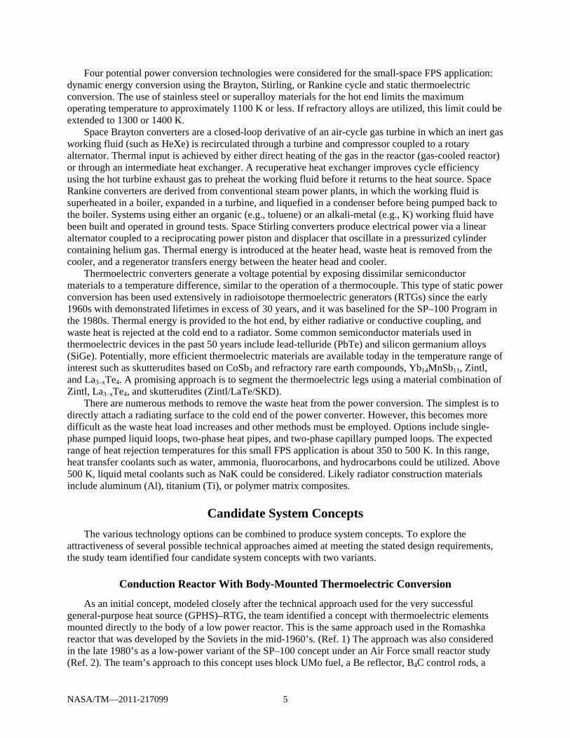
Four potential power conversion technologies were considered for the small-space FPS application: dynamic energy conversion using the Brayton, Stirling, or Rankine cycle and static thermoelectric conversion. The use of stainless steel or superalloy materials for the hot end limits the maximum operating temperature to approximately 1100 K or less. If refractory alloys are utilized, this limit could be extended to 1300 or 1400 K.
Space Brayton converters are a closed-loop derivative of an air-cycle gas turbine in which an inert gas working fluid (such as HeXe) is recirculated through a turbine and compressor coupled to a rotary alternator. Thermal input is achieved by either direct heating of the gas in the reactor (gas-cooled reactor) or through an intermediate heat exchanger. A recuperative heat exchanger improves cycle efficiency using the hot turbine exhaust gas to preheat the working fluid before it returns to the heat source. Space Rankine converters are derived from conventional steam power plants, in which the working fluid is superheated in a boiler, expanded in a turbine, and liquefied in a condenser before being pumped back to the boiler. Systems using either an organic (e.g., toluene) or an alkali-metal (e.g., K) working fluid have been built and operated in ground tests. Space Stirling converters produce electrical power via a linear alternator coupled to a reciprocating power piston and displacer that oscillate in a pressurized cylinder containing helium gas. Thermal energy is introduced at the heater head, waste heat is removed from the cooler, and a regenerator transfers energy between the heater head and cooler.
Thermoelectric converters generate a voltage potential by exposing dissimilar semiconductor materials to a temperature difference, similar to the operation of a thermocouple. This type of static power conversion has been used extensively in radioisotope thermoelectric generators (RTGs) since the early 1960s with demonstrated lifetimes in excess of 30 years, and it was baselined for the SP–100 Program in the 1980s. Thermal energy is provided to the hot end, by either radiative or conductive coupling, and waste heat is rejected at the cold end to a radiator. Some common semiconductor materials used in thermoelectric devices in the past 50 years include lead-telluride (PbTe) and silicon germanium alloys (SiGe). Potentially, more efficient thermoelectric materials are available today in the temperature range of interest such as skutterudites based on CoSb3 and refractory rare earth compounds, Yb14MnSb11, Zintl, and La3–xTe4. A promising approach is to segment the thermoelectric legs using a material combination of Zintl, La3–xTe4, and skutterudites (Zintl/LaTe/SKD).
There are numerous methods to remove the waste heat from the power conversion. The simplest is to directly attach a radiating surface to the cold end of the power converter. However, this becomes more difficult as the waste heat load increases and other methods must be employed. Options include single-phase pumped liquid loops, two-phase heat pipes, and two-phase capillary pumped loops. The expected range of heat rejection temperatures for this small FPS application is about 350 to 500 K. In this range, heat transfer coolants such as water, ammonia, fluorocarbons, and hydrocarbons could be utilized. Above 500 K, liquid metal coolants such as NaK could be considered. Likely radiator construction materials include aluminum (Al), titanium (Ti), or polymer matrix composites.
Candidate System Concepts
The various technology options can be combined to produce system concepts. To explore the attractiveness of several possible technical approaches aimed at meeting the stated design requirements, the study team identified four candidate system concepts with two variants.
Conduction Reactor With Body-Mounted Thermoelectric Conversion
As an initial concept, modeled closely after the technical approach used for the very successful general-purpose heat source (GPHS)–RTG, the team identified a concept with thermoelectric elements mounted directly to the body of a low power reactor. This is the same approach used in the Romashka reactor that was developed by the Soviets in the mid-1960’s. (Ref. 1) The approach was also considered in the late 1980’s as a low-power variant of the SP–100 concept under an Air Force small reactor study (Ref. 2). The team’s approach to this concept uses block UMo fuel, a Be reflector, B4C control rods, a
NASA/TM—2011-217099 6
superalloy structure, lithium hydride (LiH)/W shield, SiGe thermoelectric elements on the outside of a radial reflector, and a liquid-metal heat pipe radiator, with the entire system forward of shield and within the shield cone angle. To minimize the mass of the system, a very compact core was necessary, which limited the amount of reactor surface area for mounting the thermoelectrics. Also, because of the nuclear radiation from the reactor core, space reactor configurations necessarily have the spacecraft payload separated from the reactor by a tapered shield in the shape of a frustum of a cone, with the apex of the cone away from the payload. This arrangement severely limits the amount of radiator area that can be accommodated in front of the shield. Because of these constraints, it was estimated that the power level of this concept would be limited to about 0.5 kWe. Even with the use of alternate reflector configurations, or higher temperature core materials, the power level possible from this concept would remain substantially below the 1-kWe target.
Heat Pipe Reactor With Distributed Thermoelectric Conversion
This concept uses the same reactor and shield technologies as the conduction reactor concept, but uses in-core liquid-metal heat pipes to transport heat from the core through the shield to Zintl/LaTe/SKD thermoelectric elements distributed along the heat pipes and directly coupled to individual aluminum radiator fins at the thermoelectric cold end. Moving the power conversion and heat rejection components behind the shield eliminates the volume and area constraints that limited the conduction reactor concept. It also increased the radiation margin for the already radiation-hard thermoelectric materials. Although the Zintl/LaTe/SKD thermoelectric materials are less mature than the SiGe, their use yields improved efficiency at the lower temperature available at the heat pipe condenser. This concept was judged to be a good choice for a 1-kWe-class system.
Heat Pipe Reactor With Compact Thermoelectric Heat Exchangers or Stirling Power Conversion
This concept uses the same reactor, shield, and heat pipe technologies as described for the heat pipe reactor above, but replaces the distributed thermoelectric elements with Zintl/LaTe/SKD thermoelectric elements integrated into compact heat exchangers. Additionally, secondary water heat pipes are used to transfer waste heat from the cold end of the thermoelectrics to an aluminum radiator. This concept is more complex than the previous system, but would be scalable up to perhaps 5 kWe.
A variant of this concept uses the same reactor, shield, and heat pipe technologies, but replaces the compact thermoelectric heat exchangers with Stirling converters to increase power output. This concept is possibly more complex than the system with compact thermoelectric heat exchangers, but would be scalable up to about 10 kWe.
Pumped Liquid Metal Reactor With Compact Thermoelectric Heat Exchangers or Stirling Power Conversion
This concept uses the well-understood reactor and primary heat transport technologies from terrestrial fast reactors and the Fission Surface Power (FSP) concept, now being studied by NASA’s Exploration Systems Mission Directorate (Ref. 3). The reactor system utilizes UO2 fuel pins, a Be reflector, rotating Be/B4C control drums, stainless steel structure, a LiH/W shield, and a pumped NaK primary loop using a thermoelectric electromagnetic pump. The reactor system would provide heat to Zintl/LaTe/SKD thermoelectric elements in compact heat exchangers, rejecting heat through pumped NaK secondary loops to composite radiators. This concept was assessed to be too heavy for a 1-kWe-class system, but could be a viable option for 10 or 20 kWe.

NASA/TM—2011-217099 7
A variant of this concept uses all of the technologies of the FSP system including the same reactor technologies, but would use an annular linear induction pump to transport the NaK coolant to multiple Stirling converters. Waste heat would be rejected via pumped water secondary loops to water heat pipe radiators. While too heavy for the 1 kWe class, this concept is well suited for power levels from about 10 kWe up to perhaps 100 kWe.
Selected System Concept
The study team selected the heat pipe reactor with distributed thermoelectric conversion for concentrated study and analysis. The main factors leading to this selection were design simplicity, reasonable system mass, and low development risk.
The selected concept accomplishes the goals of minimizing the complexity of fission systems and making them competitive with radioisotope power systems on a mass basis. The compact nature of the block UMo core and BeO radial reflector allows the reactor diameter to be as small as practical while still meeting the neutronic and thermal power demands. This directly translates to lower shield mass since the reactor diameter dictates the footprint of the radiation shield. The use of LiH and W provides a mass-efficient material combination for meeting the radiation requirements at the spacecraft. The reactor control is simplified through the use of a single, core-centered control rod whose operation is only required during reactor startup. The use of heat pipes offers a straightforward primary heat transport approach using proven liquid-metal heat pipe technology. Further, the elimination of complex heat transport components, both at the reactor side and radiator side, contributes to reducing the total partcount and lowering system mass. The thermoelectric technology, albeit using relatively new materials, has heritage tracing to a long history of successful and long-lived space power systems. The direct integration of the thermoelectric converters with the heat pipes combined with the direct coupling of the thermoelectric converters to the radiator makes this concept very simple from a heat transfer perspective. The simple thermal interfaces serve to minimize the temperature drop that would otherwise degrade system performance and necessitate a bigger reactor and a larger radiator.
Low development risk results from the use of available technology. The selected concept uses a reactor fuel form based on metal fuels that are currently in production by DOE (Ref. 4). The structural materials are conventional nickel-based superalloys that have been thoroughly tested at the temperatures and radiation fluences required for this system. Liquid metal heat pipe technology is also well established, with several vendors capable of designing and delivering the required heat pipes. The thermoelectric configuration is based on past designs that have been successfully operated, although the new materials introduce some risk. Therefore, a long-term development and demonstration program is planned to verify the thermoelectric materials, including their performance in the space and reactor environment where they would be operated. The only significant development issue for the aluminum radiator is thermal integration with the thermoelectric cold end.
It should be noted that a heat-pipe-cooled reactor has never been built and operated. It would require rigorous analysis and testing to verify the design and establish a statistical database of reliability and performance. Fission power reactors (of any type) at this scale are not common. However, the small size, low fuel burnup, and low irradiation fluences offer a significant advantage because robust margins can be incorporated into this design relative to those assumed for larger power reactors.
The relatively small scale of the system and the availability of test facilities to validate the design also help to reduce development risk. The reactor core is the size of a large coffee can. The entire reactor and shield assembly is about the height of an average adolescent child. An individual heat pipe along with the distributed thermoelectric converters and radiator panel can be tested as a modular assembly to validate performance. At this scale, numerous test facilities exist within the NASA community to conduct thermal-vacuum performance and mechanical vibration testing. The reactor fuel can be fabricated in existing production facilities, and the reactor neutronics can be verified in existing nuclear criticality test facilities within the DOE complex.
NASA/TM—2011-217099 8
Reactor Design
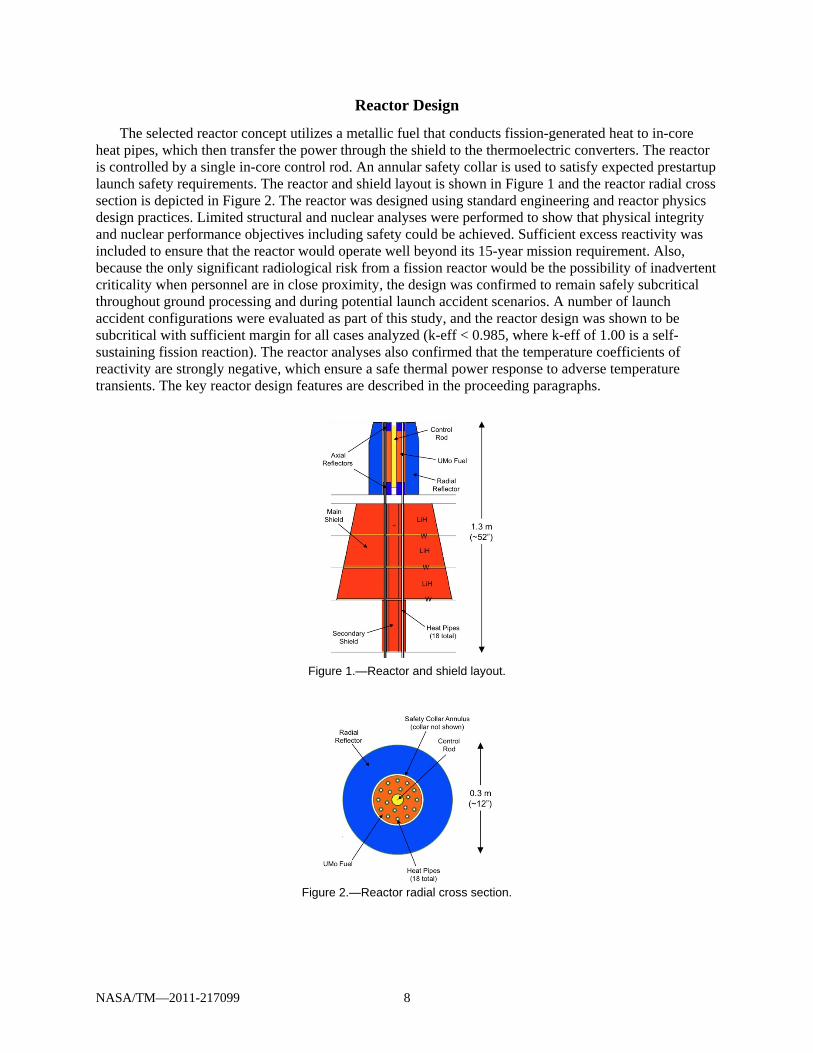
The selected reactor concept utilizes a metallic fuel that conducts fission-generated heat to in-core heat pipes, which then transfer the power through the shield to the thermoelectric converters. The reactor is controlled by a single in-core control rod. An annular safety collar is used to satisfy expected prestartup launch safety requirements. The reactor and shield layout is shown in Figure 1 and the reactor radial cross section is depicted in Figure 2. The reactor was designed using standard engineering and reactor physics design practices. Limited structural and nuclear analyses were performed to show that physical integrity and nuclear performance objectives including safety could be achieved. Sufficient excess reactivity was included to ensure that the reactor would operate well beyond its 15-year mission requirement. Also, because the only significant radiological risk from a fission reactor would be the possibility of inadvertent criticality when personnel are in close proximity, the design was confirmed to remain safely subcritical throughout ground processing and during potential launch accident scenarios. A number of launch accident configurations were evaluated as part of this study, and the reactor design was shown to be subcritical with sufficient margin for all cases analyzed (k-eff < 0.985, where k-eff of 1.00 is a self-sustaining fission reaction). The reactor analyses also confirmed that the temperature coefficients of reactivity are strongly negative, which ensure a safe thermal power response to adverse temperature transients. The key reactor design features are described in the proceeding paragraphs.
Figure 1.—Reactor and shield layout.
Figure 2.—Reactor radial cross section.

NASA/TM—2011-217099 9
Fuel: The fuel selected for the FPS reactor concept is 93 percent enriched U10Mo (uranium with 10 wt% molybdenum). This fuel was selected for its high uranium density, high thermal conductivity, and excellent neutronic characteristics for this application (very low neutron capture at fast energies, modest capture at moderated energies, and inherent gamma shielding). One concern with U10Mo is material swelling at relatively low fuel burnup (~1 percent); however the burnup in this application is so low (~0.1 percent) that swelling is not a significant technical risk. The anticipated form of the U10Mo fuel is cylindrical plates, with the thickness defined by manufacturing and assembly considerations. These plates would contain holes for a central control rod and in-core heat pipes and would be stacked to form a monolithic block. The fueled region is 12.9 cm in diameter and 30 cm tall. For this study, a maximum fuel temperature of 1200 K was imposed, which significantly influences the core and heat pipe geometry.
Core internal structure: One of the key features of the selected concept is that the fuel can provide its own structural support. The fuel assembly would be contained in a can or a liner to preclude material interactions and prevent fission gas release (which may be negligible due to the low burnup), but this envelope is not needed to maintain physical fuel integrity. The low fuel burnup minimizes possible mechanical changes in the fuel that would necessitate structural containment. The advantages of this approach are that it minimizes the amount of neutron-absorbing structural material in the core (keeping the core compact), and it reduces the heat conduction losses through the fuel structure. Molybdenum is a good candidate material for the liner. If some minimal structural material is required, a nickel-based superalloy (e.g., Hastelloy-X) could be used.
Heat pipes: The FPS reactor is cooled by liquid metal heat pipes. The configuration uses 18 heat pipes: 6 in an inner ring and 12 in an outer ring. A ring geometry provides symmetry and simplifies heat pipe routing through the shield and radiator integration. The heat pipe arrangement minimizes the heat transfer distance within the fuel; which keeps the fuel temperature below 1200 K, and the temperature gradients and thermal stresses relatively low. The heat pipe vapor temperature is 1100 K, which led to the selection of a sodium working fluid and superalloy wick and shell. Each heat pipe is 1.11 cm (7/16 in.) in diameter and approximately 4 m long. The heat pipe design includes a factor of two throughput margin, given the nominal heat pipe power of about 750 W, and the peak axial and radial heat fluxes are also well within the established limits. Similar heat pipes have also proven to be reliable at neutron fluences greater than one order of magnitude higher than produced within the FPS core. There are several possible options for thermal integration of the heat pipes with the fuel, including brazing, hot isostatic pressing, or a liquid-metal or gas bonding. As the design evolves, each option would have to be evaluated for technical risk, cost, and reliability.
Neutron reflectors: The neutron reflector material is very important to the FPS concept design. A reflector with a high-reactivity worth is needed not only to keep system size small, but also to make launch safety accidents relatively easy to accommodate. The reflector material specified for most space reactors is Be or BeO: no other candidate material has sufficient reactivity worth to meet the currently assumed launch accident criticality requirements. For the FPS, a compact geometry is highly desirable; thus BeO was chosen because it is a denser and higher worth material per unit thickness than Be. The FPS concept assumes the BeO in brick form within a stainless steel (or superalloy) container. The neutron fluence is expected to be low enough that BeO swelling and cracking should not be a significant technical issue. If later, more detailed design studies indicate that material degradation is an issue, then BeO powder may be substituted; however, the lower density of the powder would necessitate a thicker reflector. The radial reflector surrounding the core is 7.7 cm thick. The upper axial reflector is 5 cm thick and the lower axial reflector is 7 cm thick. The lower reflector optimizes to the thicker geometry because it also provides shielding benefits.
Control rod: Nominal reactor control is performed with a central boron carbide (B4C) control rod that is clad with Hastelloy-X. The rod would be moved by a drive mechanism on the backside of the shield, with a driveshaft penetrating straight through the shield. The control rod contains the required reactivity worth to ensure the reactor can be started from a cold subcritical condition and progress to full-temperature critical operation. One of the significant advantages of the FPS concept is that further reactor control is not required after startup. In eliminating post-startup control rod adjustments, the reactor

NASA/TM—2011-217099 10
temperature will slowly degrade over time, by approximately 3 K per year or 45 K over the entire 15-year mission. The hot end temperature drop would cause a small decrease in reactor thermal power, although the drop in effective heat sink temperature in the outer solar system may counteract this effect, allowing full power throughout the mission. A possible alternative approach would be to design the system for control rod adjustments throughout the mission lifetime, to counteract this small temperature drop and possibly respond to other unanticipated issues.
Safety collar: The simplest design approach to meet the assumed launch accident safety requirements is to place an annular B4C collar between the reactor and the radial reflector. This collar would be removed from the core once the probability of Earth return became negligible. The collar mechanism design would ensure that the safety collar remains in place during launch, but extracted prior to reactor startup.
Radiation shield: The FPS shield utilizes LiH (in stainless steel) as the neutron shield material and W as the gamma shield material. The LiH is enriched in (Ref. 6) Li to reduce the gamma source from neutron capture in the stainless steel and tungsten, and because (Ref. 6) Li is naturally lower mass than (Ref. 7) Li. Tungsten and other high-atomic-mass materials provide excellent gamma attenuation because they reduce the thickness and therefore, the geometric expansion of the shield diameter into the shield cone. The shield utilizes three layers of LiH and W, with each layer of LiH being placed in an individual stainless steel envelope. The shield contains full penetrations for the heat pipes and the control rod shaft. A gap is provided around each heat pipe in which multifoil insulation would be placed to prevent shield heating and parasitic power loss. Shielding calculations showed that the streaming dose through these penetrations accounted for approximately 50 percent of the payload dose. Consequently, a secondary plug shield (see Fig. 1) was added behind the main shield to reduce this streaming dose, with a relatively small mass addition.
Balance-of-Plant Design
To accommodate the targeted electrical power output of 1 kWe and the planned reactor heat pipe operating temperature of 1100 K, the selected concept uses a distributed thermoelectric converter approach integrated with a passive heat rejection radiator structure. The concept is very similar to approaches developed for prior RTGs in that it uses radiative thermal coupling of thermoelectric devices along the length of each of the 18 heat pipes and rejects the heat directly through a finned radiator surface. The key power system performance characteristics are summarized in Table 2.
TABLE 2.—SMALL FPS PERFORMANCE SUMMARY Heat from fission reactor 13,000 W Heat pipe temperature 1100 K Number of heat pipes 18 Heat per pipe 722 W Heat loss 10% Temperature drop from heat pipe to TE couple 50 K TE hot end temperature 1050 K TE cold end temperature 525 K Converter efficiency 9.83% Electrical wiring losses 10% Temperature drop from TE couple to radiator 50 K Effective radiator temperature 475 K Radiator size required 5.035 m2 Radiator panel width (1 panel per heat pipe) 11.7 cm Radiator length required 240 cm System net electrical power output 1035 W Overall system efficiency 7.96%

NASA/TM—2011-217099 11
Figure 3.—Thermoelectric converter concept.
The power conversion assembly consists of 18 panels, each about 12 by 250 cm for a total radiator surface area of 5 m2. Each panel is composed of 21 thermoelectric converters with attached radiator fin as shown in Figure 3. Each converter is coupled to the reactor heat pipe by means of a highly efficient but mechanically compliant heat pipe saddle and radiation coupler that would accommodate thermal expansion of the heat pipe. This type of radiation coupler approach has been successfully used in other space systems, including the International Space Station. The materials selected for the thermoelectric couples include n-type conductivity La3–xTe4/double-filled CoSb3 skutterudite with p-type conductivity Yb14MnSb11 Zintl/filled CeFe3.5Co0.5Sb12 skutterudite (Ref. 5). These materials are stacked in a segmented device configuration similar to that used in proven heritage RTGs (such as Si0.8Ge0.2/Si0.63Ge0.37 materials). The rare earth compounds are currently baselined for operation in next-generation RTGs at temperatures up to 1275 K, well in excess of the requirement for the small FPS application. All of these materials are produced through metallurgy techniques in large batches, and skutterudites are currently targeted for large-scale waste heat-recovery power systems. Efficiencies of approximately 9 to 13 percent have been demonstrated in devices based on these materials.
Taking into account the thermal resistances on both the hot and cold ends of the thermoelectric device, the couples would operate with a 525 K temperature differential (1050 minus 525 K) with a projected efficiency close to 10 percent. The predicted overall system efficiency would be about 8 percent, with a net power output of 1035 W. The thermoelectric devices would be connected in series/parallel strings to match the spacecraft bus voltage of 28 Vdc.
System Configuration and Mass
The basic power system layout geometry and spacecraft interfaces are shown in Figure 4. The reactor is mounted to a truncated-cone radiation shield designed to meet the radiation dose limits assumed in this study (1.0×10¹¹ n/cm2 and 25 krad) at a dose plane 10 m from the reactor/shield interface as shown. The shield provides a conical shadow of radiation protection with a half angle dictated by the separation distance and the diameter of the desired area to be protected at the dose plane, assumed for this study to be 4.5 m. The power conversion and radiators are located behind the shield within the cone angle. A support structure would provide mounting for the power conversion and radiator panels as well as provide the load path from the reactor to the spacecraft. The FPS would interface with the spacecraft through an adapter flange at the base of this support structure. The extension boom that connects the power system to the spacecraft is not included in the FPS mass estimate.
The FPS design configuration is shown in Figure 5. The power system that resulted from this design study has a total length of about 4 m, including the 2.5-m-long radiator panels. The reactor heat pipes extend from the core straight through the shield (shown as partially transparent) and then flare outward to where the radiator panels begin. The secondary plug shield discussed earlier is not shown, but would be inserted behind the main shield to attenuate heat pipe radiation streaming down the straight section of heat pipes. The aluminum radiator panels are rectangular, but are angled to form a conical structure to improve structural rigidity and radiator view factor. A tubular aluminum truss structure supports the radiator panels and extends to the backside of the radiation shield. The truss structure and radiators are fixed and do not require any in-space deployment. The 1.7-m-diameter end skirt would include an adaptor flange to permit spacecraft attachment.

NASA/TM—2011-217099 12
Figure 4.—Concept layout and spacecraft interfaces.
Figure 5.—Small FPS design configuration.
TABLE 3.—SMALL FPS MASS ESTIMATE
Current Best Estimate (CBE),
kg
CBE + Margina, kg
Core assembly 133 159 Heat pipe assembly 19 25 Shield assembly 271 353 Thermoelectric assembly 89 115 Truss assembly 60 78 Inst. and control assembly 32 42 Total small FPS 604
(1.7 W/kg) 772
(1.3 W/kg) aMargin is assumed as 30% for all components except reactor fuel (5%).
The system mass summary is presented in Table 3. The total current best estimate (CBE) mass is 604 kg, or about 1.7 W/kg. The shield assembly has the greatest individual mass at 271 kg, approximately 45 percent of the total. This could be reduced if the radiation limits are relaxed or the separation distance is increased. A 30 percent mass margin was applied to all components with the exception of the reactor fuel. The fuel mass was calculated specifically to meet the required criticality and safety conditions, and a mass margin of 5 percent (which translates to a large reactivity margin) was deemed appropriate for the 56 kg of UMo fuel. The total FPS mass with margin is 772 kg, or about 1.3 W/kg.

NASA/TM—2011-217099 13
Since the shield represents a significant fraction of the total system mass, the team performed a mass sensitivity analysis relative to reactor separation distance. As expected, the analysis showed that greater separation distances result in lower shield mass. In theory, an optimum separation distance results when shield and boom mass are properly balanced. In practice, a larger boom length introduces numerous integration issues including greater difficulty in packaging the spacecraft within the launch vehicle shroud, the possible need for post-launch deployments, and the potential for unstable science-orbit dynamics. Based on the sensitivity analysis performed and the possible spacecraft integration issues that arise with longer booms, it appears that the 10 m separation represents a reasonable design choice.
Spacecraft Integration
The FPS design approach results in a conical configuration similar to all space reactors flown thus far. This packaging lends itself to a relatively straightforward spacecraft integration; the base of the FPS radiator array structure is simply attached to the upper portion of the spacecraft structure. Separation distance of the dose plane from the reactor is most easily achieved through a simple extension of the spacecraft body. This extended structure would provide ample room for propulsion tanks and other equipment that are less susceptible to radiation damage and thus can be closer to the reactor. An example spacecraft configuration, based on the Europa Orbiter mission (Ref. 6), is shown in Figure 6.
The configuration is representative of a typical orbiter design, incorporating a large bipropellant propulsion system for deep space maneuvers and orbit injection. Radiation-sensitive avionics are centrally located in the avionics bus, which begins at the defined dose plane distance of 10 m from the back of the reactor. Science instruments are grouped around the aft end of the spacecraft, which would be nadir-pointed when operating in science orbit. This design lends itself to gravity gradient stabilization and this is easily accommodated by the configuration. The high-gain antenna (HGA) is located on a fixed mount, sufficiently separated from the spacecraft body to allow full articulation while remaining within the reactor shield cone angle. A feature of this design concept is that the higher power available from the FPS can increase telecommunications radiofrequency (RF) power output, facilitating high data return from a relatively small HGA. This feature has a number of benefits, including eliminating the need for antenna booms and deployment, and greatly reducing the tight spacecraft pointing and stability requirements imposed by larger HGAs typically used for such missions.
Figure 6.—Notional FPS-based Europa Orbiter configuration.

NASA/TM—2011-217099 14
Concept-of-Operations
The reactor is launched at ambient temperature and at zero power. The reactor core is not a radiological hazard during launch processing and can be approached by personnel without concern of radiation effects. The reactor is maintained subcritical with essentially no fission activity because it has a neutron-absorbing control rod inserted in the core, and a neutron-absorbing sleeve between the reactor fuel and the reflector. The sleeve must be removed and the rod must be withdrawn to initiate reactor operation. Once the spacecraft is on the appropriate trajectory, the sleeve is removed from its position between the fuel and the reflector using a fault-tolerant ejector mechanism. To start the fission process, the control rod is then gradually withdrawn from the core using a redundant motor drive. A sustained fission reaction would initiate spontaneously once a critical configuration is achieved.
The position of the control rod is adjusted within the core to control the reactor thermal power level. The reactor can sustain a critical reaction at very low power levels. The control rod is adjusted slowly until a statistically significant response is recorded on system neutron detectors. To increase the thermal power level, the control rod is further withdrawn while neutron flux is monitored, until enough power is generated to produce the required thermal response.
Due to the nature of the reactor design, the thermal power output is self regulating once the fuel temperature begins to rise. This negative temperature feedback effect causes the reactor power level to automatically decrease if the reactor temperature increases and to increase if the reactor temperature decreases (in the absence of a control rod adjustment). Once the reactor fuel temperature begins to increase, the temperature feedback mechanisms begin to function and the reactor is then brought to full power and temperature. An increase to full reactor power is expected to occur over a period of approximately 8 hr, but it could be done faster if required.
Heat removal from the core to the power conversion system is the only significant source of heat loss; thus, the reactor power would inherently and correctly respond to changes in the system power demand (intended or otherwise). Therefore, once the reactor is started additional reactivity control is not required for short-term power changes. The reactor power density is low enough that the fuel can be cooled with a combination of passive conduction and heat pipe operation. Therefore, no active control systems related to core cooling are required. Another beneficial feature of low-power operation is that very little fissionable material is consumed. This fact, coupled with the negative temperature coefficient of reactivity allows the reactor to operate at essentially full power and temperature over extended periods without a reactivity adjustment. Current estimates suggest that the electrical power output of the power system would decrease by only 5 percent during a 15-year mission without reactivity adjustment after full power has been achieved.
Reactor startup would be initiated using battery power within a few hours after launch. Once the heat pipes begin operation, the thermoelectric converters would begin producing electrical power to meet spacecraft power needs. The reactor would operate under steady-state full-power conditions throughout the mission and any electrical power not needed by the spacecraft would be diverted to a parasitic radiator and rejected to space. While the study requirement called for continuous power output from the FPS, reactor power adjustments could be accommodated if desired. A possible benefit of reducing thermal power during the mission is the corresponding reduction in reactor-induced radiation at the spacecraft electronics bus.
Extensibility
The design of the small FPS concept is optimized to provide 1 kWe for approximately 15 years. The system is extensible to lower power levels; however, there would be a relatively small mass difference between a 0.5-kWe system and a 1-kWe system because the reactor is already near the minimum size needed to sustain a fission reaction. Extensibility to higher power levels can be divided into two categories—use of the same reactor (e.g., identical core and reflector) and use of the same reactor technology and approach but with some modifications.
NASA/TM—2011-217099 15
In the first category, the same reactor could be used with longer heat pipes and additional distributed thermoelectrics to produce power up to about 1.5 kWe. The use of a more advanced heat pipe wick would allow an additional power increase up to about 2 kWe. A 2-kWe system could also be developed by using thermoelectrics in a compact heat exchanger with secondary heat pipes. The power limit using the same reactor but different power conversion appears to be about 5 kWe; the principal change would be the use of high-efficiency Stirling power conversion instead of thermoelectric conversion (Ref. 7).
For power levels above 5 kWe, several small reactor design changes would be needed. In this second category of extensibility, increasing power to 10 kWe would require a slight change in core volume and the number (or size) of heat pipes. Increasing power beyond 10 kWe would require at least two changes: additional and larger diameter heat pipes, and possibly lower density UMo fuel to accommodate increased uranium burnup. These two changes would result in an increase in reactor size and system mass. Other options for increasing power beyond 10 kWe could include changing to a higher temperature fuel block (e.g., W/UN or Mo/UN cermet) or changing to pin-type fuel.
At power levels above 10 or 20 kWe, the use of superalloy heat pipes to provide primary core cooling may become limiting. For these power levels, a different reactor cooling methodology could be utilized. Pumped liquid metals, refractory metal heat pipes, or direct gas cooling with Brayton power conversion are all possible options. More advanced, higher temperature fuels, heat transport systems, and power conversion technologies would allow fission systems to scale to considerably higher power levels. Although these high-power systems would use different technologies, they would still greatly benefit from the knowledge and experience gained from designing, developing, testing, and flying the 1-kWe FPS.
System Development
Development and verification of the system design and the flight hardware would follow the “test as you fly, fly as you test” maxim to the extent practical. Specifically, the components would be subjected to mechanical, thermal, vacuum, vibration, launch load, material compatibility, radiation, nuclear, functional, electrical, instrumentation, and controls testing. In order to achieve the required test results and provide the most cost-effective approach for system verification, the system testing would be split into two categories: “zero-power” ground nuclear tests and “electrically heated” system tests. Ground-based nuclear testing would confirm the nuclear design. Tests that are of particular interest include 1) verify the amount of subcriticality margin at launch for nominal and accident conditions (e.g., surrounded by water), 2) verify the negative thermal feedback coefficient for the nuclear power as the reactor temperature rises, and 3) verify the control rod position for initial criticality and the rod margin for accommodating heat-up. The first is needed for the launch safety analysis. The second and third are needed for operation and design verification. None of these tests require full-power reactor operation (i.e., 13,000 W-thermal); they can be done with zero-power critical tests using external electrical heaters to achieve the desired temperatures and temperature gradients. In a zero-power critical test, the reactor is in a critical state and is producing a self-sustaining nuclear reaction, but the amount of nuclear power is kept at a very low level (nominally 1 to 10 W-thermal) so that the buildup of radioactive fission products is negligible. This greatly reduces the safety concerns and the cost of the experiment and permits repeated access to the hardware during testing.
The first zero-power critical test can be performed early in the program with a mockup to verify the nuclear material cross sections, the neutron spectrum, and the leakage fraction of the FPS reactor concept. The second set of criticality experiments would be done with a higher fidelity reactor prototype that includes the shield and heat pipes. Electrical heaters wrapped around the core, and heaters and cooling systems on the heat pipes themselves, would allow test engineers to alternately drive heat into the core and remove heat from the core in a manner that could exercise the reactor over a full range of temperatures and temperature gradients that might be encountered with nuclear heating. The nuclear feedback and the nuclear controls could be fully evaluated under these conditions. A zero-power critical acceptance test would also be performed on the flight reactor to verify the control rod position required to achieve criticality.
NASA/TM—2011-217099 16
In the electrically heated tests, the full system would be evaluated with the nuclear heat of the core represented by electrical resistance heaters. Electrically heated testing would include startup, full power operation, and a wide range of operational transients. This approach has been developed over the past decade as a complement to nuclear testing for space FPSs. The simulated core, possibly made using depleted UMo, would have embedded electrical heaters to generate the heat. The design would mimic the heat transfer conditions anticipated at the heat pipes, with similar thermal inertia and materials interactions as expected in the actual nuclear core. The main differences relative to the real core are the radiation environment and the nuclear feedback behavior. However, the heaters can be programmed to simulate the reactor behavior based on analytical models for reactivity feedback. Testing would be used to demonstrate adequate performance margin over an operational range that includes all significant reactivity feedback coefficients, the potential range of values for those reactivity feedback coefficients, and all potential effective delayed neutron fractions. Lifetime testing would also be performed on components to confirm long-term performance and degradation characteristics, using accelerated test methods as practical.
The electrically heated system testing would allow thorough evaluation of the heat transport, power conversion, and heat rejection subsystems in a thermal-vacuum environment while demonstrating control algorithms for both transient and steady-state operations. For the engineering unit, it would lead to design verification that would help ensure the success of the flight system. For the flight unit, it would ensure proper functionality prior to launch. Nuclear feedback effects on the flight unit would be shown to be within acceptable margins by coupling measured reactivity feedback coefficients with full-power electrically heated tests.
This two-pronged approach of zero-power nuclear testing and electrically heated system testing provides a robust verification strategy for the FPS. The testing would provide all the required data to confirm the flight design prior to launch. The key elements would be fully characterized under expected nuclear, thermal, mechanical, and electrical conditions. The combination of this test approach, the low thermal power and energy density of the reactor, the extensive suite of available analytical tools, and the broad nuclear experience base provides confidence that the flight system would meet the intended mission requirements.
Test Facilities
The FPS development effort would employ a number of existing DOE and NASA facilities and test capabilities to support the nuclear design and verification. Existing NASA facilities would permit the non-nuclear mechanical, thermal, vacuum, vibration, launch loads, material compatibility, electrical, instrumentation, and controls testing of individual components or the entire system.
DOE facilities would also be utilized to support the design, development, and fabrication of the nuclear fuels, conduct nuclear irradiations testing, and perform the zero-power critical testing. DOE laboratories and fuel manufacturing capabilities at INL and ORNL would be utilized to develop the fuel manufacturing process and FPS reactor core assembly. Because the flight unit would be fueled with highly enriched uranium (HEU), specialized and dedicated security facilities would be needed. A number of nuclear irradiation facilities are available to perform irradiation experiments on various components, instruments, and materials using neutron or gamma irradiation capabilities. The SNL Gamma Irradiation and the fuel fabrication equipment at the INL are examples of such existing capabilities within the DOE complex. In addition, DOE has recently established capabilities at the Nevada Test Site to perform zero-power critical testing of nuclear reactor cores. Because of the size and type of materials selected for the FPS design, and because other DOE projects have established relevant fuel fabrication, testing, and experimental facilities, it is anticipated that no new facility-related infrastructure would be required for this system. Some facility and process fabrication equipment would need to be installed or modified within the existing facilities to support the FPS fabrication and testing requirements. The project would also explore available university or industrial test capabilities to reduce costs or improve schedule considerations.

NASA/TM—2011-217099 17
Figure 7.—Small FPS development program.
Development Program
The FPS development program is summarized in Figure 7. The 10-year program is organized into three phases: Development (3 years), Engineering (3 years), and Flight Qualification (4 years). A basic set of program-related milestones is shown on the “Program” line. Within each phase, a listing of the key system engineering and testing activities is presented along with the expected National Environmental Policy Act (NEPA) and Launch Approval (LA) products.
Prior to beginning the Development phase, a Concept Development (CD) activity would be conducted to generate a FPS conceptual design and address some of the possible technology risks. The major areas identified for technology risk reduction during this period are 1) fabricate a 4-m sodium heat pipe and demonstrate power throughput at FPS operating temperatures and irradiation levels, 2) fabricate a Zintl/LaTe/SKD thermoelectric module with integral radiator fin and demonstrate power output and efficiency at FPS operating temperatures, and 3) fabricate UMo fuel coupons and characterize mechanical properties and evaluate core fabrication methods. These activities would be conducted in parallel and can be completed within 6 to 8 months with a minimal technology investment. Starting this effort in 2011 would enhance the ability to meet a 2020 flight readiness opportunity.
The FPS Development phase would focus on concept validation. Design requirements would be fully defined and analytical models would be developed. Testing would be performed on components and subassemblies to evaluate performance. An electrically heated power generation test would be completed in thermal-vacuum using a single heat pipe and thermoelectric panel assembly. Material properties and design standards would be formulated and manufacturing processes would be established. The Development phase would culminate with a zero-power critical test of a reactor mockup.
The Engineering phase would verify FPS form, fit, and function. Detailed design drawings would be completed and analytical models would be fully validated with test data. Thermal-vacuum performance testing would be conducted on a full-size, 18-panel engineering model using an electrically heated reactor simulator and spacecraft mockup. Comprehensive vibration and radiation testing of the panel would also be performed. The reactor instrumentation and control elements would be tested to verify performance in an operational environment and the flight software would be validated. A full-size reactor prototype would be fabricated and characterized in a series of zero-power critical tests.
The Flight Qualification phase would deliver the flight system to the launch site. It would include an electrically heated qualification test unit and the actual flight system. The flight system would be fueled and assembled at a DOE facility and delivered to the launch site ready for installation on the spacecraft. Prior to spacecraft integration, a final zero-power critical acceptance test would be performed on the flight reactor. A 1-year spacecraft and launch vehicle integration period was assumed as part of the 10-year development program.

NASA/TM—2011-217099 18
Conclusions
The team successfully developed a viable, low-risk Fission Power System (FPS) concept that can be delivered for launch by 2020 and meet the 1-kWe power output and 15-year lifetime requirements defined for the study. The power system concept consists of a UMo-fueled, heat-pipe-cooled reactor with distributed thermoelectric converters integrated with an aluminum radiator. The system mass is 772 kg (including margin); and the development program can be completed in 10 years. The basic concept can be readily scaled to several kilowatts with thermoelectric conversion or up to 10 kWe using Stirling power conversion with minimal changes to the reactor design. This power system would provide an enabling capability for potential future space science missions that may otherwise be power limited. The technology is highly adaptable to provide significantly greater power using alternative, but similarly mature design approaches.
Although the team completed this study in only 6 weeks, the conclusions are based on a solid foundation of more than 50 years of nuclear engineering and technology development by the Department of Energy (DOE), the National Aeronautics and Space Administration (NASA), the Navy, the Air Force, and private industry. Hundreds of commercial, military, and university reactors are operating safely in the United States today, and hundreds more worldwide, as a result of the Nation’s investment in nuclear technology. The materials, components, and test facilities needed to develop the selected FPS are readily available within the existing U.S. nuclear infrastructure.
Space reactors are not new or particularly complicated. The United States successfully built and launched a space reactor in 1965, and the Russians launched over 30 systems in the years between 1976 and 1988. This type of development has been done before and does not present a major challenge beyond what is routinely done in other space flight systems. For missions requiring 1 kWe or more, fission systems offer the potential for a reliable, low-cost power source that can be reproduced to meet the demands of outer planetary science spacecraft for the next century.
References
1. Bennett, G.L., “A Look at the Soviet Space Nuclear Power Program,” Proceedings of the 24th Intersociety Energy Conversion Engineering Conference, IECEC–89, Washington, D.C., 6-11 August 1989.
2. “Space Reactor Power Systems for 5 to 40 Kilowatts,” A Report of the Evaluation Panel for Small Space Reactor Systems, Prepared for the Air Force Technology Center and the Department of Energy, March 1988.
3. Palac, D.T., Mason, L.S., Houts, M.G., and Harlow, S., “Fission Surface Power Technology Development Update,” AIAA–2010–8711, AIAA SPACE 2010 Conference and Exposition, Anaheim, California, 30 Aug.–2 Sep. 2010.
4. Robinson, A.B., Chang, G.S., Keiser, D.D., Jr., Wachs, D.M., and Porter, D.L., “Irradiation Performance of U-Mo Alloy Based ‘Monolithic’ Plate-Type Fuel - Design Selection,” INL/EXT–09–16807, Idaho National Laboratory, August 2009.
5. Fleurial, J.P., Johnson, K., Mondt, J., Sakamoto, J., Snyder, J., Chen-Kuo Huang, Blair, R., Stapfer, G., Caillat, T., Frye, P., Determan, W., Heshmatpour, B., Brooks, M., and Tuttle, K., “Development of Segmented Thermoelectric Multicouple Converter Technology,” 2006 IEEE Aerospace Conference, Big Sky, Montana, 4–11 March 2006.
6. Clark, K., Tan-Wang, G., Boldt, J., Greeley, R., Jun, I., Lock, R., Ludwinski, J., Pappalardo, R., Van Houten, T., and Yan, T., “Return to Europa: Overview of the Jupiter Europa Orbiter Mission,” 2009 IEEE Aerospace Conference, Big Sky, Montana, 7–14 March 2009.
7. Mason, L., and Carmichael, C, “A Small Fission Power System With Stirling Power Conversion for NASA Science Missions,” Proceedings of Nuclear and Emerging Technologies for Space, NETS–2011, Paper 3326, Albuquerque, New Mexico, 7-10 February 2011.

REPORT DOCUMENTATION PAGE Form Approved OMB No. 0704-0188
The public reporting burden for this collection of information is estimated to average 1 hour per response, including the time for reviewing instructions, searching existing data sources, gathering and maintaining the data needed, and completing and reviewing the collection of information. Send comments regarding this burden estimate or any other aspect of this collection of information, including suggestions for reducing this burden, to Department of Defense, Washington Headquarters Services, Directorate for Information Operations and Reports (0704-0188), 1215 Jefferson Davis Highway, Suite 1204, Arlington, VA 22202-4302. Respondents should be aware that notwithstanding any other provision of law, no person shall be subject to any penalty for failing to comply with a collection of information if it does not display a currently valid OMB control number. PLEASE DO NOT RETURN YOUR FORM TO THE ABOVE ADDRESS.
1. REPORT DATE (DD-MM-YYYY) 01-12-2011
2. REPORT TYPE Technical Memorandum
3. DATES COVERED (From - To)
4. TITLE AND SUBTITLE A Small Fission Power System for NASA Planetary Science Missions
5a. CONTRACT NUMBER
5b. GRANT NUMBER
5c. PROGRAM ELEMENT NUMBER
6. AUTHOR(S) Mason, Lee; Casani, John; Elliott, John; Fleurial, Jean-Pierre; MacPherson, Duncan; Nesmith, Bill; Houts, Michael; Bechtel, Ryan; Werner, Jim; Kapernick, Rick; Poston, David; Qualls, Arthur, Lou; Lipinski, Ron; Radel, Ross; Bailey, Sterling; Weitzberg, Abraham
5d. PROJECT NUMBER
5e. TASK NUMBER
5f. WORK UNIT NUMBER WBS 463169.04.03.01.02
7. PERFORMING ORGANIZATION NAME(S) AND ADDRESS(ES) National Aeronautics and Space Administration John H. Glenn Research Center at Lewis Field Cleveland, Ohio 44135-3191
8. PERFORMING ORGANIZATION REPORT NUMBER E-17606
9. SPONSORING/MONITORING AGENCY NAME(S) AND ADDRESS(ES) National Aeronautics and Space Administration Washington, DC 20546-0001
10. SPONSORING/MONITOR'S ACRONYM(S) NASA
11. SPONSORING/MONITORING REPORT NUMBER NASA/TM-2011-217099
12. DISTRIBUTION/AVAILABILITY STATEMENT Unclassified-Unlimited Subject Category: 20 Available electronically at http://www.sti.nasa.gov This publication is available from the NASA Center for AeroSpace Information, 443-757-5802
13. SUPPLEMENTARY NOTES
14. ABSTRACT In March 2010, the Decadal Survey Giant Planets Panel (GPP) requested a short-turnaround study to evaluate the feasibility of a small Fission Power System (FPS) for future unspecified National Aeronautics and Space Administration (NASA) science missions. FPS technology was considered a potential option for power levels that might not be achievable with radioisotope power systems. A study plan was generated and a joint NASA and Department of Energy (DOE) study team was formed. The team developed a set of notional requirements that included 1-kW electrical output, 15-year design life, and 2020 launch availability. After completing a short round of concept screening studies, the team selected a single concept for concentrated study and analysis. The selected concept is a solid block uranium-molybdenum reactor core with heat pipe cooling and distributed thermoelectric power converters directly coupled to aluminum radiator fins. This paper presents the preliminary configuration, mass summary, and proposed development program. 15. SUBJECT TERMS Space power; Fission power systems; Space reactors
16. SECURITY CLASSIFICATION OF: 17. LIMITATION OF ABSTRACT UU
18. NUMBER OF PAGES
24
19a. NAME OF RESPONSIBLE PERSON STI Help Desk (email:[email protected])
a. REPORT U
b. ABSTRACT U
c. THIS PAGE U
19b. TELEPHONE NUMBER (include area code) 443-757-5802
Standard Form 298 (Rev. 8-98)Prescribed by ANSI Std. Z39-18