a sketch-based collaborative design system - …oliveira/pubs_files/fan_chi_oliveira_collab... · a...
TRANSCRIPT
A Sketch-Based Collaborative Design System
ZHE FAN1 MA CHI
1 MANUEL M. OLIVEIRA
2
1SUNY at Stony Brook – Department of Computer Science, Stony Brook, NY, 11794-4400, USA
{fzhe, mchi}@cs.sunysb.edu 2UFRGS – Instituto de Informática, Caixa Postal 15064, 91501-970, Porto Alegre, RS, Brasil
Abstract. We present a system for collaborative conceptual design that allows users potentially located in geographically distant areas to cooperate by sketching, exploring and modifying their ideas interactively, with immediate visual feedback. The system supports several modeling primitives and can be easily extended with user-defined objects. In this context, we introduce the notions of animated and sketchy billboards. Applications of this system include early stages of urban and landscape design, rapid prototype of virtual environments, animation, education and recreational use.
1. Introduction
Sketching is often used during the early stages of conceptual design when ideas are still unfinished. At this point, the lack of precision implied by the strokes seems to increase the tolerance of the initial estimate of shape [12]. As such, sketches are a powerful tool for communicating ideas among designers and between designers and their customers. While sketching is traditionally performed using pencil and paper, the ability to interactively explore and refine the original thoughts in a collaborative environment can provide a sense of shared design space, allowing the easy creation of different versions of the project and also serving as a valuable teaching tool. Unfortunately, these benefits cannot be fully exploited with the use of pencil and paper. CAD systems, on the other hand, provide considerable editing support, but usually require accurate descriptions of the models, making them less attractive for brainstorming. Although computers can be used to assist in the sketching process [12, 9, 3], creating 3D models directly from a series of 2D strokes is not a well-defined problem, usually lending to undesirable results. As such, just a few applications have been created that try to mimic the process of sketching 3D objects and only do so under some constrained conditions [9, 12].
In some cases, the design task may include distributed teams and remote clients or consultants. In these situations, it would be desirable to allow project members and clients to remotely engage into collaborative design sessions. In practice, however, distributed design often degenerates into co-located design, requiring participants to physically meet in order to overcome the
expressive limitations of traditional communication media, such as phone, fax, e-mail and videoconferencing [16].
We have designed and implemented a conceptual design system that supports collaborative work among groups of users over a network. No artistic skills are required to effectively use the system, which is accomplished by providing a graphical interface, a number of primitives and tools, and a simple mechanism for extending the set of available primitives. In order to avoid the difficulties of creating 3D models directly from 2D strokes, we constrain the use of free-hand sketches to the creation of 2.5D objects. True 3D objects are built from 3D primitives or imported as polygonal meshes and rendered using non-photorealistic (NPR) techniques. Applications of this system include early stages of urban and landscape design, rapid prototyping of virtual environments, animation, and educational and recreational use.
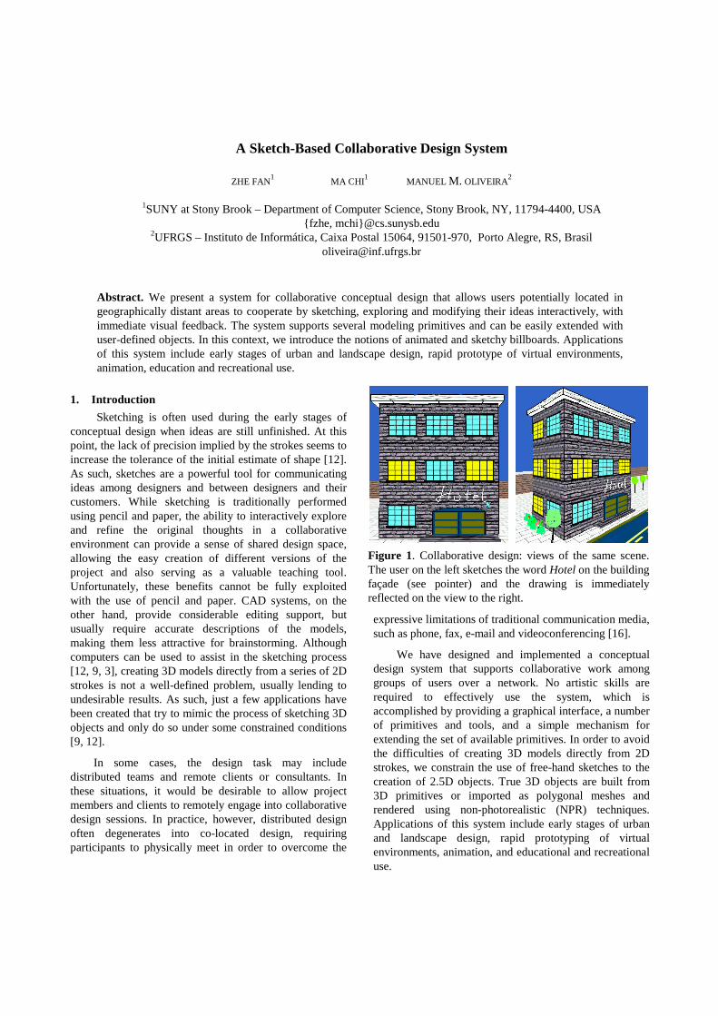
Figure 1. Collaborative design: views of the same scene. The user on the left sketches the word Hotel on the building façade (see pointer) and the drawing is immediately reflected on the view to the right.
We demonstrate the effectiveness of our system by having users with no specific artistic skills create pleasing 3D environments in just a few minutes. Figure 1 illustrates this for the case of an urban design. The two images correspond to the views of two designers, who independently explore the space but whose modeling actions become immediately visible to all participants. The image on the left shows the result of one user handwriting the word Hotel on the building façade (note the pointer). On the right, the other designer observes the same building from a different viewpoint with the letters being projected with correct perspective.
The remaining of the paper is structured as follows: Section 2 discusses some related work. Section 3 presents the architectural details of our system. Section 4 comments some of the results obtained with the implementation of the proposed architecture. Section 5 concludes the paper with a summary and directions for future exploration.
2. Related Work
Computer Supported Cooperative Work (CSCW) corresponds to the use of computers to support and enhance the work activities of groups [2, 4]. The technical aspects involving the design of collaborative systems and their associated infrastructures are particularly challenging, especially because most CSCW applications can potentially support a large number of users. Our system, on the other hand, is intended for conceptual design, a creative task involving a relative small number of concurrent users, which significantly simplifies its design.
Networked virtual environments (net-VEs) are distributed graphical applications that allow multiple users to interact in real time, providing a shared sense of space, presence and time, as well as a way to communicate [7, 11]. The fundamental difference between our system and net-VEs is our emphasis on design. While most net-VE systems are intended for long-term exploration, by a large number of users, we emphasize the collaborative aspects of design. In this case, small groups create environments from scratch during interactive sessions.
SKETCH is an interface for creating and editing 3D sketches of scenes [12]. It is based on the use of simplified (2D) drawing commands, which are interpreted as operations to be applied to objects within a 3D world. In this case, all objects are 3D and rendered in orthographic views. Like SKETCH [12], our system is oriented towards rapid creation of approximate representation of environments. Unlike SKETCH, however, our system is a distributed application, uses perspective views for sketching and environment exploration, supports 2D, 2.5D and 3D objects, and can import and export 3D models
from and to other modelers. NetSketch [16] is an application based on the SKETCH interface [12] that supports distributed conceptual design. In spirit, this is the closest to our work, but scene models are constrained to the relatively simple shapes that can be created and rendered using SKETCH. NetSketch uses a peer-to-peer network topology and cannot always guarantee model consistency among all users. Our system, on the other hand, is based on a client-server model, enforcing a consistent view among all participants. SketchUp [14] is a conventional 3D modeling application that supports sketchy-like renderings of the models. It mimics architect drawings by rendering jittered lines, extended edges and by using non-photorealistic techniques.
CALVIN [6] is a networked collaborative environment for designing indoor architectural spaces. Conceptualy, our system is somewhat similar to it, but CALVIN was designed to run in a CAVE and requires the use of VR equipment. Our system, on the other hand, is based on comodity PCs, uses a much simpler interface (CALVIN also uses verbal and video communication channels) and exploits non-photorealistic rendering.
Alice [8] is a prototyping tool for virtual reality applications that allows the programmer to focus on the content of the application. Alice is a flexible and extensible environment, but it requires its users to have some programming skills. Akeo et al. [1] demonstrated an interface for creating 3D models from idea sketches. Their system was targeted towards industrial design and their goal was to produce as good approximations as possible from the final object. Teddy [5] is an interface for creating 3D plausible models from 2D sketches of silhouettes. The resulting freeform models consist of texture-mapped 3D meshes. Branco, Costa and Ferreira [3] combine 2D sketches with extrusion and other CSG operations to create 3D models of simple geometric objects. Tolba, Dorsey and McMillan [15] showed how a 2D projective drawing system could be used to mimic 3D-like capabilities.
3. System Architecture
The number of concurrent users in a collaborative design session is usually limited to just a few designers and the rate at which the environment changes is relatively low. Also, in this kind of application, changes in the design need to be perceived by the users at interactive rates, but not necessarily in real time (i.e., delays of up to a couple of seconds can be tolerated).
The architecture of our system was based on these observations and consists of a client-server application over the Internet. Clients (user sessions) connect to a
server using BSD sockets and TCP/IP protocol [13]. The use of TCP greatly simplified the system’s implementation due to its reliable communication and ordering semantics. These benefits more than compensate for the small delay imposed by its ordering semantics itself. The server is responsible for maintaining a consistent state of the design and for forwarding the updates to all clients in the session. The small number of clients justifies the use of a single server. In the event of a server failure, clients can keep exploring their cached copies, save changes to local databases and later send the updates to the server.
As a user creates a new object, this information is immediately sent to the server who stores it in a database, records the object’s ownership, and forwards the update to all other clients sharing the session. An equivalent sequence of messages is exchanged when an object is deleted or modified.
From a user’s viewpoint, the most important part of the system is its graphical user interface, which is used for sketching, management and exploration of the resulting 3D environments. The user interface is discussed next.
3.1 User Interface
The system’s interface is logically organized in six modules, called managers, as shown in Figure 2. Each of these modules is explained next.
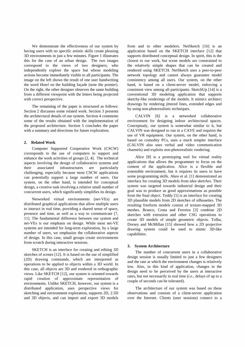
Floor and Viewer Managers: The Floor Manager provides a top view of the whole environment, allowing users to immediate locate, select, group, move, delete, add or re-scale any object in the scene. It consists of a square (scrollable) grid showing 2D representations of the camera (position and orientation) and of all objects in the scene (Figure 3 right). The Viewer Manager provides a perspective view of the environment from the camera’s viewpoint, allowing interactive exploration of the scene (Figure 3 left).
2D Manager: Sketching is performed directly on the perspective view. As the user sketches on the screen, the drawing is buffered as a set of 2D line segments, which are later projected into the 3D environment. First, the bottommost vertex is projected onto the ground plane,
defining a root point (Figure 4) (a similar technique is used in [12] to decide where to position an object in 3D). The coordinates of the new 3D vertices are obtained by projecting the buffered 2D vertices onto the plane α passing through the root point and parallel to the camera’s plane (Figure 4). Finally, the sketch is stored and rendered as a series of line segments in 3D. As the user walks through the scene, the sketch is rotated so that it always faces the viewer. We refer to this kind of objects as sketchy billboards, which were used to create the trees and grass shown in Figures 1, 6, 7 and 8.
Support is also provided for sketching directly on 3D objects. This feature is illustrated in Figures 1 and 3, where the words Hotel and Block were handwritten on the building façade and on one side of the box, respectively. The process is similar to the one just described, but, in this case, the planes onto which the sketches are projected on are found by casting rays through the vertices of the strokes into the scene. The new sketches then become attributes of the closest intersected faces.
3D Manager: The construction of 3D environments can be greatly simplified if some 3D primitives are on hand and if one can take advantage of the arsenal of 3D models available as polygonal meshes. Our system supports geometric primitives and polygonal meshes, which are rendered using NPR techniques. This flexibility allows the system to both import and export 3D models to other modelers.
Examples of geometric primitives include boxes, pyramids, wedges, cylinders, polygons, etc. In order to
Figure 2. The six modules of the graphical user interface.
Image Manager
3D Manager
2D Manager
Floor Manager
Interface
Library Manager
ViewerManager
Figure 3. 3D view of the scene (left). Floor manager (right): The camera is represented as a v-shaped icon.
Figure 4. Mapping 2D sketches into the 3D
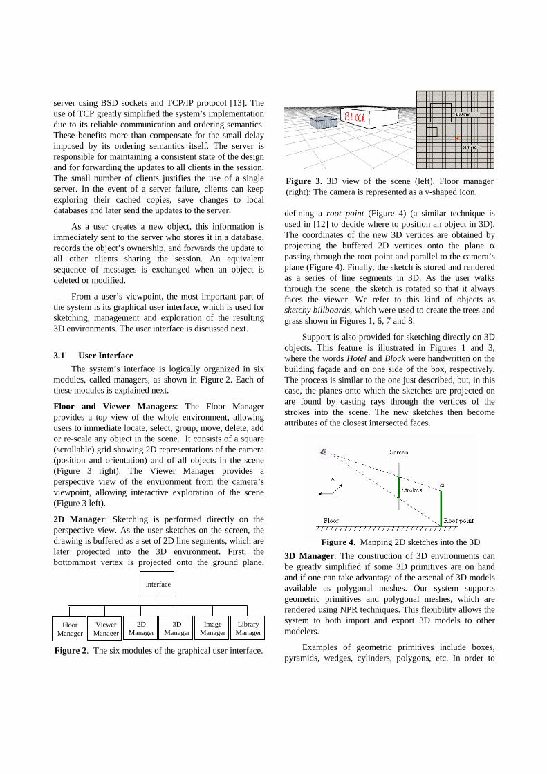
give these primitives a sketch-like appearance, we assign artificial edges to each primitive by subdividing its original edges into a certain number of segments (this number is a function of the length of the edge itself) and applying a random offsets to the internal vertices of the segments. These artificial edges are then stored with the original primitives. The rendering consists of drawing the original primitives without outlines followed by the rendering of the artificial edges. The rendering of the original primitives greatly simplifies texture mapping. This is essentially what is used to render polygonal objects in SKETCH [12]. Figure 5 shows a side-by-side comparison of the renderings of some 3D primitives using conventional OpenGL rendering (left) and the sketchy rendering procedure described (right). The buildings shown in Figures 1, 8 and 9 and the farmhouse shown in Figure 6 were created by texture mapping 3D geometric primitives. Imported polygonal meshes are rendered using silhouette and importance edges [10].
Image Manager: It provides a number of important features, which include animated billboards, user-defined textures, impostors and background images. A billboard is a texture-mapped polygon that always faces the viewer, replacing some amount of 3D geometry. Animated billboards extend the traditional notion of a billboard by allowing its associated texture to change over time and are especially effective for representing amorphous elements, such as clouds, fire and water, traditionally represented using particle systems and procedural modeling. In animated billboards, the individual frames of the associated animation are cyclically mapped onto the corresponding polygon. Despite its simplicity, this technique is quite effective and was used to animate the water fountain shown in Figure 8 (see the accompanying video showing the town exploration).
Although any 2D texture can be imported into our system, it provides some painting features to let users create and edit their own textures. Such a feature was used to create the windows of the buildings in town (Figures 1 and 8) as well as the door and window textures used in the farmhouse (Figure 6). A special color is reserved to represent transparency, allowing textures to have arbitrary
shapes. Far away geometry can be represented as planar impostors [17]. This is illustrated in Figure 8 for the case of the buildings in the back. The system also supports the use of bitmaps as background images for the environments. This provides an easy and efficient way to visually enrich a scene. It also provides a way to represent and switch between, for example, various times of the day and different weather conditions. Examples of backgrounds can be seen in the sky representations used in images Figures 6 and 8.
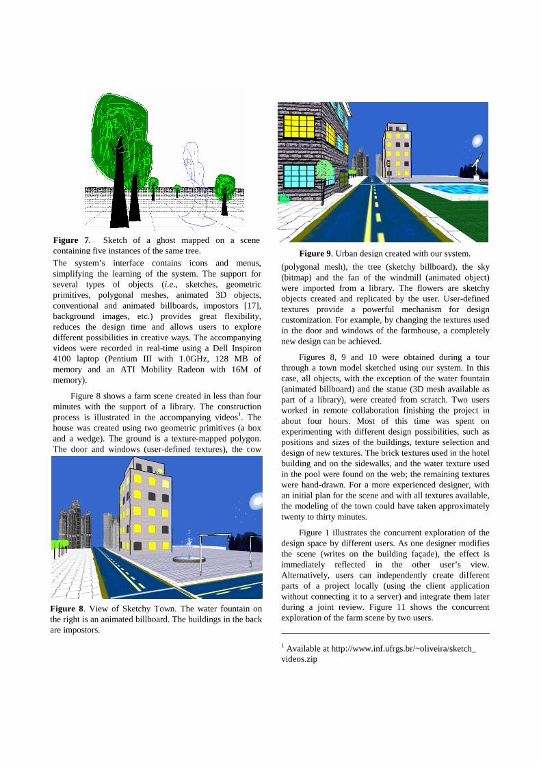
The Image Manager also provides other features such as a simple painting system and tools for image manipulation. These can be used in combination with other tools to enhance the quality of the sketches. Figure 7 shows a scene with five instances of the same tree. To create its leaves, a closed curve was outlined in 2D and filled in green. Likewise, the trunk was outlined and filled in brown. Finally, branches and light green lines were added. The resulting tree model consists of two polygons (leaves and trunk) and additional lines in 3D (branches and light lines). Its rendering is performed in a similar way as other sketch objects, always facing the camera. The tree was saved in a library and used in the farm scene shown in Figure 6. The ghost also shown in Figure 7 was created using the sketching procedure.
Library Manager. The capabilities of the system can be extended in an easy and flexible way by user-defined libraries. A library is an arbitrary set of objects supported by the system and provides a natural way for grouping related entities and for sharing them with other users.
4. Results
We have implemented the described system architecture in C++ and OpenGL and used it to create several virtual environments in a collaborative fashion.
Figure 5. Rendering of 3D primitives. Conventional rendering (left). Sketchy rendering (right).
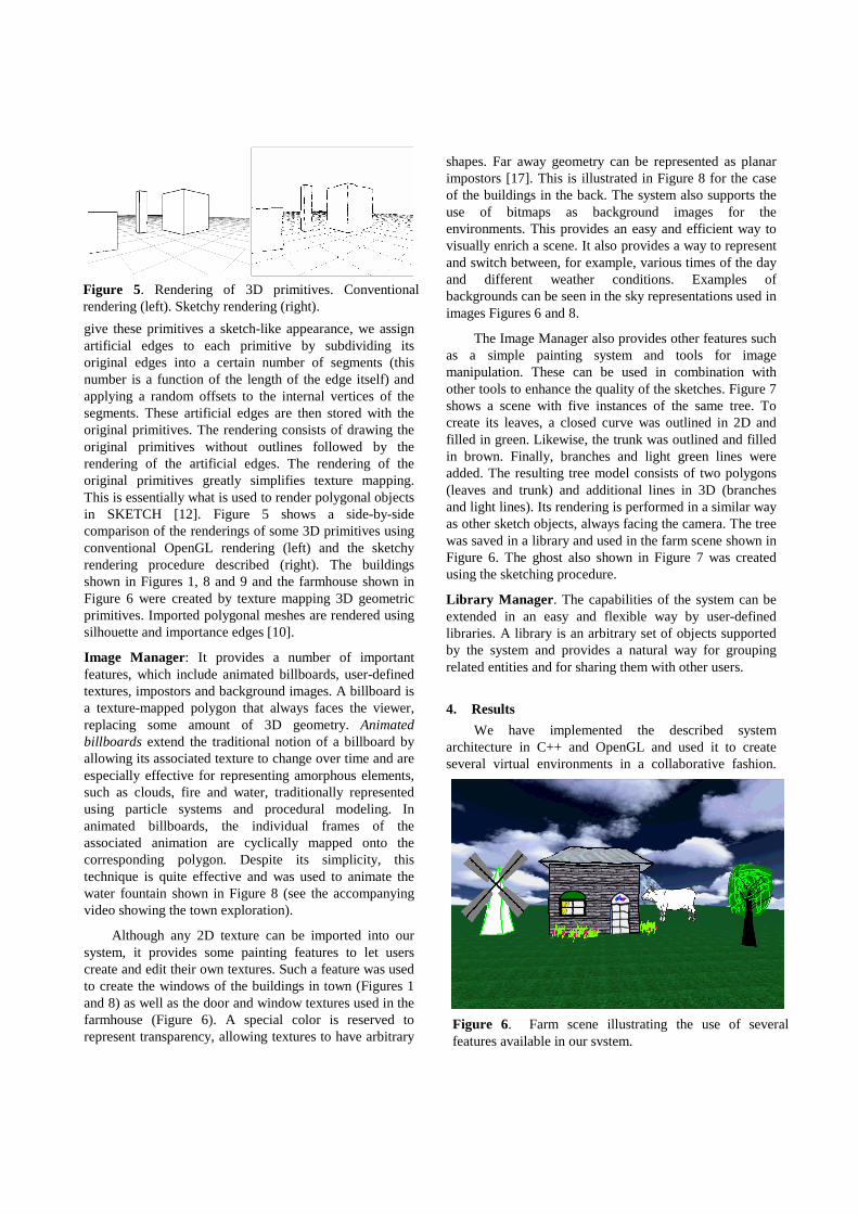
Figure 6. Farm scene illustrating the use of several features available in our system.
The system’s interface contains icons and menus, simplifying the learning of the system. The support for several types of objects (i.e., sketches, geometric primitives, polygonal meshes, animated 3D objects, conventional and animated billboards, impostors [17], background images, etc.) provides great flexibility, reduces the design time and allows users to explore different possibilities in creative ways. The accompanying videos were recorded in real-time using a Dell Inspiron 4100 laptop (Pentium III with 1.0GHz, 128 MB of memory and an ATI Mobility Radeon with 16M of memory).
Figure 8 shows a farm scene created in less than four minutes with the support of a library. The construction process is illustrated in the accompanying videos1. The house was created using two geometric primitives (a box and a wedge). The ground is a texture-mapped polygon. The door and windows (user-defined textures), the cow
(polygonal mesh), the tree (sketchy billboard), the sky (bitmap) and the fan of the windmill (animated object) were imported from a library. The flowers are sketchy objects created and replicated by the user. User-defined textures provide a powerful mechanism for design customization. For example, by changing the textures used in the door and windows of the farmhouse, a completely new design can be achieved.
Figures 8, 9 and 10 were obtained during a tour through a town model sketched using our system. In this case, all objects, with the exception of the water fountain (animated billboard) and the statue (3D mesh available as part of a library), were created from scratch. Two users worked in remote collaboration finishing the project in about four hours. Most of this time was spent on experimenting with different design possibilities, such as positions and sizes of the buildings, texture selection and design of new textures. The brick textures used in the hotel building and on the sidewalks, and the water texture used in the pool were found on the web; the remaining textures were hand-drawn. For a more experienced designer, with an initial plan for the scene and with all textures available, the modeling of the town could have taken approximately twenty to thirty minutes.
Figure 1 illustrates the concurrent exploration of the design space by different users. As one designer modifies the scene (writes on the building façade), the effect is immediately reflected in the other user’s view. Alternatively, users can independently create different parts of a project locally (using the client application without connecting it to a server) and integrate them later during a joint review. Figure 11 shows the concurrent exploration of the farm scene by two users.
1 Available at http://www.inf.ufrgs.br/~oliveira/sketch_ videos.zip
Figure 8. View of Sketchy Town. The water fountain on the right is an animated billboard. The buildings in the back are impostors.
Figure 9. Urban design created with our system.
Figure 7. Sketch of a ghost mapped on a scene containing five instances of the same tree.
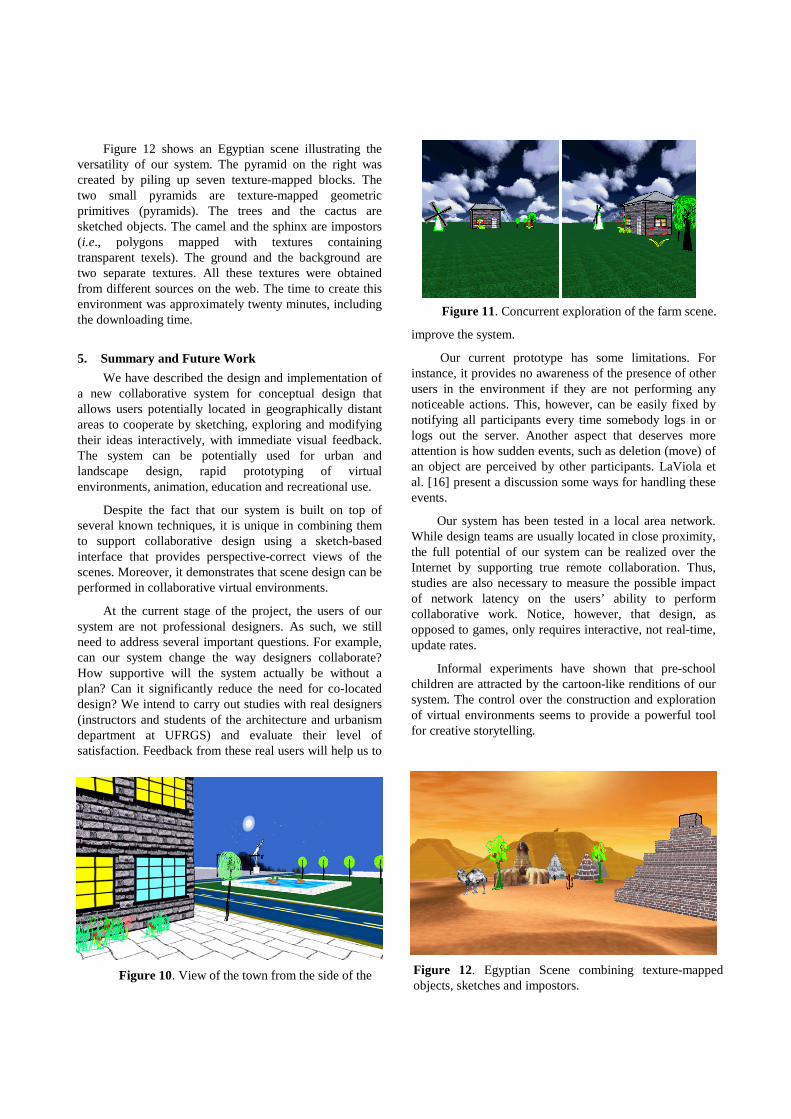
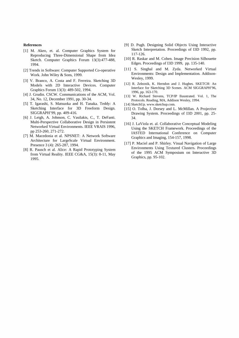
Figure 12 shows an Egyptian scene illustrating the versatility of our system. The pyramid on the right was created by piling up seven texture-mapped blocks. The two small pyramids are texture-mapped geometric primitives (pyramids). The trees and the cactus are sketched objects. The camel and the sphinx are impostors (i.e., polygons mapped with textures containing transparent texels). The ground and the background are two separate textures. All these textures were obtained from different sources on the web. The time to create this environment was approximately twenty minutes, including the downloading time.
5. Summary and Future Work
We have described the design and implementation of a new collaborative system for conceptual design that allows users potentially located in geographically distant areas to cooperate by sketching, exploring and modifying their ideas interactively, with immediate visual feedback. The system can be potentially used for urban and landscape design, rapid prototyping of virtual environments, animation, education and recreational use.
Despite the fact that our system is built on top of several known techniques, it is unique in combining them to support collaborative design using a sketch-based interface that provides perspective-correct views of the scenes. Moreover, it demonstrates that scene design can be performed in collaborative virtual environments.
At the current stage of the project, the users of our system are not professional designers. As such, we still need to address several important questions. For example, can our system change the way designers collaborate? How supportive will the system actually be without a plan? Can it significantly reduce the need for co-located design? We intend to carry out studies with real designers (instructors and students of the architecture and urbanism department at UFRGS) and evaluate their level of satisfaction. Feedback from these real users will help us to
improve the system.
Our current prototype has some limitations. For instance, it provides no awareness of the presence of other users in the environment if they are not performing any noticeable actions. This, however, can be easily fixed by notifying all participants every time somebody logs in or logs out the server. Another aspect that deserves more attention is how sudden events, such as deletion (move) of an object are perceived by other participants. LaViola et al. [16] present a discussion some ways for handling these events.
Our system has been tested in a local area network. While design teams are usually located in close proximity, the full potential of our system can be realized over the Internet by supporting true remote collaboration. Thus, studies are also necessary to measure the possible impact of network latency on the users’ ability to perform collaborative work. Notice, however, that design, as opposed to games, only requires interactive, not real-time, update rates.
Informal experiments have shown that pre-school children are attracted by the cartoon-like renditions of our system. The control over the construction and exploration of virtual environments seems to provide a powerful tool for creative storytelling.
Figure 10. View of the town from the side of the Hotel.
Figure 11. Concurrent exploration of the farm scene.
Figure 12. Egyptian Scene combining texture-mapped objects, sketches and impostors.
References
[1] M. Akeo, et. al. Computer Graphics System for Reproducing Three-Dimensional Shape from Idea Sketch. Computer Graphics Forum 13(3):477-488, 1994.
[2] Trends in Software: Computer Supported Co-operative Work. John Wiley & Sons, 1999.
[3] V. Branco, A. Costa and F. Ferreira. Sketching 3D Models with 2D Interactive Devices. Computer Graphics Forum 13(3): 489-502, 1994.
[4] J. Grudin. CSCW. Communications of the ACM, Vol. 34, No. 12, December 1991, pp. 30-34.
[5] T. Igarashi, S. Matsuoka and H. Tanaka. Teddy: A Sketching Interface for 3D Freeform Design. SIGGRAPH’99, pp. 409-416.
[6] J. Leigh, A. Johnson, C. Vasilakis, C., T. DeFanti. Multi-Perspective Collaborative Design in Persistent Networked Virtual Environments. IEEE VRAIS 1996, pp 253-260, 271-272.
[7] M. Macedonia et al. NPSNET: A Network Software Architecture for LargeScale Virtual Environment. Presence 3 (4): 265-287, 1994.
[8] R. Pausch et al. Alice: A Rapid Prototyping System from Virtual Reality. IEEE CG&A, 15(3): 8-11, May 1995.
[9] D. Pugh. Designing Solid Objects Using Interactive Sketch Interpretation. Proceedings of I3D 1992, pp. 117-126.
[10] R. Raskar and M. Cohen. Image Precision Silhouette Edges. Proceedings of I3D 1999, pp. 135-140.
[11] S. Singhal and M. Zyda. Networked Virtual Environments: Design and Implementation. Addison-Wesley, 1999.
[12] R. Zeleznik, K. Herndon and J. Hughes. SKETCH: An Interface for Sketching 3D Scenes. ACM SIGGRAPH’96, 1996, pp. 163-170.
[13] W. Richard Stevens, TCP/IP Iluustrated. Vol. 1, The Protocols. Reading, MA, Addison Wesley, 1994.
[14] SketchUp. www.sketchup.com. [15] O. Tolba, J. Dorsey and L. McMillan. A Projective
Drawing System. Proceedings of I3D 2001, pp. 25-34.
[16] J. LaViola et. al. Collaborative Conceptual Modeling Using the SKETCH Framework. Proceedings of the IASTED International Conference on Computer Graphics and Imaging, 154-157, 1998.
[17] P. Maciel and P. Shirley. Visual Navigation of Large Environments Using Textured Clusters. Proceedings of the 1995 ACM Symposium on Interactive 3D Graphics, pp. 95-102.