a sip-based voip application in enhanced ethernet … · ethernet passive optical network (epon)...
TRANSCRIPT
Abstract—Since the inception of telephony, the public switch
telephone network (PSTN) has had major impact in everyday
life. The widespread adoption of VoIP has totally revolutionized
the telephony industry. With many free services for the users,
VoIP is favored over the traditional PSTN. A major concern for
VoIP is voice quality, as it is a network-based packet switching
technology. VoIP will come in handy in enterprise networks,
where voice and data service are often separated networks. With
the provisioning of multiple service type in a single network with
a common IP network infrastructure, this will reduce the
operational cost as it is easier to run, maintain and manage such
networks. With all the nifty features of VoIP a major concern
for service providers is bandwidth availability. VoIP requires
high-bandwidth, with minimum delay and if possible, no packet
loss. Ethernet passive optical network (EPON) is regarded as the
best solution in access networks in providing the high bandwidth
requirements for VoIP Services, and other multimedia
application. In this paper, we propose a new architecture that
incorporates a VoIP server in the Optical Line Terminal (OLT).
A fully functioning VoIP telephony system will be implemented
in the OLT that will be able to handle all the telephony services
for users. Our simulation results show that the VoIP Server can
be implemented in the EPON and the constraints of VoIP such
as delay jitter and packet loss is improved, and hence a better
Quality of Service (QoS).
Index Terms—PSTN, SIP, VoIP, EPON, Service Providers,
QoS.
I. INTRODUCTION
The current number of telephone line has exceeded over 1
billion users and about 6.8 billion mobile-cellular
subscriptions in the world [1]. The Public Switch Telephone
Network (PSTN) is still where the majority of voice calls are
carried. The well-engineered PSTN uses circuit switching
technology, which reserves resources along the entire
communication channel for the duration of a given call. This
has brought about the quality that it provided for the past
100years. In recent years, we have seen many developments
and new services coming to market, services that the PSTN
cannot fully handle. Services like voice email, soon,
telephony service providers will move to networks, based on
Manuscript received January 03, 2014; revised January 28, 2014
Lamarana Jallow is (email:[email protected]) with
Department of Computer Science and Engineering, Yuan-Ze University,
Chung-Li, 32003, Taiwan.
I-Shyan Hwang (e-mail:[email protected]) is with
Department of Information Communication, Yuan-Ze University, Chung-Li,
32003, Taiwan.
AliAkbar Nikoukar is (email:[email protected]) with
Department of Computer Science and Engineering, Yuan-Ze University,
Chung-Li, 32003, Taiwan.
Andrew Tanny Liem (email:[email protected]) is with
Department of Computer Science and Engineering, Yuan-Ze University,
Chung-Li, 32003, Taiwan.
open protocols known as voice over Internet protocol (VoIP)
[2]. Operational cost will be reduced, with the provisioning of
multiple service types in a single network with a common IP
network infrastructure. As voice and data are in the same
network, this will be easier to run, maintain and manage [3].
VoIP also known as Internet telephony, is the ability to
transmit voice communication over the packet-switched IP
networks. VoIP has revolutionized telephone communication,
as it is cheaper for the end users. Other additional features
which the users previously had to pay for are offered for free,
features like caller ID, call waiting, call forwarding and call
conferencing. Moreover, extended services also come up with
establishment of VoIP, which includes emailed voicemail and
easy management of phone contacts.
Service providers can offer some added services by
including VoIP telephony for the users, with which they can
manage the network that can comprise of voice, video and
data.
The integration of all traffic types onto a single network
may seem nifty, but a few problems are realized. While cost
reduction, new functionality and increased mobility are
realized. With the introduction of VoIP to the existing
networks, this will result in bad voice quality for VoIP when
compared to PSTN. VoIP requires packets to be delivered
with strict timing; low latency, jitter, packet loss and sufficient
bandwidth.
To set up and tear down calls, Signaling Protocols are
needed to establish the telephone calls over the internet. The
role of signaling protocols can be broken down into four
functions - User Location, Session Establishment, Session
Management and Call Participant Management. H.323,
Session Initiation Protocol (SIP), Media Gateway Control
Protocol (MGCP), SKYPE are some protocols architectures
that can be used as signaling protocols. The debate is adopting
a protocol that has quality as close to as the PSTN and
deployment might differ from market to market. Due to
simplicity, scalability and low overhead, SIP can be
implemented in networks of any size. SIP is more flexible in
the sense that it covers intentionally only subsets of
functionality needed for VoIP Telephony and is characterized
with the ability to be used with different transport and other
protocols [4]. SIP performed better when compared with
H.323 under extreme traffic congestion and different queuing
policies. And a higher percentage of successful call
establishments were achieved with SIP when compared to
H.323 [5].
The Session Initiation Protocol (SIP) is the IETF protocol
for VOIP and other text and multimedia sessions, widely used
for controlling multimedia communication sessions such as
voice and video calls over Internet Protocol (IP). SIP is used
A SIP-based VoIP Application in Enhanced
Ethernet Passive Optical Network Architecture
Lamarana Jallow, I-Shyan Hwang, AliAkbar Nikoukar, Andrew Tanny Liem
Proceedings of the International MultiConference of Engineers and Computer Scientists 2014 Vol II, IMECS 2014, March 12 - 14, 2014, Hong Kong
ISBN: 978-988-19253-3-6 ISSN: 2078-0958 (Print); ISSN: 2078-0966 (Online)
IMECS 2014

for creating, modifying and terminating of sessions and also
how a call is established, how voice data is transferred during
call with one or more participants, and also the termination of
the session. SIP is similar to how HyperText Transfer
Protocol (HTTP) functions, and shares some of its design
principles. It typically adopts a client-server architecture
(request/response). Client generates requests and sends to the
server. After the request is processed, the response is then sent
to the server. Similar to HTTP, SIP is based on text-based
messages. The messages are exchanged between clients and
the servers as either requests or responses. The INVITE
request is the most important type of request and is used to
invite a user to a call. The ACK request which the caller sends
to the callee to simply acknowledge the receipt of the latter’s
response. The BYE request is used to terminate the session
between two users Figure 1 explains the basic component of
SIP calling mechanism.
There are a number of available SIP based Open Source
VoIP soft-switch platforms, providing rich telephony services
[6]. It offers a wide range of features to end users (call
forwards, voicemail, conferencing, call blocking,
click-to-dial, call-lists showing near-real-time accounting
information, etc.), which can be configured by them using the
customer-self-care web interface. A web-based administrative
panel is provided for operators, allowing them to configure
users, peering, billing profiles, etc., and also the possibility of
viewing real-time statistics of the system.
Deploying passive optical networks (PON) from the
service providers to be as close as possible to the customers
will give the required bandwidth for customers various
multimedia service need, at a very cost efficient and flexible
infrastructure from both parties. A PON is a form of fiber
optic access network. Access networks provide end-user
connectivity. They are placed in close proximity to end users
and deployed in large volumes. Access networks exist in
many different forms for various practical reasons. In an
environment where legacy systems already exist, carriers tend
to minimize their capital investment by retrofitting existing
infrastructure with incremental changes. Compared to
traditional copper-based access loops, optical fiber has
virtually unlimited bandwidth (in the range of tera-hertz or
THz of usable bandwidth). Deploying fiber all the way to the
home therefore serves the purpose of future proofing capital
investment.
PON offers many system architectures, the EPON is
regarded as the best solution for access networks due to its
simplicity, high data rate, and low cost compared to the other
PONs [7]. EPON is based on Ethernet standard, which makes
it easy to deploy from the central office to customer premises.
EPON is generally deployed in a tree like topology, using
passive (non-active electronics within the access network)
1:N splitter. The optical line terminal (OLT) is located at the
central office and N number of optical network units (ONUs)
is close to the customer premises. In EPON, multi-point
control protocol (MPCP) is used to control the P2MP fiber
networks. The MPCP is implemented at the medium access to
control layer to perform the bandwidth allocation,
auto-discovery process, and ranging. Two control messages -
Gate message, which carries the granted bandwidth
information from the OLT to ONU in the downward
direction; and REPORT message, which is used by ONU to
report its bandwidth request (local queue length) to the OLT
in upstream direction [7]. Due to the many traffic types the
ONU is capable of supporting up to eight priority queues.
After each ONU sends there report message based on queue
state information, to the OLT. The OLT executes the
Dynamic Bandwidth Allocation (DBA), which calculates and
allocates the transmission timeslot for each ONU based on
their queue state information. The DBA plays a major role in
providing an efficient bandwidth allocation scheme for the
ONUs to share the network resources accordingly, and also to
provide better Quality of Service (QoS) for the end users.
In this paper, we propose an OLT architecture that contains
the VoIP server (VoS) by using the Field-programmable gate
array (FPGA). The rest of the paper is organized as follows.
Section II talks about the related work, the proposed
architecture is introduced in section III. The performance
evaluation is explained in section IV, followed by the
conclusion in Section V.
II. RELATED WORK
If the VoIP is to be adopted in every organization there
should be a mechanism in place to handle as many calls at a
time. Bandwidth and architecture is a major concern for
network operators and carriers. [8] shows a maximum of 12
calls can be achieved in wireless Local Area Networks. As to
lease line traffic, circuit emulation servicer over packets
(CESoP) is a simple and cost effective solution for
“tunneling” TDM circuits through a packet-switched
network. Although CESoP also supports voice application, it
is more costly and complex compared to the cost of
implementing a VoIP based solution [9].
The token bucket (TB) is used as policing unit, which
monitors the traffic entering the network. Being between a
VoIP host and an ingress node, it ensures that the generated
traffic conforms to a certain pre-determined profile. In case
the traffic violates this profile, the TB policer drops incoming
packets in a way to make the outgoing traffic fit the given
profile [10]. In this case it will be observed a significant
amount of packets will be dropped causing impossible voice
communication, when there is a number of simultaneous calls.
With VoIP servers typically located outside our reach,
Skype in particular, which is also proprietary. Having the
VoIP server closer to the users will decrease some of the
packet delays usually caused by the long distance calls.
SIP client([email protected])
SIP client([email protected])
SIP Proxy Server
1. Registered SIP Clients
2. User calls destination number and the SIP Proxy server receives its request
4. Proxy server informs the destination client:
phone rings
5.When call is answered, SIP clients opens RTP session
3. Destination URL looked up by Proxy server, and invite message is sent to
client
RTP Session
Network
Fig. 1. Basic call flow of SIP
Proceedings of the International MultiConference of Engineers and Computer Scientists 2014 Vol II, IMECS 2014, March 12 - 14, 2014, Hong Kong
ISBN: 978-988-19253-3-6 ISSN: 2078-0958 (Print); ISSN: 2078-0966 (Online)
IMECS 2014

With all the pretty features of VoIP, there are so many
problems that arise. VoIP promised so many fancy features
which are offered for free of service to consumers. Bandwidth
has been a major concern ever since the inception of the
internet. Applications like IPTV, video on demand, VoIP,
online gaming and so on are huge consumers of bandwidth.
For the past 100 years, the quality of the call service
provided by the PSTN has always been on point. A
tremendous amount of work has to be done for VoIP to equate
its quality with the PSTN. Service providers should come up
with services that have quality equal to the PSTN. Delays of
less than 150ms is acceptable by most people; when the delays
get to 250ms then speech is annoying but comprehensible;
when delay reaches 600ms then speech becomes
unintelligible and incoherent [8]. Packet loss is a major
concern for VoIP systems, as a delivery ratio of more than
99% is required for VoIP. A VoIP voice call is considered
acceptable only when packet loss rate is less than 2% [11].
Delay jitter can also be a major problem in voice
communication. At the sending side, voice packets are usually
transmitted at the constant rate, while at the other end packets
may arrive or received at uneven rat. When the jitter becomes
large, that will cause the delay packets to be cast aside, which
will result in audible gaps in the communication. If a number
of sequential packets are dropped, then voice becomes
unintelligible. With all the problems stated above, broadband
access network is the best solution to provide the required
bandwidth, minimum delays and avoid packet losses.
III. PROPOSED ARCHITECTURE
In the proposed architecture, a fully functioning telephony
system is built in the OLT using the FPGA. The in-built VoS
will be able to perform the calling needs for any of the
registered users within the EPON from here on called
VoIP-OLT. Usually the VoS are located outside the system in
this case we have it inside the EPON architecture. In most
cases, VoIP servers are usually located somewhere in the
Internet, and that adds the delays to the packets traveling as
every hop that it passes, adds to the delay. In this architecture,
the VoS component in the OLT is called SIP-VoIP.
A. Architecture and Operation of ONU
The first place where major effects happen is at the ONU.
When the ONU receives all the packet types from the users, it
passes all the packets to the Class of Service (COS) classifier,
which separates the assured forwarding (AF) and best effort
(BE) from the expedited forwarding (EF) traffic type. The
COS then passes the EF to the Type of Service (TOS)
classifier using the Diffserv mechanism. The TOS will
identify the different services if they are ordinary EF traffic or
they are from VoIP originating devices (voip) traffic type, and
then separate them accordingly to EF queue and voip queue.
The TOS then sends the two queues to the ONU buffer which
now contains voip, EF, AF and BE queues. Figure 2 explains
the flowchart of the ONA and Figure 3 shows us the ONU
structure.
B. Architecture and Operation of OLT
After the ONU receives its grant message, it sends its buffer
to the OLT. The packets are first sent to the COS for
identifications and separations. The COS will be able to
identify the voip packets as they have already been separated
by the ONU as shown in Figure 2.
The COS then sends the voip packets to the SIP-VoIP in
the OLT as shown in Figure 4. All voip packet processing are
done in the SIP-VoIP. The SIP-VoIP function is one of the
added components of the OLT. It uses the FPGA mechanism
to have the VoS server in built. The firmware in the SIP-VoIP
will host the functions and algorithms necessary for the
operation of the VoS. The central process unit (CPU) is for
processing of voip packets and it uses the functions of the
firmware to do the operation. The random access memory
(RAM) will be used for buffering, and the storage will be used
to store the databases and as well the registered users.
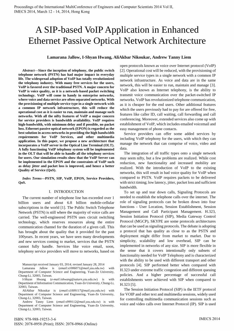
The operation of the SIP-VoIP component is given in
Figure 5. It is separated into two parts, where the public part
can be accessed by the public users, and the private part which
can only be accessed by the authorized users. The SIP
Load-Balancer is used for protecting the underlying elements
of the SIP server. As the name implies is can also be used as a
load balancer if the system is scaled to more than just one pair
of servers. SIP Proxy/Registrar is the busy bee of the SIP
server. It handles user registrations, the authentication of end
points. The Proxy Server also knows the location of Callee if a
call is made to certain number, and check if it is in the same
domain or else send it to the right proxy Server. SIP Back to
Fig. 2. ONU flowchart
Fig. 3. Detailed ONU structure
Fig. 4. Detailed OLT structure
Proceedings of the International MultiConference of Engineers and Computer Scientists 2014 Vol II, IMECS 2014, March 12 - 14, 2014, Hong Kong
ISBN: 978-988-19253-3-6 ISSN: 2078-0958 (Print); ISSN: 2078-0966 (Online)
IMECS 2014
Back User Agent (B2BUA) uncouples the call-leg 1 (i.e. from
the caller to the SIP Server) from call-leg 2 (which is from the
SIP server to the callee). It also does topology hiding; it hides
caller information where necessary, and outbound
authentication. The SIP App-Server will be used for other
voice applications like voicemail, and can also be used for
reminder calls. The Media Relay is controlled by the SIP
proxy. After the calls are authenticated and connected the
media relay is called on for packet relay.
C. VoIP Dynamic Bandwidth Allocation (VoIP-DBA)
A new DBA is proposed called VoIP-DBA, which is
designed to handle traffic allocation. When the OLT receives
the REPORT message, it identifies the four different queues.
The VoIP-DBA first checks its available bandwidth and the
required bandwidth for the voip request and allocates all the
requested bandwidth by the voip traffic. The VoIP-DBA then
checks its remaining bandwidth and allocates bandwidth to
the EF traffic as indicated by the report. After the voip and EF
traffic has been allocated bandwidth it checks its remaining
bandwidth and allocates the bandwidth to the requested AF
traffic, and if there is any remaining bandwidth, then the BE
traffic will also be allocated. In this case, priority is given to
Voip then EF then AF and last is BE. The buffer manager
which usually uses FIFO by the OLT for downstream
transmission is redesigned to a priority queuing mechanism,
and the highest priority is always given to the VoIP packets,
followed by EF then AF and BE.
D. VoIP call handling.
One of the most important functions in VoIP is the INVITE
function. The INVITE is a SIP method that specifies the
action that the requester (Calling Party) wants the server
(Called Party) to take. The INVITE request contains a number
of header fields. Header fields are named attributes that
provide additional information about a message. The ones
present in an INVITE include a unique identifier for the call,
the destination address, Calling Party Address, and
information about the type of session that the requester wishes
to establish with the server.
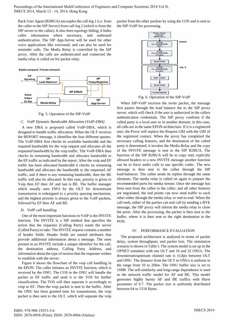
Figure 6 shows the flowchart of the voip call handling in
the EPON. The caller initiates an INVITE function, which is
received by the ONU. The COS in the ONU will handle the
packet as EF traffic and send it to the TOS for further
classification. The TOS will then separate it accordingly to
voip or EF. Then the voip packet is sent to the buffer. After
the ONU has been granted time for transmission, the voip
packet is then sent to the OLT, which will separate the voip
packet from the other packets by using the COS and is sent to
the SIP-VoIP for processing.
When SIP-VoIP receives the invite packet, the message
first passes through the load balance the to the SIP proxy
server, which will check if the user is authorized in the callers
authentication credentials. The SIP proxy confirms if the
called party is a local user or in another domain; in this case,
all calls are in the same EPON architecture. If it is a registered
user, the Proxy will replace the Request URI with the URI of
the registered contact. When the proxy has completed the
necessary calling features, and the destination of the called
party is determined, it invokes the Media Relay and the copy
of the INVITE message is sent to the SIP B2BUA. The
function of the SIP B2BUA will be to copy only explicitly
allowed headers to a new INVITE message another function
can be to force audio calls to use specific codec. The new
message is then sent to the callee through the SIP
load-balancer. The callee sends its replies through the same
elements. The media relay is called on again to prepare the
recommended ports for media stream. Once the message has
been sent from the callee to the caller, and all other features
are negotiated, the end points can now send traffic to each
other either through the media relay or end-to-end. When the
call ends, either of the parties can end call by sending a BYE
message, the SIP proxy will inform the media relay to close
the ports. After the processing, the packet is then sent to the
buffer, where it is then sent to the right destination in the
PON.
IV. PERFORMANCE EVALUATION
The proposed architecture is analyzed in terms of packet
delay, system throughputs, and packet loss. The simulation
scenario is shown in Table I. The system model is set up in the
OPNET simulator with one OLT and 16 and 32 ONUs. The
downstream/upstream channel rate is 1Gbps between OLT
and ONU. The distance from the OLT to ONUs is uniform in
the range from 10 to 20km. The ONU buffer size is set to
10Mb. The self-similarity and long-range dependence is used
as the network traffic model for AF and BE. This model
generates highly bursty AF and BE traffics with Hurst
parameter of 0.7. The packet size is uniformly distributed
between 64 to 1518 Bytes.
Fig. 6. Operation of the SIP-VoIP
Fig. 5. Operation of the SIP-VoIP
Proceedings of the International MultiConference of Engineers and Computer Scientists 2014 Vol II, IMECS 2014, March 12 - 14, 2014, Hong Kong
ISBN: 978-988-19253-3-6 ISSN: 2078-0958 (Print); ISSN: 2078-0966 (Online)
IMECS 2014
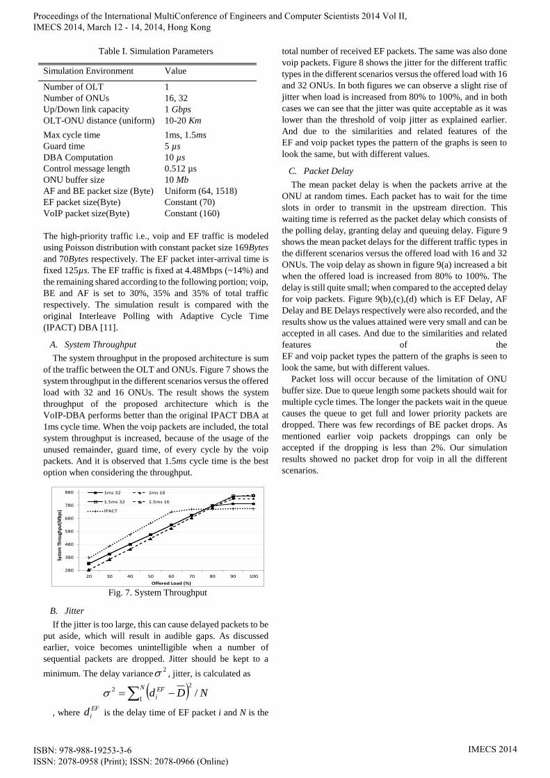
Table I. Simulation Parameters
The high-priority traffic i.e., voip and EF traffic is modeled
using Poisson distribution with constant packet size 169Bytes
and 70Bytes respectively. The EF packet inter-arrival time is
fixed 125µs. The EF traffic is fixed at 4.48Mbps (~14%) and
the remaining shared according to the following portion; voip,
BE and AF is set to 30%, 35% and 35% of total traffic
respectively. The simulation result is compared with the
original Interleave Polling with Adaptive Cycle Time
(IPACT) DBA [11].
A. System Throughput
The system throughput in the proposed architecture is sum
of the traffic between the OLT and ONUs. Figure 7 shows the
system throughput in the different scenarios versus the offered
load with 32 and 16 ONUs. The result shows the system
throughput of the proposed architecture which is the
VoIP-DBA performs better than the original IPACT DBA at
1ms cycle time. When the voip packets are included, the total
system throughput is increased, because of the usage of the
unused remainder, guard time, of every cycle by the voip
packets. And it is observed that 1.5ms cycle time is the best
option when considering the throughput.
B. Jitter
If the jitter is too large, this can cause delayed packets to be
put aside, which will result in audible gaps. As discussed
earlier, voice becomes unintelligible when a number of
sequential packets are dropped. Jitter should be kept to a
minimum. The delay variance2 , jitter, is calculated as
NDdN EF
i /2
1
2
, where EF
id is the delay time of EF packet i and N is the
total number of received EF packets. The same was also done
voip packets. Figure 8 shows the jitter for the different traffic
types in the different scenarios versus the offered load with 16
and 32 ONUs. In both figures we can observe a slight rise of
jitter when load is increased from 80% to 100%, and in both
cases we can see that the jitter was quite acceptable as it was
lower than the threshold of voip jitter as explained earlier.
And due to the similarities and related features of the
EF and voip packet types the pattern of the graphs is seen to
look the same, but with different values.
C. Packet Delay
The mean packet delay is when the packets arrive at the
ONU at random times. Each packet has to wait for the time
slots in order to transmit in the upstream direction. This
waiting time is referred as the packet delay which consists of
the polling delay, granting delay and queuing delay. Figure 9
shows the mean packet delays for the different traffic types in
the different scenarios versus the offered load with 16 and 32
ONUs. The voip delay as shown in figure 9(a) increased a bit
when the offered load is increased from 80% to 100%. The
delay is still quite small; when compared to the accepted delay
for voip packets. Figure 9(b),(c),(d) which is EF Delay, AF
Delay and BE Delays respectively were also recorded, and the
results show us the values attained were very small and can be
accepted in all cases. And due to the similarities and related
features of the
EF and voip packet types the pattern of the graphs is seen to
look the same, but with different values.
Packet loss will occur because of the limitation of ONU
buffer size. Due to queue length some packets should wait for
multiple cycle times. The longer the packets wait in the queue
causes the queue to get full and lower priority packets are
dropped. There was few recordings of BE packet drops. As
mentioned earlier voip packets droppings can only be
accepted if the dropping is less than 2%. Our simulation
results showed no packet drop for voip in all the different
scenarios.
Simulation Environment Value
Number of OLT 1
Number of ONUs 16, 32
Up/Down link capacity 1 Gbps
OLT-ONU distance (uniform) 10-20 Km
Max cycle time 1ms, 1.5ms
Guard time 5 µs
DBA Computation 10 µs
Control message length 0.512 µs
ONU buffer size 10 Mb
AF and BE packet size (Byte) Uniform (64, 1518)
EF packet size(Byte) Constant (70)
VoIP packet size(Byte) Constant (160)
280
380
480
580
680
780
880
20 30 40 50 60 70 80 90 100
Syst
em T
hrou
ghpu
t(M
bps)
Offered Load (%)
1ms 32 1ms 16
1.5ms 32 1.5ms 16
IPACT
Fig. 7. System Throughput
Proceedings of the International MultiConference of Engineers and Computer Scientists 2014 Vol II, IMECS 2014, March 12 - 14, 2014, Hong Kong
ISBN: 978-988-19253-3-6 ISSN: 2078-0958 (Print); ISSN: 2078-0966 (Online)
IMECS 2014

V. CONCLUSION
With the introduction of the VoIP Server in the OLT, the
packet voip packet processing will be done in the OTL. The
proposed VoIP-DBA will handle the voip packets, and make
sure that the required bandwidth for VoIP service is satisfied.
This will eliminate the usual delay that occurs when VoIP
servers are located outside the EPON. The recorded for delay
for voip packets is less than 1ms. The simulation results show
that there were no packet losses for voip and there is the
sufficient amount of bandwidth to handle all VOIP calls. To
decrease cost, network and service providers can incorporate
the SIP-VoIP component in the OLT. This architecture can be
further implemented with multiple PONs. Where in each
VoIP-OLT will act as a proxy server for handling call
redirecting if the called party is not in the same EPON
architecture.
REFERENCES
[1] Available online: http://www.itu.int/en/ITU-D/Statistics/Pages/stat/
default.aspx.
[2] P.V. Mockapetris, “Telephony's next act,” IEEE Spectrum, vol. 43,
issue. 4, pp. 28-32, April 2006.
[3] K. Salah, “On the deployment of VoIP in Ethernet networks:
methodology and case study,” Computer Communications, vol. 29,
issue 8, pp. 1039-1054, May 2006.
[4] I. Basicevic, M. Popovic and D. Kukolj, “Comparison of SIP and
H.323 Protocols,” in The Third International Conference on Digital
Telecommunications, pp.162-167, 2008.
[5] B.S. De, P.P. Joshi, V. Sahdev and D. Callahan, “End-to-end voice
over IP testing and the effects of QoS on signaling”, in Proceedings of
the 35th Southeastern Symposium on System Theory Morgantown, pp.
142–147, 2003.
[6] Available online: http://www.sipwise.com/doc/2.8/handbook-ce.pdf.
[7] I.S. Hwang, A. Nikoukar, C.H. Teng and K.R. Lai, “Scalable
Architecture for VOD Service Enhancement Based on a Cache Scheme
in an Ethernet Passive Optical Network,” Journal of Optical
Communication and Networking, vol. 5, issue. 4, pp. 271-282, 2013.
[8] J.S. Li, H.C. Kao and W.H. Lin, “Achieving maximal VoIP calls in
802.11 wireless networks,” Computer Communications, vol. 33, issue.
11, pp. 1296-1303, July 2010.
[9] G. Wu, D. Liu, Y. Chang, and C. Zhang “The implementation of TDM
service in EPON system,” in SPIE 6784 Network Architectures,
Management, and Applications V, 67843J, 2007, doi:10.1117/
12.743418.
[10] S. Sharafeddine, A. Riedl, J. Glasmann and J. Totzke, “On traffic
characteristics and bandwidth requirements of voice over IP
applications,” in Eighth IEEE International Symposium on Computers
and Communication, pp.1324-1330, 2003.
[11] L. Cai, Y. Xiao, X. Shen and J.W. Mark, “VoIP over WLAN: Voice
capacity, admission control, QoS, and MAC,” International Journal of
Communication Systems, Vol. 19, issue. 15, pp. 491-508, 2006.
[12] G. Kramer, B. Mukherjee; G. Pesavento, “IPACT a dynamic protocol
for an Ethernet PON (EPON),” IEEE Communications Magazine, vol.
40, issue. 2, pp. 74-80, 2002.
0
0.2
0.4
0.6
0.8
1
1.2
20 30 40 50 60 70 80 90 100
VoIP
Jitt
er
Offered Load (%)
1ms 32 1ms 16
1.5ms 32 1.5ms 16
0
0.2
0.4
0.6
0.8
1
1.2
20 30 40 50 60 70 80 90 100
EF Ji
tter
Offered Load (%)
1ms 32 1ms 16
1.5ms 32 1.5ms 16
(a) (b)
Fig. 8: VoIP Jitter
(b)
0
0.002
0.004
0.006
0.008
0.01
0.012
0.014
20 30 40 50 60 70 80 90 100
AF D
elay
(ms)
Offered Load (%)
1ms 32 1ms 16
1.5ms 32 1.5ms 16
(c) (d)
Fig. 9: Delays
(a)
Proceedings of the International MultiConference of Engineers and Computer Scientists 2014 Vol II, IMECS 2014, March 12 - 14, 2014, Hong Kong
ISBN: 978-988-19253-3-6 ISSN: 2078-0958 (Print); ISSN: 2078-0966 (Online)
IMECS 2014