a single phase active device for power quality improvement ... · page 1704 a single phase active...
TRANSCRIPT

Page 1704
A Single Phase Active Device for Power Quality Improvement of
Electrified Transportation
K.Devasree
M.Tech,
Arjun College of Technology & Science.
Rosaiah Mudigondla
Assistant Professor,
Arjun College of Technology & Science.
ABSTRACT:
A transformer less half breed arrangement dynamic
filter is proposed to upgrade the force quality in single-
stage frameworks with basic burdens. This paper helps
the vitality administration and force quality issues
identified with electric transportation and spotlights on
enhancing electric vehicle load association with the
matrix. The control system is de-marked to avoid
current symphonious bends of nonlinear burdens to
stream into the utility and adjusts the force component
of this later. While shielding delicate burdens from
voltage unsettling influences, lists, and swells started
by the force sys-tem, ridded of the arrangement
transformer, the setup is profitable for a mechanical
execution. This polyvalent half breed topology
permitting the consonant disconnection and pay of
voltage mutilations could assimilate or infuse the
helper energy to the matrix. Beside useful
examination, this paper likewise explores on the
impact of additions and postponements in the
continuous controller dependability. The reenactments
and test comes about displayed in this paper were done
on a 2-kVA research center model exhibiting the
viability of the proposed topology.
Index Terms:
Current harmonics, electric vehicle, hybridseries active
filter (HSeAF), power quality, real-time control.
I. INTRODUCTION:
The estimate of future Smart Grids connected with
electric vehicle charging stations has made a genuine
worry on all parts of force nature of the force
framework; while across the board electric vehicle
battery charging units [1], [2] effectsly affect power
dispersion framework consonant volt-age levels [3].
Then again, the development of sounds nourished from
nonlinear burdens like electric vehicle drive battery
chargers [4], [5], which without a doubt impactsly
affect the force framework and influence plant gear,
ought to be considered in the advancement of present
day networks. Similarly, the expanded rms and
pinnacle estimation of the contorted current
waveforms increment warming and misfortunes and
cause the disappointment of the electrical gear. Such
marvel viably decreases framework proficiency and
ought to have legitimately been tended to [6], [7].
Also, to ensure the purpose of regular coupling (PCC)
from voltage bends, utilizing a dynamic voltage
restorer (DVR) capacity is prompted. An answer is to
lessen the contamination of force hardware based loads
specifically at their source. Albeit a few endeavors are
made for a particular contextual investigation, a bland
arrangement is to be investigated. There exist two sorts
of dynamic force gadgets to defeat the portrayed force
quality issues. The main class are arrangement
dynamic channels (SeAFs), including half and half sort
ones. They were created to dispense with current
music delivered by nonlinear burden from the force
framework. SeAFs are less scattered than the shunt
sort of dynamic channels [8], [9]. The upside of the
SeAF contrasted with the shunt sort is the sub-par
rating of the compensator versus the heap ostensible
rating [10].

Page 1705
In any case, the unpredictability of the design and need
of a disengagement arrangement transformer had
decelerated their modern application in the circulation
framework. The second classification was produced in
worry of tending to voltage issues on touchy burdens.
Generally known as DVR, they have a comparative
arrangement as the SeAF. These two classifications are
not the same as each other in their control standard.
This distinction depends on the motivation behind their
application in the framework. The cross breed
arrangement dynamic channel (HSeAF) was proposed
to address the previously mentioned issues with one
and only blend. Theoretically, they are fit to repay
current sounds, guaranteeing a force element (PF)
rectification and dispensing with voltage mutilations at
the PCC [11], [12]. These properties make it a fitting
possibility for force quality ventures. The three-stage
SeAFs are very much recorded [13], [14], though
restricted examination works reported the single-stage
utilizations of SeAFs in the writing. In this paper, a
solitary stage transformer less HSeAF is proposed and
fit for tidying up the network side association transport
bar from flow music produced by a nonlinear burden
[15].
With a littler rating up to 10%, it could without much
of a stretch supplant the shunt dynamic channel [16].
Moreover, it could reestablish a sinusoidal voltage at
the heap PCC. The upside of the proposed design is
that non-straight symphonious voltage and current
delivering burdens could be adequately adjusted. The
transformer less cross breed arrangement dynamic
channel (THSeAF) is an option alternative to
traditional force moving converters in circulated era
frameworks with high infiltration of renewable vitality
sources, where every stage can be controlled
independently and could be worked autonomously of
different stages [17]. This paper demonstrates that the
division of a three-stage converter into single-stage H-
span converters has permitted the disposal of the
unreasonable detachment transformer and advances
modern application for sifting purposes. The setup has
demonstrated extraordinary capacity to perform asked
for remunerating undertakings for the redress of
current and voltage twists, PF revision, and voltage
rebuilding on the heap terminal [18]. This paper is
composed as takes after. The framework design is
presented in the accompanying area. At that point, the
operation guideline of the proposed setup is clarified.
The third segment is committed to the demonstrating
and investigation of the control calculation executed in
this work. The dc voltage direction and its
contemplations are quickly clarified, and the voltage
and current symphonious identification technique is
expressly portrayed. To assess the setup and the
control approach, a few situations are reenacted. Trial
comes about performed in the research center are
shown to accept recreations. This paper is outlined
with a conclusion and addendum where further
scientific advancements are illustrated.
II. SYSTEM ARCHITECTURE:
A. System Configuration
The THSeAF appeared in Fig. 1 is made out of a H-
span converter associated in arrangement between the
source and the heap. A shunt uninvolved capacitor
guarantees a low impedance way for current music. A
dc assistant source could be associated with infuse
power amid voltage hangs. The dc-join vitality storage
system is described in [19].
Fig. 1. (a) Schematic of a single-phase smart load
with the compensator installation. (b) Electrical
diagram of the THSeAF in a single-phase utility.

Page 1706
The framework is actualized for an evaluated force of
2200 VA. To guarantee a quick transient reaction with
adequate soundness edges over an extensive variety of
operation, the controller is executed on a
dSPACE/dsp1103. The framework parameters are
recognized in Table I. A variable wellspring of 120
Vrms is associated with a 1.1-kVA nonlinear burden
and a 998-VA straight load with a 0.46 PF. The
THSeAF is associated in arrangement keeping in mind
the end goal to infuse the remunerating voltage. On the
dc side of the compensator, an assistant dc-join vitality
stockpiling framework is introduced. Comparable
parameters are likewise connected for commonsense
usage. HSeAFs are frequently used to remunerate
twists of the ebb and flow kind of nonlinear burdens.
Case in point, the misshaped current and voltage
waveforms of the nonlinear framework amid typical
operation and when the source voltage got to be
twisted are delineated in Fig. 2.
The THSeAF is avoided, and ebb and flow music
streamed specifically into the network. As one can see,
notwithstanding amid typical operation, the present
music (with an aggregate symphonious contortion
(THD) of 12%) mutilate the PCC, bringing about a
voltage THD of 3.2%. The conduct of the framework
when the network is exceedingly contaminated with
19.2% of THD is additionally delineated. The
proposed arrangement could be exclusively associated
with the framework with no need of a massive and
excessive arrangement infusion transformer, making
this topology equipped for remunerating source current
sounds and voltage contortion at the PCC
Fig. 2.Terminal voltage and current waveforms of
the 2-kVA single-phase system without
compensator. (a) Regular operation. (b) Grid’s
voltage distortion (scales: 50 V/div for channel 1
and 10 A/div for channel 2).
TABLE I: CONFIGURATION PARAMETERS
Regardless of the fact that the quantity of switches has
expanded, the transformer less arrangement is more
financially savvy than some other arrangement
compensators, which for the most part uses a
transformer to infuse the remuneration voltage to the
force network. The upgraded aloof channel is made out
of fifth, seventh, and high-pass channels. The latent
channel ought to be balanced for the framework upon
burden and government directions.
A correlation between various existing designs is given
in Table II. It is meant to call attention to the focal
points and detriments of the proposed arrangement
over the routine topologies. To stress the examination
table decently, the identical single period of every
design is considered in the assessment. Money related
creation assessment exhibited a 45% diminishment in
segment costs and impressive lessening in get together
terms too.
Page 1707
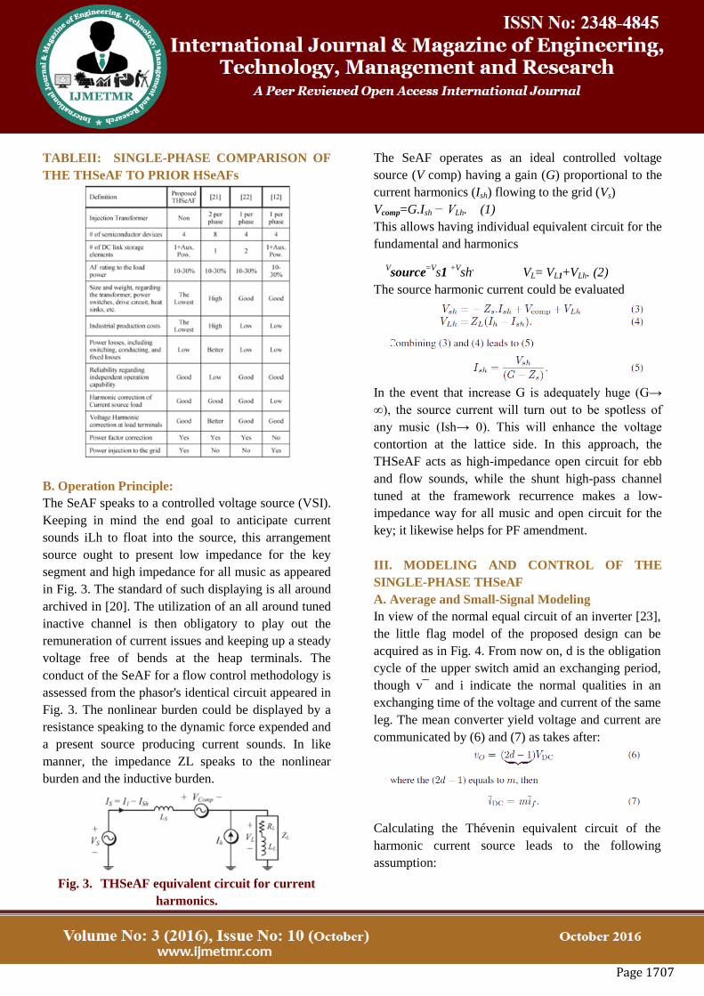
TABLEII: SINGLE-PHASE COMPARISON OF
THE THSeAF TO PRIOR HSeAFs
B. Operation Principle:
The SeAF speaks to a controlled voltage source (VSI).
Keeping in mind the end goal to anticipate current
sounds iLh to float into the source, this arrangement
source ought to present low impedance for the key
segment and high impedance for all music as appeared
in Fig. 3. The standard of such displaying is all around
archived in [20]. The utilization of an all around tuned
inactive channel is then obligatory to play out the
remuneration of current issues and keeping up a steady
voltage free of bends at the heap terminals. The
conduct of the SeAF for a flow control methodology is
assessed from the phasor's identical circuit appeared in
Fig. 3. The nonlinear burden could be displayed by a
resistance speaking to the dynamic force expended and
a present source producing current sounds. In like
manner, the impedance ZL speaks to the nonlinear
burden and the inductive burden.
Fig. 3. THSeAF equivalent circuit for current
harmonics.
The SeAF operates as an ideal controlled voltage
source (V comp) having a gain (G) proportional to the
current harmonics (Ish) flowing to the grid (Vs)
Vcomp=G.Ish − VLh. (1)
This allows having individual equivalent circuit for the
fundamental and harmonics
Vsource
=Vs1
+Vsh
, VL= VL1+VLh. (2)
The source harmonic current could be evaluated
In the event that increase G is adequately huge (G→
∞), the source current will turn out to be spotless of
any music (Ish→ 0). This will enhance the voltage
contortion at the lattice side. In this approach, the
THSeAF acts as high-impedance open circuit for ebb
and flow sounds, while the shunt high-pass channel
tuned at the framework recurrence makes a low-
impedance way for all music and open circuit for the
key; it likewise helps for PF amendment.
III. MODELING AND CONTROL OF THE
SINGLE-PHASE THSeAF
A. Average and Small-Signal Modeling
In view of the normal equal circuit of an inverter [23],
the little flag model of the proposed design can be
acquired as in Fig. 4. From now on, d is the obligation
cycle of the upper switch amid an exchanging period,
though v¯ and i indicate the normal qualities in an
exchanging time of the voltage and current of the same
leg. The mean converter yield voltage and current are
communicated by (6) and (7) as takes after:
Calculating the Thévenin equivalent circuit of the
harmonic current source leads to the following
assumption:

Page 1708
If the harmonic frequency is high enough, it is possible
to assume that there will be no voltage harmonics
across the load. The state-space small-signal ac model
could be derived by a linear zed perturbation of the
averaged model as follows
By means of (10) and (12), the state-space
representation of the model is obtained as shown in
Fig. 4.
Fig. 4. Small-signal model of
transformerlessHSeAF in series be-tween the grid
and the load.
The exchange capacity of the repaying voltage versus
the heap voltage, TV_CL(s), and the source current,
TCI (s), are produced in the Appendix. In the interim,
to control the dynamic part freely, the inferred
exchange capacity ought to be self-ruling from the
framework design. The exchange capacity TV m
presents the connection between the yield voltages of
the converter versus the obligation cycle of the
principal leg converter's upper switch
The further point by point inference of unfaltering
state exchange capacities is depicted in Section V. A
dc assistant source ought to be utilized to keep up a
satisfactory supply on the heap terminals. Amid the
droop or swell conditions, it ought to retain or infuse
energy to keep the voltage size at the heap terminals
inside a predetermined edge. In any case, if the pay of
lists and swells is less basic, a capacitor could be sent.
Thus, the dc-join voltage over the capacitor ought to
be directed as exhibited in Fig. 5.
Fig. 5. Control system scheme of the active part.
B. Voltage and Current Harmonic Detection
The external circle controller is utilized where a
capacitor replaces the dc assistant source. This control
methodology is all around clarified in the past area.
The inward circle control technique depends on a
circuitous control rule. A quick Fourier change was
utilized to separate the greatness of the crucial and its
stage degree from current music. The control pick up
G speaking to the impedance of the hotspot for current
sounds has an adequate level to clean the framework
from current music encouraged through the nonlinear
burden. The second relative integrator (PI) controller
utilized as a part of the external circle was to upgrade
the adequacy of the controller when directing the dc
transport. Hence, a more precise and quicker transient
reaction was accomplished without trading off the pay
conduct of the framework.

Page 1709
As per the hypothesis, the addition G ought to be kept
in a reasonable level, keeping the sounds from
streaming into the matrix [22], [24]. As beforehand
talked about, for a more exact remuneration of current
sounds, the voltage music ought to likewise be
considered. The repaying voltage for current
symphonious remuneration is acquired from
Thus, as voltage mutilation at the heap terminals is not
craved, the voltage hang and swell ought to likewise
be explored in the internal circle. The shut circle
condition (16) permits to in a roundabout way keeping
up the voltage size at the heap side equivalent to VL∗
as a predefined esteem, inside adequate edges
vcomp_v=vˆL − VL∗sin(ωS t). (16)
The whole control plan for the THSeAF introduced in
Fig. 5 was utilized and actualized as a part of
MATLAB/Simulink for continuous reproductions and
the computation of the repaying voltage. The constant
tool kit of dSPACE was utilized for gathering and
execution on the dsp-1103 control board. The source
and load voltages, together with the source current, are
considered as framework information signals. As per
Srianthumronget al. [25], a circuitous control builds
the dependability of the framework. The source current
harmonics are obtained by extracting the fundamental
component from the source current
v∗_=vcomp_v − vcomp_i+vDC_ref(17)
Where the vDC_ref is the voltage required to maintain
the dc bus voltage constant
vDC_ref(t) = VO_DC · sin (ωS t). (18)
A stage bolted circle was utilized to get the reference
rakish recurrence (ωs). Appropriately, the extricated
current symphonious contains a crucial segment
synchronized with the source voltage in request to
amend the PF. This current speaks to the responsive
force of the heap.
The addition G speaking to the resistance for sounds
changes over current into a relative voltage. The
created reference voltage vcomp_i required to clean
the source current from music is depicted in (15). As
per the displayed recognition calculation, the
remunerated reference voltage v∗Comp_ref is
computed. From there on, the reference sign is
contrasted and the deliberate yield voltage and
connected to a PI controller to produce the comparing
door signals as in Fig. 6.
Fig. 6. Block diagram of THSeAF and PI
controller.
C. Stability Analysis for Voltage and Current
Harmonics:
The security of the arrangement is for the most part
influenced by the presented deferral of a computerized
controller. This segment considers the effect of the
deferral first on the comprehensive remunerated
framework as indicated by works refered to in the
writing. From that point, its consequences for the
dynamic compensator are isolated from the matrix.
Utilizing absolutely inductive source impedance (see
Fig. 4) and Kirchhoff's law for consonant recurrence
segments, (19) is determined. The deferral time of the
advanced controller, extensive increase G, and the high
firmness of the framework truly influence the security
of the shut circle controlled framework.
The compensating voltage including the delay time
generated by the THSeAF in the Laplace domain [see
(1)] is
Page 1710
Considering (19) and (20), the control diagram of the
system with delay is obtained as in Fig. 7.
Fig. 7. Control diagram of the system with delay.
Fig. 8.Closed-loop control diagram of the active
filter with a constant delay time τ.
For the sake of simplicity, the overall delay of the
system is assumed to be a constant value τ. Therefore,
the open-loop transfer function is obtained
From the Nyquist stability criterion, the stable
operation of the system must satisfy the following
condition:
A system with a typical source inductance Ls of 250
μH and a delay of 40 μs is considered stable according
to (22) when the gain G is smaller than 10Ω.
Experimental results confirm the stability of the
system presented in this paper. Moreover, the
influence of the delay on the control algorithm should
also be investigated. According to the transfer
functions (13) and (14), the control of the active part is
affected by the delay introduce by the digital
controller. Thus, assuming an ideal switching
characteristic for the IGBTs, the closed-loop system
for the active part controller is shown in Fig. 8.The
open-loop transfer function in Fig. 8 turns to (23),
where the τ is the delay time initiated by the digital
controller
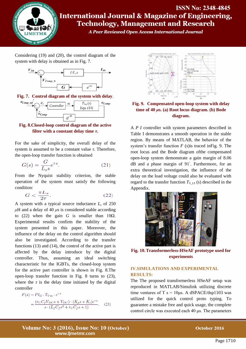
Fig. 9. Compensated open-loop system with delay
time of 40 μs. (a) Root locus diagram. (b) Bode
diagram.
A P I controller with system parameters described in
Table I demonstrates a smooth operation in the stable
region. By means of MATLAB, the behavior of the
system’s transfer function F (s)is traced inFig. 9. The
root locus and the Bode diagram ofthe compensated
open-loop system demonstrate a gain margin of 8.06
dB and a phase margin of 91◦. Furthermore, for an
extra theoretical investigation, the influence of the
delay on the load voltage could also be evaluated with
regard to the transfer function TV_LS (s) described in the
Appendix.
Fig. 10. Transformerless-HSeAF prototype used for
experiments
IV.SIMULATIONS AND EXPERIMENTAL
RESULTS:
The The proposed transformerless HSeAF setup was
reproduced in MATLAB/Simulink utilizing discrete
time ventures of T s = 10μs. A dSPACE/dsp1103 was
utilized for the quick control proto typing. To
guarantee a mistake free and quick usage, the complete
control circle was executed each 40 μs. The parameters
Page 1711
are recognized in Table I. The blend of a solitary stage
nonlinear burden and a direct load with an aggregate
appraised force of 2 kVA with a 0.74 slacking PF is
connected for research facility trials and reproductions.
For examinations and reenactments, a 2-kVA 120-
Vrms 60-Hz variable source is utilized. THSeAF
associated in arrangement to the framework repays the
momentum sounds and voltage mutilations. The
complete test framework is exhibited in Fig. 10. An
increase G = 8 Ω identical to 1.9 p.u. was utilized to
control current music. As specified before, the capacity
of operation with low dc voltage is considered as one
of the fundamental focal points of the proposed setup.
For this analysis, it is kept up at 130 Vdc. Amid a
matrix's voltage bending, the compensator directs the
heap voltage size, repays current music, and amends
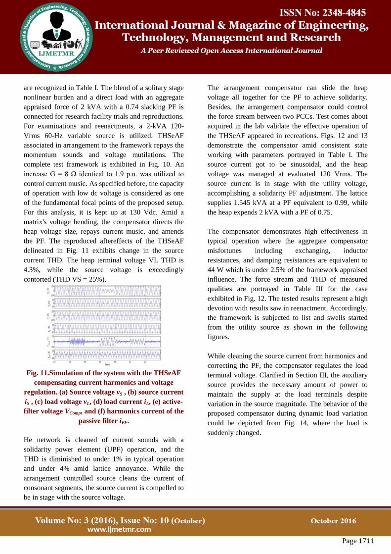
the PF. The reproduced aftereffects of the THSeAF
delineated in Fig. 11 exhibits change in the source
current THD. The heap terminal voltage VL THD is
4.3%, while the source voltage is exceedingly
contorted (THD VS = 25%).
Fig. 11.Simulation of the system with the THSeAF
compensating current harmonics and voltage
regulation. (a) Source voltage vS , (b) source current
iS , (c) load voltage vL, (d) load current iL, (e) active-
filter voltage VComp, and (f) harmonics current of the
passive filter iPF.
He network is cleaned of current sounds with a
solidarity power element (UPF) operation, and the
THD is diminished to under 1% in typical operation
and under 4% amid lattice annoyance. While the
arrangement controlled source cleans the current of
consonant segments, the source current is compelled to
be in stage with the source voltage.
The arrangement compensator can slide the heap
voltage all together for the PF to achieve solidarity.
Besides, the arrangement compensator could control
the force stream between two PCCs. Test comes about
acquired in the lab validate the effective operation of
the THSeAF appeared in recreations. Figs. 12 and 13
demonstrate the compensator amid consistent state
working with parameters portrayed in Table I. The
source current got to be sinusoidal, and the heap
voltage was managed at evaluated 120 Vrms. The
source current is in stage with the utility voltage,
accomplishing a solidarity PF adjustment. The lattice
supplies 1.545 kVA at a PF equivalent to 0.99, while
the heap expends 2 kVA with a PF of 0.75.
The compensator demonstrates high effectiveness in
typical operation where the aggregate compensator
misfortunes including exchanging, inductor
resistances, and damping resistances are equivalent to
44 W which is under 2.5% of the framework appraised
influence. The force stream and THD of measured
qualities are portrayed in Table III for the case
exhibited in Fig. 12. The tested results represent a high
devotion with results saw in reenactment. Accordingly,
the framework is subjected to list and swells started
from the utility source as shown in the following
figures.
While cleaning the source current from harmonics and
correcting the PF, the compensator regulates the load
terminal voltage. Clarified in Section III, the auxiliary
source provides the necessary amount of power to
maintain the supply at the load terminals despite
variation in the source magnitude. The behavior of the
proposed compensator during dynamic load variation
could be depicted from Fig. 14, where the load is
suddenly changed.

Page 1712
Fig. 13.Waveforms during a variation of the source
voltage. (a) SourcevoltagevS [50 V/div], (b) source
current iS [10 A/div], (c) load PCC voltage vL [50
V/div], and (d) load current iL [10 A/div.
TABLE.III. LABORATORY MEASURED
VALUE AND POWER FLOW ANALYSIS
The experimented results illustrate a high fidelity with
results observed in simulation. Therefore, the system is
subjected to sag and swells initiated from the utility
source as shown in the following figures. While
cleaning the source current from harmonics and
correcting the PF, the compensator regulates the load
terminal voltage.
Clarified in Section III, the auxiliary source provides
the necessary amount of power to maintain the supply
at the load terminals despite variation in the source
magnitude. The behavior of the proposed compensator
during dynamic load variation could be depicted from
Fig. 14, where the load is suddenly changed.
Fig. 14.Waveforms during a dynamic load
variation. (a) Source volt-age vS [50 V/div], (b)
source current iS [10 A/div], (c) load PCC voltage
vL[50 V/div], and (d) load currentiL[10 A/div].
Amid voltage droop and swell, the assistant source
supplies the distinction of energy to keep up the extent
of the heap side voltage controlled. The consonant
substance and THD element of the source utility and
burden PCC introduced show emotional.
Fig. 15.Experimental waveforms under utility
voltage distortion andprolonged sags. (a) Utility
source voltage vS [50 V/div], (b) utility current iS[10
A/div], (c) load PCC voltagevL[50 V/div], and (d)
load currentiL[10 A/div].
Upgrades in THD, while the heap draws dirtied
mongrel rent waveforms. Besides, in spite of the fact
that the network's voltage is contaminated, the
compensator in a mixture approach controls and keeps
up a consonant free load voltage.
V. SUMMARY:
In this paper, a transformerlessHSeAF for force quality
change was created and tried.

Page 1713
The paper highlighted the way that, with the ever
increment of nonlinear burdens and higher exigency of
the buyer for a dependable supply, solid moves ought
to be made into thought for future keen frameworks
keeping in mind the end goal to easily incorporate
electric auto battery chargers to the matrix. The key
oddity of the proposed arrangement is that the
proposed design could enhance the force nature of the
framework in a more broad manner by remunerating
an extensive variety of sounds ebb and flow, despite
the fact that it can be seen that the THSeAF directs and
enhances the PCC voltage. Associated with a
renewable assistant source, the topology can balance
effectively to the force stream in the framework. This
vital capacity is required to guarantee a steady supply
for basic burdens. Acting as high-consonant
impedance, it cleans the force framework and
guarantees a solidarity PF.
The hypothetical demonstrating of the proposed setup
was explored. The proposed transformerless design
was mimicked and tentatively approved. It was shown
that this dynamic compensator reacts legitimately to
source voltage varieties by giving a steady and
mutilation free supply at burden terminals. Moreover,
it wipes out source symphonious streams and enhances
the force nature of the framework without the standard
massive and unreasonable arrangement transformer.
REFERENCES:
[1] L. Jun-Young and C. Hyung-Jun, “6.6-kW onboard
charger design usingDCM PFC converter with
harmonic modulation technique and two-stage dc/dc
converter,” IEEE Trans. Ind. Electron., vol. 61, no. 3,
pp. 1243–1252, Mar. 2014.
[2] R. Seung-Hee, K. Dong-Hee, K. Min-Jung, K.
Jong-Soo, and L. Byoung-Kuk, “Adjustable frequency
duty-cycle hybrid control strategy for fullbridgeseries
resonant converters in electric vehicle chargers,”
IEEETrans. Ind. Electron., vol. 61, no. 10, pp. 5354–
5362, Oct. 2014.
[3] P. T. Staats, W. M. Grady, A. Arapostathis, and R.
S. Thallam, “A statisticalanalysis of the effect of
electric vehicle battery charging on distribution system
harmonic voltages,” IEEE Trans. Power Del., vol. 13,
no. 2,pp. 640–646, Apr. 1998.
[4] A. Kuperman, U. Levy, J. Goren, A. Zafransky,
and A. Savernin, “Batterycharger for electric vehicle
traction battery switch station,” IEEE Trans. Ind.
Electron., vol. 60, no. 12, pp. 5391–5399, Dec. 2013.
[5] Z. Amjadi and S. S. Williamson, “Modeling,
simulation, control of anadvancedLuo converter for
plug-in hybrid electric vehicle energy-storagesystem,”
IEEE Trans. Veh. Technol., vol. 60, no. 1, pp. 64–75,
Jan. 2011.
[6] H. Akagi and K. Isozaki, “A hybrid active filter for
a three-phase 12-pulsediode rectifier used as the front
end of a medium-voltage motor drive,”IEEE Trans.
Power Del., vol. 27, no. 1, pp. 69–77, Jan. 2012.
[7] A. F. Zobaa, “Optimal multiobjective design of
hybrid active power filtersconsidering a distorted
environment,” IEEE Trans. Ind. Electron., vol. 61, no.
1, pp. 107–114, Jan. 2014.
[8] D. Sixing, L. Jinjun, and L. Jiliang, “Hybrid
cascaded H-bridge converterfor harmonic current
compensation,” IEEE Trans. Power Electron.,vol. 28,
no. 5, pp. 2170–2179, May 2013.
Bibliography:
K.Devasree completed B. Tech in electrical and
electronics engineering from Sridevi women’s
engineering college, Pursuing M.tech in power
systems from Arjun College of Technology &science.
Rosaiah Mudigondla Assistant professor in Arjun
college of Technology & Science M.tech (peed)
Ayyan Technology in 2011-2013 Interested subjects:
Power Electronics, electrical machines & power
systems.