a simple series battery/ultracapacitor drive system …web.mit.edu/first/kart/everpres.pdf1 a simple...
TRANSCRIPT

1
A Simple Series Battery/Ultracapacitor Drive System for Light Vehicles and Educational Demonstration
Fourth International Conference & Exhibitionon Ecological Vehicles and Renewable EnergiesMonte-Carlo, Monaco
March 26, 2009
Shane Colton <[email protected]>Massachusetts Institute of TechologyEdgerton Center Summer Engineering Workshop 2008

2
Edgerton Center Summer Engineering Workshop
• Student-Driven Projects Workshop at MIT• Collaboration of MIT Students and Local High School Students• Blend of Technical Challenge and Educational Experience
Team Members: Ethan Aaron, Costas Akrivoulis, Shane Colton, Ronny Contreras, Max Hill, Kevin Krakauer, David McCarthy, Mike Paresky, Edwin Perez-Clancy, Matt Robertson, Anil Singhal, and Cameron Tenny
2007:

3
2008 S.E.W. Project: “The Cap Kart”
Project Objectives:
• Design, build, and test a small electric vehicle, based on a go-kart, with a combined battery/ultracapacitor energy storage and drive system.
• Create a low-cost system that could be easily implemented in light, DC-drive electric vehicles and possibly expanded to full-size vehicles.
• Employ simple design, modeling, and analysis methods, consistent with the educational motivations of the project.
• Create a test vehicle that is both a reliable experimental platform and a fun educational tool:• Wireless data acquisition. “Drive now, analyze later.”• Retain or improve the level of performance of a typical gas go-kart:

4
Technical Background: Battery/Ultracapacitor Hybrids
Ultracapacitor• Low energy density (by mass,
volume, cost).
• High power density in both directions.
• High cycle life.
Battery• High energy density (by mass,
volume, cost).
• Low power density, especially in charging.
• Low cycle life.
• An optimized (by cost, mass, volume) combination of batteries and ultracapacitors can take advantage of the best characteristics of each1.
• Certain battery chemistries, such as lithium Iron phosphate, make these differences less dramatic.
• Similar optimizations exist with other combinations (fuel cell, flywheels, etc).
1R.M. Sclupbach et. al., “Design methodology of a combined batteryultracapacitor energy storage unit for vehicle power management,” in Proc. Power Electronics Specialist Conference, IEEE, Vol. 1, pp. 88-93, Acapulco, Mexico, 2003.

5
Battery/Ultracapacitor Hybrids: Parallel Methods
Low-CurrentCharge Control
UltracapacitorBankBattery
Bank
High-CurrentDC/DC Converter
TractionMotor
Vb Vc
Vm
Ib Ic
Ib+Ic
Im
bc VV
mmcbc IVIIV )(
Ultracapacitor operating voltage is always greater than battery voltage.
Power sharing by summation of currents.
Regenerative braking charges the ultracapacitor, which can then trickle-charge the battery through the low-current DC/DC converter.
Seen in: A.W. Stienecker, M.A. Flute, and T.A. Stuart, “Improved Battery Charging in an Ultracapacitor–Lead Acid Battery Hybrid Energy Storage System for Mild Hybrid Electric Vehicles,”in Proc. SAE World Congress, Detroit, Michigan, USA, 2006.
6
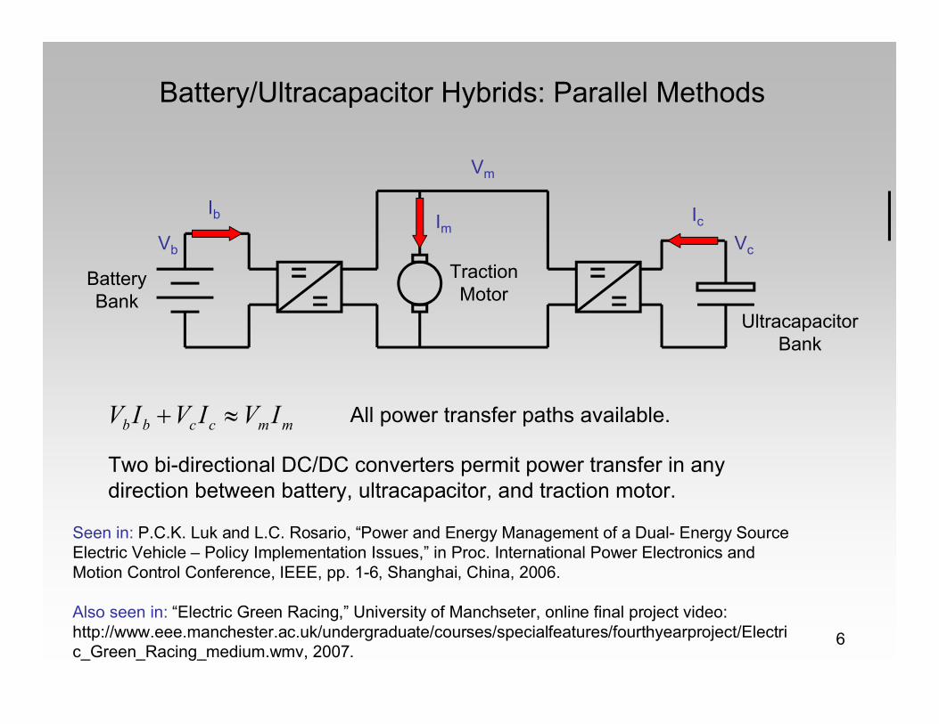
Battery/Ultracapacitor Hybrids: Parallel Methods
UltracapacitorBank
BatteryBank
TractionMotor
Vb Vc
Vm
Ib IcIm
mmccbb IVIVIV All power transfer paths available.
Two bi-directional DC/DC converters permit power transfer in any direction between battery, ultracapacitor, and traction motor.
Seen in: P.C.K. Luk and L.C. Rosario, “Power and Energy Management of a Dual- Energy Source Electric Vehicle – Policy Implementation Issues,” in Proc. International Power Electronics and Motion Control Conference, IEEE, pp. 1-6, Shanghai, China, 2006.
Also seen in: “Electric Green Racing,” University of Manchseter, online final project video: http://www.eee.manchester.ac.uk/undergraduate/courses/specialfeatures/fourthyearproject/Electric_Green_Racing_medium.wmv, 2007.

7
Battery/Ultracapacitor Series Configuration
UltracapacitorBank
BatteryBank
Vb
Vm
Ib Im=Ic
mcmbb IVVIV
Vm-Vc
Power sharing by summation of voltages.
TractionMotor
Voltage present on the ultracapacitor reduces the current demand from the battery at a given motor current demand.
Regenerative braking charges the ultracapacitor only. Switch and bypass diode allow for selective inclusion of ultracapacitor during acceleration.

80V
Vbatt
F1
F2
Standard Separately-Excited Drive
Battery Bank
Separately-ExcitedBrushed DC Motor
Buck Converter (Half-Bridge)
Vout
• Starting-point for our experimental vehicle drive system.
• High-power (300A @ 36V) buck converter for armature.
• Low-power (30A @ 36V) buck converter for field. (Not pictured.)
• Independent field control for “gearing.”

90V
F1
F2
Series Ultracapacitor Modification
Battery Bank
Separately-ExcitedBrushed DC Motor
Ultracapacitor Module
Vout
Vout + Vcap
Vbatt
Buck Converter (Half-Bridge)
• Retain the same power converters.
• Add ultracapacitor module in series with motor.
• Add bypass diode and brake/boost relay.
• Modify control strategy as follows.

100V
Vf
0V
Normal Drive (Capacitor Bypass)
Battery Bank
Separately-ExcitedBrushed DC Motor
Ultracapacitor ModulePWM HIGH:
Vout
Vout + Vcap
Vbatt
Buck Converter (Half-Bridge)
• Battery-only drive, same as standard separately-excited drive.

110V
Vf
0V
Normal Drive (Capacitor Bypass)
Battery Bank
Separately-ExcitedBrushed DC Motor
Ultracapacitor Module
Vout
Vout + Vcap
Vbatt
PWM LOW:Buck Converter
(Half-Bridge)
• Battery-only drive, same as standard separately-excited drive.
120V
Vf
0V
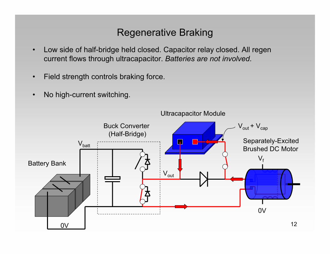
Regenerative Braking
Battery Bank
Separately-ExcitedBrushed DC Motor
Ultracapacitor Module
Vout
Vout + Vcap
Vbatt
Buck Converter (Half-Bridge)
• Low side of half-bridge held closed. Capacitor relay closed. All regen current flows through ultracapacitor. Batteries are not involved.
• Field strength controls braking force.
• No high-current switching.
130V
Vf
0V
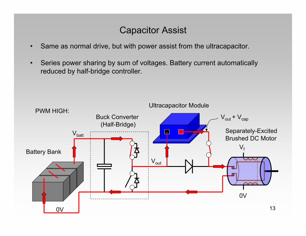
Capacitor Assist
Battery Bank
Separately-ExcitedBrushed DC Motor
Ultracapacitor ModulePWM HIGH:
Vout
Vout + Vcap
Vbatt
Buck Converter (Half-Bridge)
• Same as normal drive, but with power assist from the ultracapacitor.
• Series power sharing by sum of voltages. Battery current automatically reduced by half-bridge controller.

140V
Vf
0V
Capacitor Assist
Battery Bank
Separately-ExcitedBrushed DC Motor
Ultracapacitor Module
Vout
Vout + Vcap
Vbatt
PWM LOW:Buck Converter
(Half-Bridge)
• Same as normal drive, but with power assist from the ultracapacitor.
• Series power sharing by sum of voltages. Battery current automatically reduced by half-bridge controller.

15
Simple Analytical Model
Armature resistance dominates dissipative effects, suggests a simple power conservation approach:

16
Series Power Sharing During Acceleration Assist
Example simulation showing reduced battery load, increased top speed.

17
Series Configuration Attributes
• Smaller ultracapacitor. Entire voltage range used, down to zero volts. Can be significantly lower voltage than the battery.• Decreased cost.• Decreased series resistance.• Easier cell balancing.
• No external inductors. All switched current passes through motorwindings.
• One single-directional DC-DC converter; could be an off-the-shelf DC motor controller. Converter sees fixed battery input voltage.
• No pre-charge circuit required for the ultracapacitor.
• Simpler circuit to model, build, explain, and demonstate, important for the educational objective.
• Disadvanatge: No direct power transfer path between battery and ultracapacitor. All regenerated energy can only be re-used by motor.

18
Vehicle Layout

19
Electric Motor
7kW, 48V Separately-Excited DC Motor

20
Electrical System
300A-peak Motor Controller and Wireless Interface

21
Electrical System
Armature and Field Drive Half-Bridges
Isolators and Optical Couplers

22
Field Control
Electric Sequential “Gear” Shifter

23
Test Drives
(Launch Video)

24
Flywheel Testing
Effective inertial loads up to 250kg.

25
Flywheel Testing
Example regenerative braking profile.

26
Flywheel Testing
Example acceleration assist profile.

27
Flywheel Testing
Capacitor assist on torque-speed and power-speed curves.

28
Conclusions and Future Work
• Series battery/ultracapacitor combination offers several advantages which make it well-suited for light DC-drive vehicles as an efficiency and/or performance enhancement.
• Experimental vehicle confirms the validity of the simple system model: Regenerative braking and capacitor assist efficiency predictable using armature resistance model.
• Simple system makes for an ideal educational project.
Future Work:
• Track testing.
• More work on merging regenerative and mechanical brakes.
• Extension to AC drive system?

29Questions?Questions?
Comments?Comments?
Thank Thank you!you!

30Questions?Questions?
Comments?Comments?
Thank Thank you!you!

31
Regenerative Braking Model

32
Experimental Vehicle Specifications

33
Experimental Vehicle Signal Architecture

34
Experimental Vehicle Program Loop