a simple model of relative power vs. reach
TRANSCRIPT

0 Will Bliss IEEE 802.3 NextGenBASE-T Sept 2012 Geneva
A Simple Model of
Relative Power vs. Reach
Will Bliss, Broadcom Corp.
Sept. 17, 2012
for IEEE 802.3 Next Generation BASE-T study group Geneva

1
Supporters
Brad Booth
Valerie Maguire
Rick Rabinovitch
Dave Chalupsky
Wael Diab
Alan Flatman
Mike Bennet
Dell
Siemon
Alcatel-Lucent
Intel
Broadcom
LAN Technologies
LBNL
Will Bliss IEEE 802.3 NextGenBASE-T Sept 2012 Geneva

2
Outline
• Assumptions to make a very simple model
– Not endorsing any solution(s), but building a model
• Shannon Capacity review
• A Baseline 10GBASE-T implementation as a ‘reference’
• A very Simple model of PHY implementation Power penalty
• Results for 40Gbps Relative Power vs. Reach
• Summary and future work
Will Bliss IEEE 802.3 NextGenBASE-T Sept 2012 Geneva

3
Historical IL specifications
0 100 200 300 400 500 600 700 800 900 1000-70
-60
-50
-40
-30
-20
-10
0
Frequency MHz
dB
IL vs Freq for cable classes, reach=100m n=4connect
FA
F
EA
E
D
C
• Constant
progress in
cable IL
specifications
• Major advances
are to higher
Bandwidths
• Minor advances
in improved IL,
but negligible
from F to FA
Will Bliss IEEE 802.3 NextGenBASE-T Sept 2012 Geneva

4
Assumption 1. IL will ‘equation extrapolate’ to Higher Frequencies
0 200 400 600 800 1000 1200 1400 1600 1800 2000-100
-90
-80
-70
-60
-50
-40
-30
-20
-10
0
Frequency MHz
dB
IL vs Freq for cable classes, reach=100m n=4connect
FA
extrap
FA
F
EA
E
D
C
• Class FA current
specification to
1GHz is equation
extrapolated out
to 2GHz
• Why are we
interested in
extrapolation
where the IL is
70 to almost
100dB?
Will Bliss IEEE 802.3 NextGenBASE-T Sept 2012 Geneva

5
IL (in dB) will remain proportional to Reach
0 0.1 0.2 0.3 0.4 0.5 0.6 0.7 0.8 0.9 1-45
-40
-35
-30
-25
-20
-15
-10
-5
0
Fraction of respective BandWidth
dB
IL vs Freq for 50m FA
extrap and for 100m EA
= 10G BASE-T
100m EA
@BW=400MHz
50m FA
extrap @BW=1600MHz
• As per previous
specifications,
cable IL in dB is
proportional to
reach
• Trivial example
of 40Gbps @50m
reach @ 1600
MHz Bandwidth
shows that the
‘in band’ IL is
similar to that of
10GBASE-T
@100m
Will Bliss IEEE 802.3 NextGenBASE-T Sept 2012 Geneva

6
Assumption 2. RL of cables and connectors will ‘frequency scale’ (not get relatively worse)
• Not realistic, as best case might be an ‘extrapolation’
• Assumption only to make this initial model much simpler
• We’ll just model the ‘noise floor’, while the RL and imperfect hybrid
cancellation will require increased dynamic range, which won’t be
modeled here
• So the results will be like bounds
– The real costs will be greater than projected
– This assumption favors higher Bandwidth systems, so the true optimum
Bandwidths will be lower than predicted by this model
Will Bliss IEEE 802.3 NextGenBASE-T Sept 2012 Geneva

7
Assumption 3. NEXT and FEXT will remain ‘small’
• Small enough that no significant gains from MIMO processing
– See reference [J.M. Fudullah, A. Entshari, M. Kavehrad, “Channel
Equalization for Multi-Gigabit Ethernet over Copper,” CCECE’09, pp.49-53]
• Large enough that PHY implementation power to cancel and/or
compensate NEXT and FEXT will remain similar to 10GBASE-T
Will Bliss IEEE 802.3 NextGenBASE-T Sept 2012 Geneva

8
Assumption 4. No Alien Xtalk nor EMI ‘issues’
• Negligible loss from (no extra margin required for) Alien Xtalk and EMI
• E.g., Alien Xtalk is negligible with shielded versions of class FA
– See reference [D. Schicketanz, “Channels in Support of 40GBASE-T, ISO/IEC
JTC 1/SC 25/WG 3(Melbourne/Germany)021, 6.10.2011]
• Negligible EMI issues remains to be proven, and depends on maximum
allowed interference, etc., but appears feasible with shielding
• Note that without shielding both of these assumptions are highly suspect
• Electro Magnetic Susceptibility and Emissions requirements need to be
clearly defined early in the Architecture development process
– Likely the PHY Bandwidth will overlap multiple cell-phone (mobile) bands
Will Bliss IEEE 802.3 NextGenBASE-T Sept 2012 Geneva
9
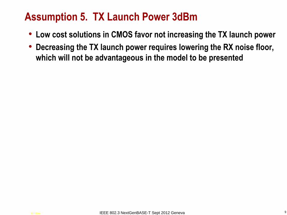
Assumption 5. TX Launch Power 3dBm
• Low cost solutions in CMOS favor not increasing the TX launch power
• Decreasing the TX launch power requires lowering the RX noise floor,
which will not be advantageous in the model to be presented
Will Bliss IEEE 802.3 NextGenBASE-T Sept 2012 Geneva

10
Assumption 6. Spectrum Band-limited to BW
• Where BW will be a design variable
• Assumption simplifies the model and discussion
• Low power constrained PHYs tend to soft band limit, because it’s too
expensive to either ‘over-sample’ or to implement accurate analog
continuous time ‘matched filters’
• Real performance tends to approximate the ideal band-limited
performance
Will Bliss IEEE 802.3 NextGenBASE-T Sept 2012 Geneva

11
Assumption 7. Operation only at medium to high SNR(f)
• Where SNR(f) is approximately equal to 1 + SNR(f)
• E.g., where 10*log10 SNR(f)) >= 6dB for all f
• Because it generally costs too much power to operate where a
significant fraction of the band is at low SNR(f)
Will Bliss IEEE 802.3 NextGenBASE-T Sept 2012 Geneva

12
Assumption 8. All noises are PHY self-noises
• All PHY noises and distortions (TX and RX) are lumped into a single
Bandwidth limited AWGN referred to the RX input
Will Bliss IEEE 802.3 NextGenBASE-T Sept 2012 Geneva

13
Band-Limited Shannon Capacity review
• For simplicity use flat (white) TX power spectrum
– No advantage to ‘Water filling’ spectrum for our medium to high SNR(f)
– See reference [A. Entshari, M. Kavehrda , “Transmission strategies for High-
Speed Access over Category-7A Copper Wiring,” CCECE’08, pp.1065-1068]
• So S(f) is simply the IL scaled by the TX launch power, and
• N(f) is simply the band-limited white self noise
Will Bliss IEEE 802.3 NextGenBASE-T Sept 2012 Geneva

14
10GBASE-T Baseline Reference Implementation
• Consider the ‘Channel’ (defined as what the communication engineer
can NOT change) of 100m of CAT6A with Power Sum Alien Xtalks
– The 400 MHz band-limited Shannon Capacity is 3.45Gbps / TP
– So 4 Twisted Pairs gives 4*3.45 = 13.8 Gbps, an apparent 38% ‘margin’
– But this apparent ‘capacity margin’ must cover the non-ideal modulation and
coding, as well as all other impairments.
– The actual modulation and code require 23.5dB detector SNR to achieve the
BER goal of 1e-12. This is 4.7dB from the Shannon bound without any
‘implementation penalty’, so there is much less margin than apparent above
• What would a PHY designer do with this Alien Xtalk dominated
system?
– Answer = ‘Hide’ all electronic implementation noises under the Alien Xtalk
• E.g., allow a 1.25dB degradation in net detector SNR compared to the Alien Xtalk
with perfect electronics
• Diminishing returns (and higher power ) from lowering ‘self-noises’ further
– Model the net of all 10GBASE-T self-noises as AWGN @ -143dBm/Hz
Will Bliss IEEE 802.3 NextGenBASE-T Sept 2012 Geneva

15
10GBASE-T, Hiding net Self Noise below PS Alien Xtalk
0 50 100 150 200 250 300 350 400-160
-150
-140
-130
-120
-110
-100
-90
-8010GBASE-T 100m. Launch=3dBm. Power Spectral Densities referred to RX Input
Frequency (MHz)
dB
m/H
z
Received Signal
PS Alien Xtalk
PS Self Noises Typical
Net Noises
• In order to ‘hide’
below the Alien Xtalk
(reduce the detector
SNR by 1.25dB), a
white input referred
‘self noise’ is placed
at -143 dBm/Hz
• This level of ‘self
noise’ at this band-
width will be our
‘unit reference’ for
relative power
comparisons
Will Bliss IEEE 802.3 NextGenBASE-T Sept 2012 Geneva
16
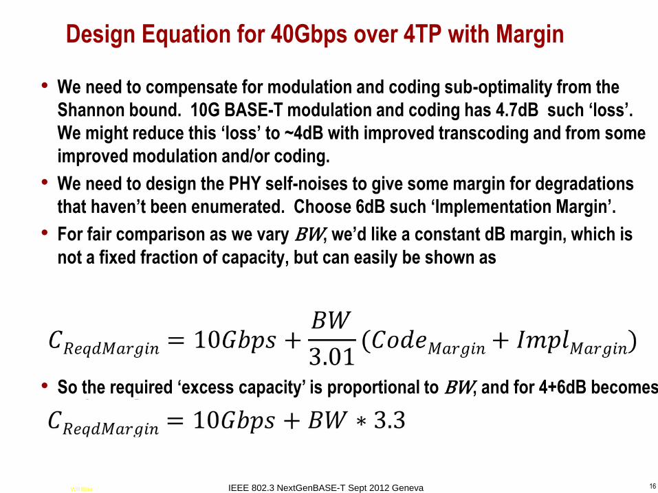
Design Equation for 40Gbps over 4TP with Margin
• We need to compensate for modulation and coding sub-optimality from the
Shannon bound. 10G BASE-T modulation and coding has 4.7dB such ‘loss’.
We might reduce this ‘loss’ to ~4dB with improved transcoding and from some
improved modulation and/or coding.
• We need to design the PHY self-noises to give some margin for degradations
that haven’t been enumerated. Choose 6dB such ‘Implementation Margin’.
• For fair comparison as we vary BW, we’d like a constant dB margin, which is
not a fixed fraction of capacity, but can easily be shown as
• So the required ‘excess capacity’ is proportional to BW, and for 4+6dB becomes
Will Bliss IEEE 802.3 NextGenBASE-T Sept 2012 Geneva

17
A Simple model of Relative Power
• Power is proportional to BW – Analog currents are typically proportional to BW, while voltages remain constant
– Number of digital computations (if they parallelize well) are typically proportional to
BW
• Power to achieve noise Power Spectral Density No doubles with every
6dB reduction of noise
– Analog currents must typically be doubled to reduce noise and distortion by 6dB,
while voltages remain constant
– E.g., increasing ADC Effective Number of Bits by +1bit (6db) doubles the power
– DSP costs probably don’t scale in this manner, as ‘one extra LSB’ of significance
lowers the DSP noises by 6dB. Thus, this model typically overstates the DSP power
at high SNRs (at low Baud rates)
– Denoting No in dBm/Hz units, then
• Equivalent to reference [G. Zimmerman, “Channel Parameters and PHY Complexity at 40G”,
TIA TR-42.7-2011-10-085]
Power ∝ BW * 2 -No/6.02
Will Bliss IEEE 802.3 NextGenBASE-T Sept 2012 Geneva

18
Relative Power vs. Reach at optimum BW. 40Gbps
0 10 20 30 40 50 60 70 80 90 10010
-1
100
101
102
reach (m)
Pow
er
Multip
lier
Power Multiplier wrt 10GB-T vs. Reach for 40Gbps. TXlaunch=3dBm, TotalMargin=10dB, Self Noise Only
• Every ~12m increase
in reach
approximately
doubles power
• About 4x Power/port
@ 46m (same pJ/bit
as 10GBASE-T)
• About 2x Power/port
@ 34m
• About 1x Power/port
@ 22m
Will Bliss IEEE 802.3 NextGenBASE-T Sept 2012 Geneva

19
Noise PSD vs. Reach at optimum BW. 40Gbps
0 10 20 30 40 50 60 70 80 90 100-180
-170
-160
-150
-140
-130
-120
-110
reach (m)
dB
m/H
z
White Noise PSD vs Reach at optimal BW for min Power. 40Gbps. TXlaunch=3dBm, TotalMargin=10dB, Self Noise Only
• Same -143dBm/Hz as
10GBASE-T @41m
• Below -150dBm/Hz
(above 54m) likely
requires radical new
circuit techniques
• And quickly reach
thermal noise limits
for 100 Ohms and
room temperature (or
worse, IC
temperature)
• Not reasonable
beyond 70m
Will Bliss IEEE 802.3 NextGenBASE-T Sept 2012 Geneva

20
BW vs. Reach at optimum BW. 40Gbps
0 10 20 30 40 50 60 70 80 90 100800
1000
1200
1400
1600
1800
2000
reach (m)
BW
MH
z
Bandwidth vs Reach that Minimizes Power. 40Gbps. TXlaunch=3dBm, TotalMargin=10dB, Self Noise Only
• Shorter reaches are
optimized with higher
BWs
• All reasonable
lengths are optimized
with BW > 1GHz
• So an ‘extrapolation’
of IL specification
seems needed?
Will Bliss IEEE 802.3 NextGenBASE-T Sept 2012 Geneva

21
Bits per second per Hz vs. BW. 40Gbps
400 600 800 1000 1200 1400 1600 1800 20005
10
15
20
25bits per second per Hz BW per TP for 40Gbps
BW MHz
bps/H
z
40Gbps
10G BASE-T
• For a given net data
rate, simple
hyperbolic
relationship between
BW and bits per
second per Hz of BW
Will Bliss IEEE 802.3 NextGenBASE-T Sept 2012 Geneva

22
Bits per second per Hz vs. Reach at Optimum BW. 40Gbps
0 10 20 30 40 50 60 70 80 90 1005
6
7
8
9
10
11
12
reach (m)
bps/H
z
bits per second per Hz BW vs Reach that Minimizes Power. 40Gbps. TXlaunch=3dBm, TotalMargin=10dB, Self Noise Only
• Only short reaches
<20m don’t require an
increase in bps/Hz
compared to
10GBASE-T
Will Bliss IEEE 802.3 NextGenBASE-T Sept 2012 Geneva

23
Relative Power vs. BW for 35m example. 40Gbps
400 600 800 1000 1200 1400 1600 1800 200010
0
101
102
Power vs. BW for 40Gbps. length=35m
BW MHz
rela
tive p
ow
er
• Example of reach =
35m
• The power minima is
quite broad for 35m
• And we expect the
model overly favors
high BWs
• How sub-optimal
would BW = 1GHz be
for other reaches?
Will Bliss IEEE 802.3 NextGenBASE-T Sept 2012 Geneva
24
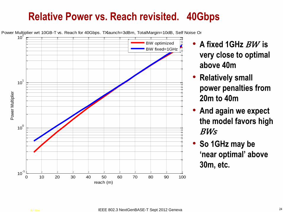
Relative Power vs. Reach revisited. 40Gbps
0 10 20 30 40 50 60 70 80 90 10010
-1
100
101
102
reach (m)
Pow
er
Multip
lier
Power Multiplier wrt 10GB-T vs. Reach for 40Gbps. TXlaunch=3dBm, TotalMargin=10dB, Self Noise Only
BW optimized
BW fixed=1GHz• A fixed 1GHz BW is
very close to optimal
above 40m
• Relatively small
power penalties from
20m to 40m
• And again we expect
the model favors high
BWs
• So 1GHz may be
‘near optimal’ above
30m, etc.
Will Bliss IEEE 802.3 NextGenBASE-T Sept 2012 Geneva

25
Summary of Results given the assumptions and model
• A very simple model of PHY power was given and referenced to a
baseline 10GBASE-T implementation
– The model is ‘analog centric’ and agnostic on modulation and coding methods
– The model deliberately underestimates Power by ignoring the more difficult RL at
higher BW
• Power approximately doubles for every 12m increase in reach
– Choice of the maximum supported reach will be a critical parameter
– Some technically viable long reaches may have too high power for ‘broad market
acceptance’
• >70m reach is not reasonable power nor technically feasible
• The same PHY power/port as 10GBASE-T is achieved at reach 22m
• The same PHY energy/bit as 10GBASE-T is achieved at reach 46m
• The Bandwidth that minimizes power is > 1GHz for reach < 70m, but
• Bandwidth of 1GHz is quite close to optimal for reach >30m
Will Bliss IEEE 802.3 NextGenBASE-T Sept 2012 Geneva

26
Discussion and Future Work
• No attempt here to predict advances in Silicon IC processes or design methods
– IC power is a moving target over time
– ‘Slope’ of Power vs. Reach will remain similar, but these curves can and will
‘shift.’
– E.g., an extra 6dB of dynamic range would cost 2x in power (12m reach)
• Better modeling of RL to higher BW is needed, including cables, magnetics,
and connectors
– The phase response is also needed to predict dynamic range requirements
• Better modeling of IL to higher BW is needed, including cables, magnetics, and
connectors
– The phase response is also needed
• Better and more detailed modeling of IC architecture is needed to refine results
– Modeling of DSP ‘digital centric’ power is needed to refine results
• Understanding EMI requirements is essential to a quick project start and to a
successful conclusion
– Shielding of Cables and/or Connectors may be preferred or needed
Will Bliss IEEE 802.3 NextGenBASE-T Sept 2012 Geneva