a setup for multi-uav hardware-in-the-loop simulations · a setup for multi-uav...
TRANSCRIPT
A Setup for Multi-UAV Hardware-in-the-LoopSimulations
Marcin Odelga, Paolo Stegagno, Heinrich H. Bülthoff and Aamir Ahmad
Abstract— In this paper, we present a hardware-in-the-loop simulation setup for multi-UAV systems. Withour setup we are able to command the robots simulatedin Gazebo, a popular open source ROS-enabled physicalsimulator, using computational units that are embeddedon our quadrotor UAVs. Hence, we can test in simulationnot only the correct execution of algorithms, but alsothe computational feasibility directly on the robot’shardware. In addition, since our setup is inherentlymulti-robot, we can also test the communication flowamong the robots. We provide two use cases to showthe characteristics of our setup.
I. INTRODUCTION
Latest trends in research on Unmanned AerialVehicles (UAVs) push for on-board integration ofhighly informative sensors such as laser scanners[1], cameras [2] and RGB-D devices [3], [4]. Theincrease in available information and the need toprocess it on-board requires also more compu-tational power directly embedded on the robots.However, due to payload and power consumptionconstraints, the on-board available computationalpower is not yet comparable to the one of a normaldesktop PC.
Another increasing trend is the use of physicalsimulations to test algorithms for robotics beforethe real hardware implementation phase. They areparticularly useful when considering UAVs, sinceeach experiment can be time consuming and couldeven result in a crash. However, whenever portingan algorithm from simulation to the real hardware,temporization issues may arise due to the limitedon-board computational power. The main problem
All authors are with the Max Planck Institute forBiological Cybernetics, Department of Human PerceptionCognition and Action, Spemannstrasse 38, 72076Tübingen, Germany {pstegagno, modelga, hhb,aamir.ahmad}@tuebingen.mpg.de
is that simulations usually run on a different hard-ware than the one equipped on-board, hence notallowing to check the real execution time of thesoftware.
Hardware-in-the-loop (HIL) simulation [5] is agood way to test these aspects without a need ofreal robot experiments. In [6] the authors presenta UAV system with HIL simulation for testing theplatform with real-time data and real environment.Their system constitutes of a reliable platform fortesting critical safety properties with special atten-tion. Thus, through HIL simulation they greatlyreduce experimental costs. Another HIL setup, fora UAV helicopter, can be seen in [7]. The authorsshow its cost-efficiency in terms of verification ofthe overall control performance and safety. Theirsystem, capable of simulating flight tests including,e.g., basic flight motions and full-envelope flights,confirms the high effectiveness and usefulness ofHIL simulations.
In this paper, we present our setup for HIL sim-ulations which consist of two main parts. The firstis Gazebo, a popular open source ROS-enabledsimulator, which provides the dynamical simula-tion of one ore more UAVs and the correspondingsensor readings (IMU, cameras, etc.). On the otherhand, each of the simulated UAVs is driven usingan ARM-based Odroid board, which is the highlevel control board installed on our quadrotors. Theinterfacing between the components is provided bya ROS (Robot Operating System) node based onthe Telekyb software ([8]).
Using this simulation scheme, we obtain twomajor benefits with respect to a normal simulation.First, we can test algorithms directly on the on-board computational units, hence also testing thecomputational times and the feasibility in real-time. In addition, since our setup is meant for

multi-robot systems, we can also test the commu-nication among multiple boards.
The rest of the paper is as follows. In Sect. IIwe describe our hardware platform. In Sect. IIIwe explain in detail the software setup to performhardware-in-the-loop simulations. In Sect. IV weshow two case studies in which we demonstratethe feasibility of hardware-in-the-loop simulationsin both single and multi-UAV systems, and Sect.V concludes the paper.
II. UAV PLATFORM
Our robotic setup is made of multiple UAVs:MK-Quadro quadrotors from MikroKopter. EachUAV consists of a frame with four 10 inch pro-pellers powered by brushless motors, motor con-trollers and a flight controller board with an 8-bitmicrocontroller. The main board includes an in-ertial measurement unit (IMU), i.e., two 3-axis,10-bit analog sensors: an accelerometer (witha range of ±2 g) and a gyroscope (±300 deg/srange), both read with an analog to digital con-verter. The board communicates with the brushlessmotor controllers through a standard I2C bus andoffers two serial connections with a 115 200 Bdbaud rate.
The original firmware, which allows us to drivethe quadcopter with a remote control, has beenreplaced with our own software that has newfeatures and a different interface that allows usto control the robot through serial channels. Thefirst channel is used to send attitude and thrustcommands to the microcontroller at ~100 Hz, andto receive low-frequency data (~20 Hz) (i.e. batterylevel). The second channel, strictly unidirectional,is used to retrieve high frequency IMU readings at500 Hz. The platform is powered by a 2600 mAhLiPo battery that provides approximately 10 minof flight.
In addition, we have equipped the system withOdroid-XU3, a double quad core1 ARM micropro-cessor board that provides enough computationalpower to make the system independent of externalcomputational units. High computational power toweight/size ratio and low cost make this board
1four Cortex-A15 at 2.0 Ghz, four Cortex-A7 and HeterogeneousMulti-Processing (HMP) solution for tasks management
Fig. 1: One of our UAVs.
relatively popular among the robotics community.It enables the use of high computationally de-manding algorithms, e.g., visual based odometryand mapping ([4], [2], [9]) or advanced controlmethods such as model predictive control ([10]),directly on the platform.
Communication with the low-level flight con-troller is carried out by two serial adapters con-nected to XU3’s USB ports. Power to the boardand its peripherals is provided by a 5 V step-downvoltage regulator connected to the LiPo battery.The board can exchange data with the fixed opera-tor desk using a USB Wi-Fi adapter. The completeplatform is depicted in Fig. 1.
III. SOFTWARE SETUP
In this section, we describe first the softwaresetup to drive a single UAV. Then, we show oppor-tune modifications in order to run HIL simulations.Finally, we point out the required steps to performmulti-robot HIL simulations.
A. UAV control
In order to control a quadrotor, we use a soft-ware setup as depicted in Fig. 2. Being installedwith the Ubuntu 14.04 ARM distribution, theOdroid board is ROS enabled, hence we can runthe Telekyb software and its high-level controllerand algorithms. Moreover, we can exploit ROScommunication topics to connect it to a basestation equipped with input/feedback devices. Inaddition, the base station may host appropriate rou-tines to read measurements provided by a motioncapture system (Vicon), if present, and translatethem into ROS topics.

ScreenVicon
JoystickHaptic interface
hardwareinterface low-level
control
Telekyb(high-level
control and algorithms)
Odroid
serial connection
Quadrotor
thrust, attitude,yaw rate
commands
IMU data
ROStopics
on-board sensors
sensor interface
ROS topics
USB serial
commands
IMU data
basestation
ROS topics overwireless IEEE 802.11
connection
feedback forthe operator
pose,inputs fromthe operator
Fig. 2: A block scheme of our UAV setup.
Similarly, Telekyb modules are interfacedthrough ROS topics with a ROS node to connectit with the hardware. The role of this block is toencrypt and send the commands (desired thrust, at-titude and yaw rate) to the microcontroller throughthe serial connection. The low-level controller isthen in charge of driving the propellers’ motorsto follow the received commands. Similarly, theblock receives IMU and battery status data fromthe microcontroller and translates them on ROStopics.
The UAV can be equipped with additional sen-sors such as cameras, RGB-D sensors, laser scan-ners, and GPS modules. In general, they can beconnected through serial and USB ports which arepresent on the Odroid board. The interfacing withthe high-level controller and algorithms is obtainedonce again with specific ROS nodes that translatesthe measurements into ROS topics.
B. Hardware-in-the-loop
In order to perform HIL simulations, we canexploit the standardization of the input/output pro-vided by Telekyb, whose interfacing with otherblocks is run solely through ROS topics. A blockscheme of our setup to perform hardware-in-the-loop simulations is depicted in Fig. 3. With respectto the scheme in Fig. 2, the hardware and sensorinterface block has been replaced with a Gazebointerface block. Its main functionality is to providean interfacing layer between Gazebo and the high-level control and algorithms.
In particular, it uses data provided by the sensorsand ground truth in Gazebo to emulate the ROStopics provided by the Vicon tracking system (if
required), IMU, cameras and other sensors presentboth in the simulation and the real robot setup. Theemulation not only comprises the specific topicsand format on which the data are provided byGazebo, but also take care of the temporization.For example, our real Vicon system provides dataat 120Hz, while the physical simulation is per-formed with a timestep of 1ms, so that groundtruth pose information about the UAV is availableat 1000Hz. Nevertheless, the pose provided to theTelekyb blocks is temporized at 120Hz by theGazebo interface.
On the other hand, the Gazebo interface trans-lates the thrust, attitude and yaw rate commandsprovided by the high-level controller into com-mands that can be read from the simulator andapplied to the simulated UAV model.
The interfacing with the base station and theoperator does not change with respect to the realrobot system. The Gazebo simulator can be hostedeither on the base station or on another machine.In order to test also the communication link be-tween the robot and the base station, the latteris preferred, while the first can be implementedif the objective of the simulation is only to testthe functionality and the execution time of theimplemented algorithms. In both cases, the com-munication between the Odroid board and Gazebois achieved through ROS topics over IEEE 802.11connection.
C. Multi-robot
Since all components of the hardware-in-the-loop simulation, and in particular Telekyb, are in-herently thought for multi-robot applications, only

ROS topics overIEEE 802.11connection
thrust, attitude,yaw rate
commands
IMU data, pose,on-board sensors
Odroid
ROS topics
simulated on-boardsensor measurements
basestation
ScreenJoystick
Haptic interface
ROS topics overwireless IEEE 802.11
connection
feedback forthe operator
inputs fromthe operator
Host PCwith
Gazebo
Gazebointerface
Telekyb(high-level
control and algorithms)
ROStopics
commands
IMU datapose
Fig. 3: A block scheme of the hardware-in-the-loop simulation setup.
Odroid 1
base stationhuman
interfaces
Host PC with Gazebo
Gazebointerface_1
Telekyb_1
Odroid 2Gazebo
interface_2
Telekyb_2 Odroid nGazebo
interface_n
Telekyb_n
. . .
inter-robotcommunication
network
Fig. 4: A block scheme of the multi-robothardware-in-the-loop simulation setup.
few adjustments are required to perform multi-robot HIL simulations.
The most important thing is that each robotsimulated in Gazebo is endowed with a uniqueidentifier ID, which must be inserted in the nameof all ROS nodes and topics relative to such robot.Hence, for each robot in Gazebo, one Odroid boardis setup to host a Gazebo interface that reads theappropriate topics (i.e.: the topics containing theown ID) and a Telekyb instance connected to suchID. Each Odroid is also connected to the basestation in the same way as the previous case. Theresulting scheme is presented in Fig. 4.
In addition to the single robot case, it is alsopossible to test the inter-robot communication net-work. At the current stage of development, thecommunication between robots is yet again per-formed exploiting ROS topics on a wireless IEEE802.11 channel. Nevertheless, it is also possible to
include and test custom communication networksamong the robots equipping Odroid boards withappropriate hardware (e.g.: bluetooth antennas).
IV. CASE STUDY
As examples of the functionalities of ourhardware-in-the-loop setup, we present in thissection two case studies. In the first case study,we will show a single robot obstacle avoidancesimulation and the corresponding experiment witha real robot. The aim is to show the same behaviorin these two systems, which proves the possibilityto test complex algorithms in simulation.
In the second case study, we highlight the multi-robot capabilities of our hardware-in-the-loop sim-ulation scheme by performing formation controlwith three simulated UAVs driven by three Odroidboards.
A. Obstacle Avoidance
In this case study, we show an obstacle avoid-ance experiment performed both in simulation andon a real robot. The algorithm is divided into twomain modules. The first module maps the obstaclesin the proximity of the robot detected using depthimages from an on-board RGB-D sensor. The sec-ond module, the avoidance part, works on a sharedcontrol principle as the user input, the velocitycommanded by the operator, is altered to preventcollisions. The algorithm can override commandsby adding a lateral and/or vertical component. Theresulting reference velocity is then provided to thevelocity controller of the robot2. To facilitate the
2Further details of this method are not in the scope of this paper.A manuscript explaining this algorithm in detail is in the reviewprocess during the preparation of this paper.

Fig. 5: Three comparative snapshots of the same obstacle avoidance algorithm performed in hardware-in-the-loop simulation (top) and a real UAV experiment (bottom).
-1-0.5
yW
00
0.5
1
1.5
2
xW
2.5
3
1
0.5
0
3.5
zW
UAV trajectory
commanded velocity
avoidance velocity
obstacle
-1-0.5
yW
00
0.5
1
1.5
2
xW
2.5
3
0
0.5
1
3.5
zW
UAV trajectory
commanded velocity
avoidance velocity
obstacle
Fig. 6: The comparison of trajectories performed by the UAV in a real experiment (left) and in hardware-in-the-loop simulations (right).
teleoperation task the operator is provided with avisual and haptic feedback.
The on-board RGB-D sensor (Asus Xtion Pro),used as the source of data for obstacle detection,is mounted approximately 45° to the right withrespect to the front propeller and rotated 90°around the camera axis to extend the vertical fieldof view (FOV). It is also rotated downward atabout 20° to increase the number of visual featuresinside the FOV by framing a bigger portion of theground, while simultaneously offering a horizontalline of sight to the operator. The Odroid boardand the camera are attached rigidly to the framewith 3D printed parts. The UAV used in the realexperiment and equipped with the RGB-D sensorweights approximately 1.3 kg.
In order to conduct the experiment with sim-ulated UAV and sensor readings the same setupis recreated in Gazebo using a dynamic model ofmultirotor3. Color and depth images are generatedthanks to an RGB-D sensor plug-in. The intrinsicand extrinsic parameters, i.e. camera parametersand sensor pose, respectively, are set to match thereal hardware.
We have conducted experiments of lateral avoid-ance of a vertical obstacle, both in simulation andusing the real robot. The human operator wascommanding the robot to go towards the edgeof the obstacle. In Fig. 5 snapshots from theexperiments are presented and show consecutivepositions of the robot during the flight. Full trajec-tories, together with the commanded and referencevelocities, are presented in Fig. 6. Both Figuresshow that the real and the simulated robot havethe same behavior in the experiment.
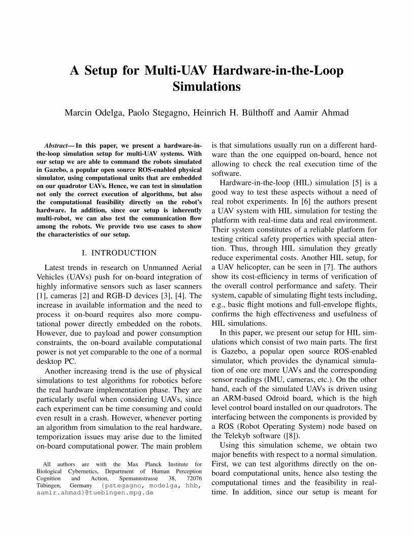
In Table I we show mean values (µ) and standarddeviations (σ) of the execution time of two mod-ules of the algorithm. These modules are relatedto the data processing of depth images and robot’sstate estimate, respectively. We have run the sameexperiment on three different platforms: standarddesktop PC, hardware-in-the-loop simulation, andthe real platform. Table I shows that the computa-tional times obtained in the PC simulation is verydifferent with respect to the timing obtained in the
3https://github.com/ethz-asl/rotors_simulator
Module 1 Module 2µ [ms] σ [ms] µ [ms] σ [ms]
PC <1 - <1 -HIL 1.74 0.302 5.3 1.42
Robot 1.95 0.339 5.65 0.78
TABLE I: Execution Time Comparison
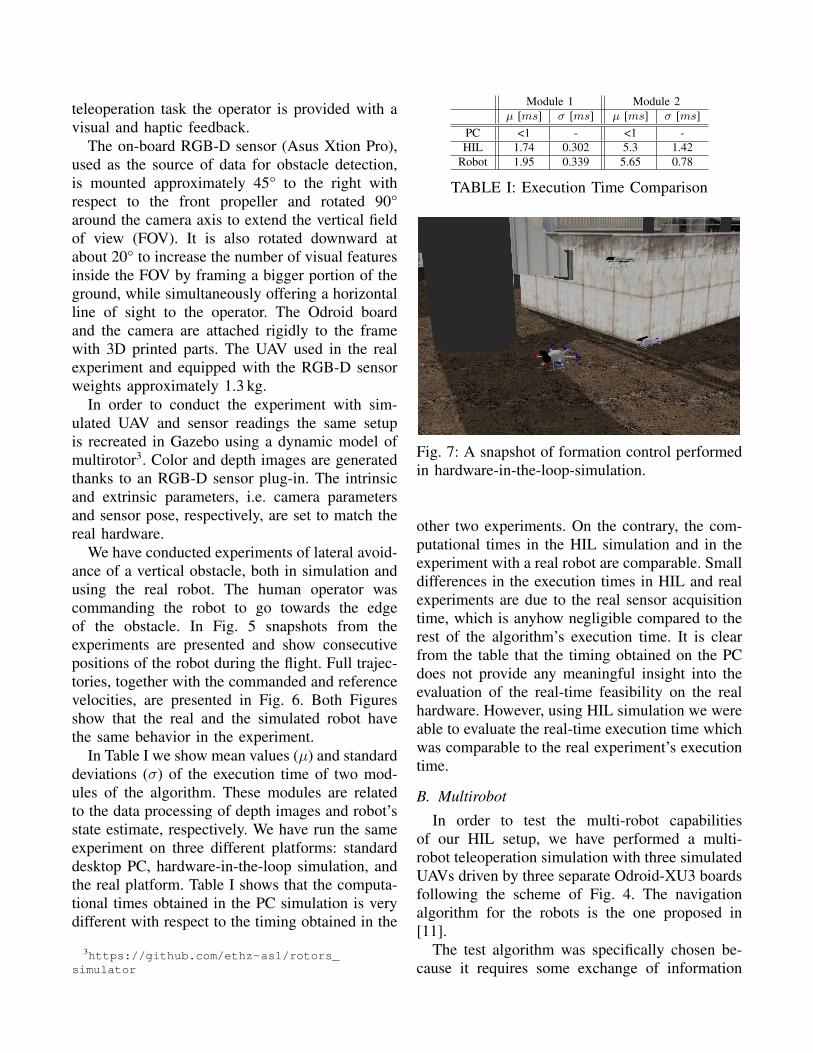
Fig. 7: A snapshot of formation control performedin hardware-in-the-loop-simulation.
other two experiments. On the contrary, the com-putational times in the HIL simulation and in theexperiment with a real robot are comparable. Smalldifferences in the execution times in HIL and realexperiments are due to the real sensor acquisitiontime, which is anyhow negligible compared to therest of the algorithm’s execution time. It is clearfrom the table that the timing obtained on the PCdoes not provide any meaningful insight into theevaluation of the real-time feasibility on the realhardware. However, using HIL simulation we wereable to evaluate the real-time execution time whichwas comparable to the real experiment’s executiontime.
B. Multirobot
In order to test the multi-robot capabilitiesof our HIL setup, we have performed a multi-robot teleoperation simulation with three simulatedUAVs driven by three separate Odroid-XU3 boardsfollowing the scheme of Fig. 4. The navigationalgorithm for the robots is the one proposed in[11].
The test algorithm was specifically chosen be-cause it requires some exchange of information

among the robots in order to achieve consensus onthe status of the system. This inter-robot commu-nication was performed using the wireless IEEE802.11 capabilities of the Odroid-XU3 boards.In Fig. 7 we show one snapshot of this simu-lation. The interested reader is invited to watchthe video clip of this and the previous simulationand experiments in the accompanying multimediaattachment.
V. CONCLUSIONIn this paper, we have presented a UAV
hardware-in-the-loop simulation scheme which al-lows us to test the computational requirementsof our algorithms directly on the computationalunit that is equipped on the robots, while si-multaneously enjoying the safety of a simulation.Additionally, we can perform multi-robot HILsimulations to test the communication among therobots.
The use of HIL simulations was very usefulduring the development of an obstacle avoidancealgorithm, especially in terms of time needed toperform experiments. In fact, it was possible totest various parameters without the need to runreal experiments. The use of the actual hardware(Odroid-XU3) in the simulations allowed to checkif the execution times of the various modules werecompatible with the on-line execution.
As future development, we plan to extend thesystem to include other types of robots (e.g.:wheeled robots) and test other types of commu-nication networks (e.g.: bluetooth).
REFERENCES
[1] S. Omari, M.-D. Hua, G. Ducard, and T. Hamel, “BilateralHaptic Teleoperation of an Industrial Multirotor UAV,” inGearing up and accelerating cross-fertilization between aca-demic and industrial robotics research in Europe, SpringerInternational Publishing, 2014, pp. 301-320.
[2] C. Forster, M. Pizzoli, and D. Scaramuzza, “SVO: Fast Semi-Direct Monocular Visual Odometry,” in IEEE InternationalConference on Robotics and Automation (ICRA), 2014.
[3] P. Stegagno, M. Basile, H. H. Büthoff, and A. Franchi, “ASemi-autonomous UAV Platform for Indoor Remote Opera-tion with Visual and Haptic Feedback,” in IEEE InternationalConference on Robotics and Automation (ICRA), 2014, pp.3862-3869.
[4] Z. Fang and S. Scherer, “Real-time Onboard 6DoF Local-ization of an Indoor MAV in Degraded Visual EnvironmentsUsing a RGB-D Camera,” in IEEE International Conferenceon Robotics and Automation (ICRA), May 2015.
[5] J. Burbank, W. Kasch, and J. Ward, “Hardware-in-the-LoopSimulations," in An Introduction to Network Modeling andSimulation for the Practicing Engineer, 1, Wiley-IEEE Press,2011, pp.114-142.
[6] V.K. Chandhrasekaran and Choi Eunmi, “Fault tolerancesystem for UAV using hardware in the Loop Simulation,” inInternational Conference on New Trends in Information Sci-ence and Service Science (NISS), 11-13 May 2010, pp.293-300.
[7] G. Cai, B. M. Chen, T. H. Lee, and M. Dong, “Design andimplementation of a hardware-in-the-loop simulation systemfor small-scale UAV helicopters,” in IEEE International Con-ference on Automation and Logistics (ICAL), 1-3 Sept. 2008,pp.29-34.
[8] V. Grabe, M. Riedel, H. H. Bülthoff, P. R. Giordano, andA. Franchi, “The TeleKyb framework for a modular andextendible ROS-based quadrotor control,” in European Con-ference on Mobile Robots (ECMR), 25-27 Sept. 2013., pp.19-25.
[9] G. Mohanarajah, V. Usenko, M. Singh, M. Waibel, and R.D’Andrea, “Cloud-based collaborative 3D mapping in real-time with low-cost robots,” in IEEE Transactions on Automa-tion Science and Engineering, March 2014.
[10] Y. Liu, J. M. Montenbruck, P. Stegagno, F. Allgöwer, A.Zell, “A Robust Nonlinear Controller for Nontrivial QuadrotorManeuvers: Approach and Verification”, in IEEE/RSJ Interna-tional Conference on Intelligent Robots and Systems (IROS),28th Sep-3rd Oct 2015.
[11] A. Franchi, C. Secchi, H. I. Son, H. H. Bülthoff and P.Robuffo Giordano, “Bilateral Teleoperation of Groups ofMobile Robots with Time-Varying Topology” in IEEE Trans-action on Robotics, 28(5) pp. 1019-1033, Oct 2012.