a sensorless closing control for an ac contactor based on ... · a sensorless closing control for...
TRANSCRIPT
A Sensorless Closing Control for an AC Contactor Based on a NewArmature Displacement Estimator
CHIEH-TSUNG CHIDepartment of Electrical Engineering
Chienkuo Technology UniversityNo. 1, Chieh Shou N. Rd., Changhua City 500, Taiwan, R.O.C
E-mail: [email protected]
Abstract: - This paper presents a new approach to solve the contact bounce after contacts closingproblem for prolonging the lifespan and improving operation reliability. Based on combining aarmature displacement estimator (ADE) with a simple hysteresis controller, such that the coil-currentdifference between the ac electromagnetic contactor (abbreviated ac contactor) body and the estimatoris minimized, the proposed method overcomes the installation of an armature displacement measuringmechanism is indispensable restrictions imposed by previously described closing controlmethodologies. By using the proposed algorithm, an efficient control configuration can be obtained toreduce bounce duration. Computer simulations, of the proposed method, illustrate lots of benefits thatare provided by proposed sensorless closing control configuration.
Key-Words: - Contact bounce, Estimator, Hysteresis controller, Armature displacement, Sensorless,AC electromagnetic contactor.
1 IntroductionCurrently, a large number of contactors havewidely used in industrial switchgear equipments[1-3]. Most of them are applied in the powertransmission and control systems formaking/opening the power source of load. Whencontactor is applied to a voltage source, the inputelectrical energy is converted into the mechanicalenergy for doing work to armature. In many cases,since the armature of contactor with too muchkinetic energy at the contacts closing instant, thisresult leads to an inelastic collision betweencontacts. Consequently, resulting in an uncertainnumber of rebounds after the first touch could beproduced before they reach a permanent state ofcontact. If the contactor is specified to work in theAC3 category, the starting current of loadgenerally is about 6-10 times of the rated loadcurrent, such as the starting current of inductionmotor and the switching an uncharged capacitor inparallel with a charged capacitor bank [4].Supposed that contactor is utilized in three phasesystem, as result of the contact bounces andstarting current occurs at the same time, arcingwith high temperature must be harmful to thecontacts of contactor.
The contact bounces with erosion have beenthoroughly investigated in the past [4-6]. Manyauthors have discussed the contact bouncingproblems related to the reduction of bounceduration after contacts closing by using numerousmethodologies [7,13-18]. For example, Nouri et al.first reported the production of contact bounce thatis caused by the excessive kinetic energy prior totwo contacts impact. Therefore, Nouri et al.proposed a new approach for the reduction of thekinetic energy of armature. According to thearmature displacement, they effectively controlledthe kinetic energy of armature by using the powerelectronic technology [8]. In addition, Li et al.made use of experimental method; they found thatif user purposely selects the closing phase angle ofac voltage source to energize the ac contactor, aminimized kinetic energy was derived [9]. Later,related to searching an optimal closing phase anglehas been taken as optimization problem by Su et al.[10]. In a similar manner, Zhang [11] presentedthat if the ac contactor can be energized at themoment of the zero crossing point of load current,in theory, even if contact bounce occurs, there isno any energy dissipated between two contacts.Therefore, no influence on the lifespan of contactis obtained.
WSEAS TRANSACTIONS on INFORMATION SCIENCE and APPLICATIONS Chieh-Tsung Chi
ISSN: 1790-0832 1687 Issue 12, Volume 5, December 2008
Although many studies have been publishedconcerning the reduction of contact bounce, nomatter which they use open- or close-loop methodto control the closing process of ac contactor. Ingeneral, the dynamic armature-displacement datamust be provided to their system controller. Toachieve this goal, it is essential to arrange a propermeasuring sensor on the contactor mechanism.Several critical drawbacks are then produced, suchthat armature mass becomes heavier,manufacturing cost becomes inexpensive, and theusing durability is shortened. In recent years,Espinosa et al. [12] presented a close-loop methodto control the kinetic energy that acts on armatureduring closing process based on estimation method.
A new dynamic ADE is proposed in this paper.With application of both the coil voltage and thecoil current values, the dynamic armaturedisplacement can be estimated by proposedcalculation algorithm. Feasibility and robustnessof the proposed ADE are validated through severalexperimental and simulation tests. The developedADE was again combined with a hysteresiscontroller to implement the objective of contactbounce control during closing process. Themethods reported here could be beneficial toresearch attempting to increase the performance ofcontactors.
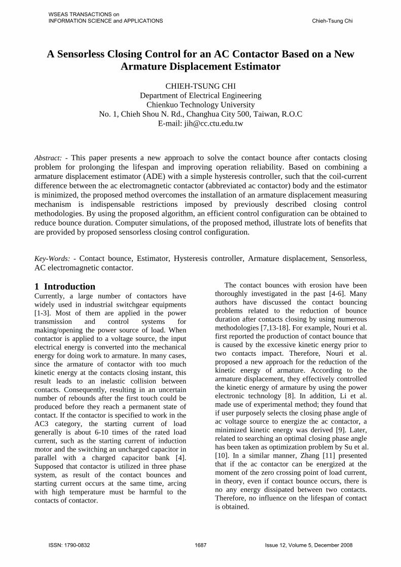
2 Structures and Energy ConversionFig. 1 shows the basic configuration of a typical accontactor. The ac contactor is generally seemed asan electromechanical system and composed ofthree parts, such as the electrical system, losslessmagnetic energy-conversion system andmechanical system. Included facilities of theelectrical system are the applied voltage source,current-carrying conductor and exciting coil. It isresponsible for providing the energy to themagnetic energy conversion system. Magneticenergy-conversion system is composed by themovable core, stationary core and air gapsbetween the cores. For this type of system themagnetic field serves as the coupling mediumbetween electrical system and mechanical system.On one hand, the input electrical energy isconverted into coupling field, and on the otherhand, part of energy is further transferred to themechanical system for moving the armature. Themechanical system consists of an armature, one ortriple sets of contacts, return springs and contacts’springs. It is responsible for managing thetransferred energy from the magnetic energy-conversion system and moving the armature if the
strength of magnetic force is larger than the springtension force.
Fig. 1. Shows the basic configuration of an accontactor.
Fig. 2. Lossless magnetic energy-conversionsystem is represented as two-port element.
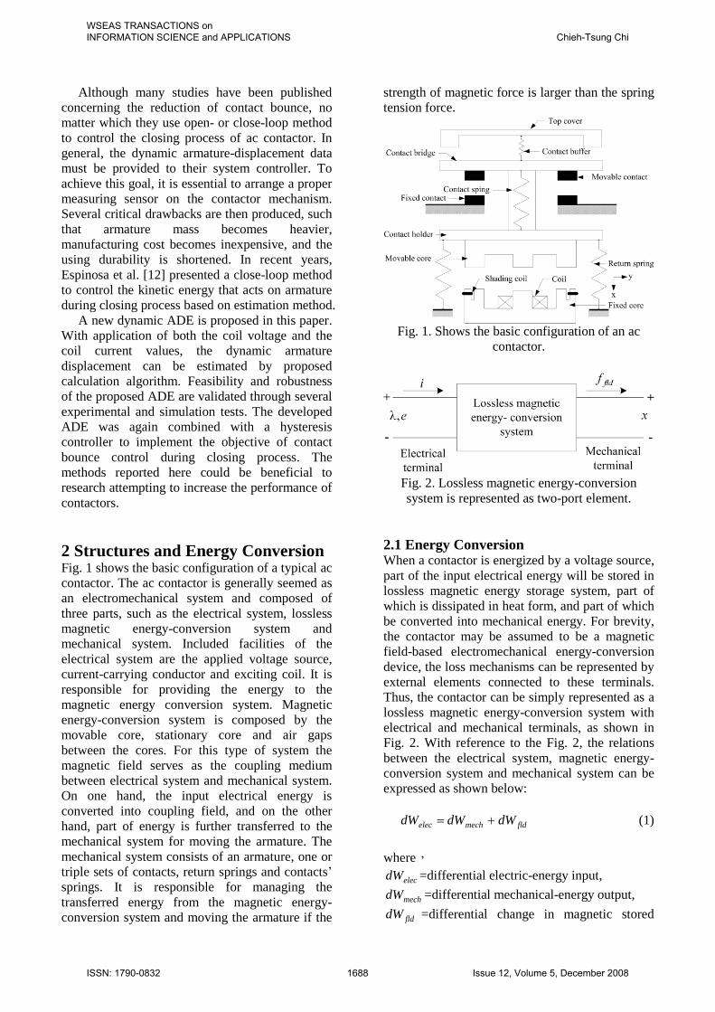
2.1 Energy ConversionWhen a contactor is energized by a voltage source,part of the input electrical energy will be stored inlossless magnetic energy storage system, part ofwhich is dissipated in heat form, and part of whichbe converted into mechanical energy. For brevity,the contactor may be assumed to be a magneticfield-based electromechanical energy-conversiondevice, the loss mechanisms can be represented byexternal elements connected to these terminals.Thus, the contactor can be simply represented as alossless magnetic energy-conversion system withelectrical and mechanical terminals, as shown inFig. 2. With reference to the Fig. 2, the relationsbetween the electrical system, magnetic energy-conversion system and mechanical system can beexpressed as shown below:
fldmechelec dWdWdW (1)
where,
elecdW =differential electric-energy input,
mechdW =differential mechanical-energy output,
flddW =differential change in magnetic stored
WSEAS TRANSACTIONS on INFORMATION SCIENCE and APPLICATIONS Chieh-Tsung Chi
ISSN: 1790-0832 1688 Issue 12, Volume 5, December 2008

energy.Indeed, the input electrical energy supplied
from the voltage source can be written as follows:
dtiedWelec (2)
By applying the Faraday’s law, the inducedvoltage across the coil e can be represented interms of the flux linkage as
dtd
e
(3)
For convenience, the magnetic energy-conversion system can be assumed to be a losslessand conservative. This means the energy stored incoupling fields is a function of the state of theelectrical and mechanical variables. In fact, tominimize the hysteresis and eddy losses, theferromagnetic material is purposely selected andarranged in laminations. Therefore, the flux flowsthrough the cores can be assumed the same as thatof the air gap. It varies proportionally with the coilcurrent. In other words, the flux linkage and thecoil current i are considered to be linearly relatedby a factor which depends solely upon thegeometry and hence the armature position x .
ixL )( (4)
Equation (4) points out the magnetic circuit canbe described by an inductance L which is afunction of the geometry of the magnetic structureand permeability of the magnetic material.
2.2 Electromagnetic ForceAssuming work done by the electromagnetic
force fldf is defined as energy transfer from
coupling fields to mechanical system mechdW , it isgiven by
dxfdW fldmech (5)
Substituting (3) and (5) into (1), we get
dxfiddW fldfld (6)
Since the magnetic energy-conversion system islossless and conservative, hence, the value of
fldW can be uniquely specified by the independent
variablesand x .Substitutes (4) into (6) and for a specified
armature displacement x , that is 0dx . Therepresentation of the coupling energy fldW can be
given by the following form:
)(2
)(2
0
xL
dxL
W fld
(7)
where is the dummy variable of integration.Since )(),( xLxi , the other form of (7) isexpressed as follows:
)(21 2 xLiW fld (8)
The fldW is a state function and determined
uniquely by the values of the independent statevariables and x .
dxx
Wd
WxdW fldfld
fld
),( (9)
Equation (9) is compared with (6) yields
x
xWf fld
fld
),((10)
The electromagnetic force fldf acts on armature
can be determined by using (10). Alternatively,one can use a state function other than energy,namely, the coenergy, to obtain the magnetic forcedirectly as a function of current.
),(),( xiWixiW fldfld (11)
Taking the derivative of the first term in the rightside of (11), yields
diidid )( (12)
Substitution of (6) and (12) into (11), results in
dxfdixiWd fldfld ),( (13)
WSEAS TRANSACTIONS on INFORMATION SCIENCE and APPLICATIONS Chieh-Tsung Chi
ISSN: 1790-0832 1689 Issue 12, Volume 5, December 2008

Coenergy, ),( xiW fld , means that is a function of
the two independent variables i and x . Thus, itsderivative with respect to these independentvariables is derived and presented as follows:
dxx
Wdi
i
WxiWd fldfld
fld
),( (14)
Equations (13) and (14) must be equal for all thecoefficients of di and dx ; thus
x
Wf fld
fld
(15)
Equation (15) means the electromagnetic forceacts on armature that can be further written by thederivative of coenergy representation as shownbelow:
dxxdL
i
x
Wf fld
fld
)(21 2
(16)
3 Closing Process AnalysisFig. 3 shows the typical configuration of anelectromagnetic contactor. The electrical system ismerely represented by a voltage source )(tu and afixed resistor r . Based on Kirchhoff’s voltage law,the voltage equation in electrical system may beexpressed as follows:
dtd
irtu
)( (17)
Since the flux linkage can be expressed as (4),it is substituted into (17) and results in
dtdx
dtxdL
idtdi
xLirtu)(
)()( (18)
The term dtdiL is the self-inductance voltageterm and the term ))(( dtdxdxdLi is the velocity-voltage term, which is responsible for the energytransfer between the external electrical system andlossless magnetic energy-conversion system.
In the mechanical system, m represents thearmature mass while the spring and damper arerepresented by a spring constant K and a dampingcoefficient D , respectively. The armature
displacement 0x is the equilibrium position of themechanical system where the armature is atopening position Similarly, the dynamic behaviorof the translational mechanical system can bedescribed by Newton’s motion law, so that
fldfxxKdtdx
Ddt
xdmf )( 02
2
(19)
Fig. 3. Sketches all the subsystems of a typical accontactor.
Fig. 4. Energy transfer of ac contactor in bothmotoring and generatoring modes.
To make use the principle of energy conservation,Fig. 4 shows that the lossless electromechanicalenergy-conversion system intervenes between theelectrical system and the mechanical system. Itserved as the coupling medium between these twosystems. Energy transferred direction of themechanical energy is determined by the movingdirection of the armature. If the mechanical energyis positive, it represents that the armature engagedwith the fixed core and the contactor fulfils themotor action; on the contrarily, if the mechanicalenergy is negative, it represents that the armaturedisengaged from the fixed core, and the contactorperforms the generator action. Moreover, there isanother important result can be deduced from (5)
k
v
v
x
x fldmech
Emvmv
dvmv
dxfW
20
2
21
21
0
0
(20)
WSEAS TRANSACTIONS on INFORMATION SCIENCE and APPLICATIONS Chieh-Tsung Chi
ISSN: 1790-0832 1690 Issue 12, Volume 5, December 2008
Equation (20) indicates the work done by theelectromagnetic force equals the change in thekinetic energy of the armature. Indeed, (20) iscommonly referred to as the work-energy theorem[19]. The symbol kE represents the differentialkinetic energy of the armature during theconsidered armature displacement period. In theFig. 3, 0x and 0v indicates the initial displacementand velocity of the armature, respectively; let xand v be the instantaneous armature displacementand moving velocity, and 0xx . In case of thearmature displacement and moving velocity at themoment of two contacts impact are taken as thefinal displacement and velocity in (20). It is moreclearly depicted that total amount of the kineticenergy or moving velocity with contacts prior toimpact may properly be controlled by means of theelectromagnetic force. In the closing process, thecoil current generally varies exponentially with thevalue of ac voltage source. For an AC contactor,the relationship between the coil current and theflux is linear and the representation can berepresented as follows:
)cos(2
0
wtSx
IN
rl (21)
Since the flux linkage NixLxi )(),( and coilinductance varies inversely proportional to thetotal reluctance value )(xR , thus, the magneticforce, which has represented as shown (16), couldbe derived in another form
S
dxxdR
f fld
0
2
2
2
)(21
(22)
where, the relevant symbols in (21) and(22) aredefined as follows:
)(xR : the reluctance in the magnetic circuit,
0 : the absolute permeability in the air, equal to
mH /104 7N : a number of windings in the coil,I : the rms current-carrying coil,
lx : the average length of the magnetic circuit,
r : the relative permeability of the coil substancesS : the cross-sectional area of the air gap,
: the instantaneous flux.Obviously, (22) shows the electromagnetic acts onthe armature during closing process is determined
by the square of the coil current or the fluxstrength in the magnetic circuit [11]. In a word, thekinetic energy with armature before contactsclosing actually can be achieved by controlling thevalue of applied coil voltage.
4 Sensorless Armature DisplacementEstimator (ADE)Based on the work-energy theorem, as can be seenin (20), the kinetic energy in armature duringclosing process can be effectively controlled bychanging the applied voltage source value. Fig. 5shows an overall close-loop block diagrams for anac contactor by using sensorless closing controlmethod. The resultant force betweenelectromagnetic force and spring anti-force
errorf and the armature displacement x are servedas the input variables of the hysteresis controller[20,21]. The upper and lower limit force error isautomatically determined by the armaturedisplacement. The output of the hysteresiscontroller is again integrated with a pulse widthmodulation generator to control the appliedvoltage source value. In addition to the kineticenergy in armature before contacts closing isconsidered, it is essential to shorten the totalclosing time as possible as. To attain above-mentioned goals, the closing process of accontactor is divided into three subdivisions, suchas acceleration region, deceleration region andholding region. The first stage is accelerationregion in which the ac contactor is applied by themaximum allowable voltage in order to shorten theresponding time; the second stage is decelerationregion, this region generally starts prior to thecontacts closing till that the cores are closedtogether. The third stage means that the armaturehas engaged with the fixed core. If an energy-saving objective is taken into consideration, the accontactor is needed to be applied a coil voltagevalue as long as it can continue to hold armatureclosed with fixed core.
In Fig. 5, the curve of the spring anti-forceff with respect to the armature displacement is
used as force command, which is determined byexperimental approach. Therefore, the proposedcontrol strategy can also be called as a counter-force tracing method. The electromagneticforce fldf acts on the armature is dynamic
calculated from the coil-current value and theestimated armature displacement. The force error
errorf between the reference spring anti-force and
WSEAS TRANSACTIONS on INFORMATION SCIENCE and APPLICATIONS Chieh-Tsung Chi
ISSN: 1790-0832 1691 Issue 12, Volume 5, December 2008

the electromagnetic force is obtained and fed tothe hysteresis controller as input variable.
Fig. 5. Sketches overall block diagram for thesensorless closing control of an ac contactor.
4.1 Coil-Voltage Sensory CircuitIn the close-loop closing control system shown inFig. 5, the coil voltage is applied form a step-downbuck converter. The coil is directly connected witha power MOSFET in series. By timing theenergizing period of the power MOSFET, a wideallowable range of coil voltage can be obtainedfrom the rectified dc voltage of the full-bridgecircuit, as shown in Fig. 6. The more duty cycle ofdriving signal has, the larger applied coil voltage is.The coil-voltage sensory circuit is connected withthe system control board in parallel. The dynamiccoil voltage can be sampled and justified by themicrocontroller-based control board. The sampledcoil voltage with respect to the reference voltagelevel V is symbolized as oV .
For satisfying with the electrical specification ofac contactor, the applied coil voltage should belimited within 85% to 110% of the rated voltage.Fig. 6 shows that the coil voltage is measured byusing two resistors, yR and xR . By employing the
voltage division law, the coil voltage oV withrespect to the reference voltage level V can becalculated as shown below.
VRR
RV
yx
xo (23)
Therefore, the positive terminal of the rectified dcvoltage V or the external ac voltage source ACUor dc voltage source DCU can be easily deducedfrom the formulas shown in (23).
Fig. 6. Demonstrates the sensory circuit of boththe coil voltage and the coil current.
4.2 Coil-Current Sensory CircuitFor estimating the armature displacement andcompleting the sensorless closing control of an accontactor, in addition to the coil voltage, the coilcurrent is needed to be detected as well. As thesketch of the control mechanism indicated in Fig.6, a coil-current sensor iR is made by a resistorwith fixed resistance. This coil-current sensorfeatures better temperature characteristics. Its keyelectrical specifications are listed in Table 1. Thiscoil-current sensor is connected with the coil inseries. During closing process, the voltage acrossthe coil-current sensor iR , iV . Furthermore, makeuse of the ohmic law, the dynamic current flowsthrough coil can be simply calculated by ii RVi .
Table 1. Electrical specifications of current sensor(LRB0805)
4.3 Armature Displacement EstimatorTo implement the proposed sensorless closingcontrol of an ac contactor, as shown in Fig. 5, theupper and lower force error limitation of hysteresiscontroller should be automatically regulated by thearmature displacement. A new method is proposedto obtain the dynamic armature displacement bysoftware calculation and acted as the input variableof system controller. Some critical disadvantagesimposed by the previously method will not be
Parameters Ratings unitsMax. value 5.4 AResistance 20 m
Tolerance :J 5 %Thermal
coefficient100 Cppm /
Environmentaltemperature
70 C
Operatingtemperature
155~40 C
WSEAS TRANSACTIONS on INFORMATION SCIENCE and APPLICATIONS Chieh-Tsung Chi
ISSN: 1790-0832 1692 Issue 12, Volume 5, December 2008

produced again and it is cost-effective. Thestructure of this new ADE is diagramed in Fig. 7.
Fig. 7. Sketches the structure of new proposedADE.
In many applications, the coil current iscommonly incorporated into a large amount ofdisturbances, so that the coil-current difference
i shown in Fig. 7 need to be first filtered by alow-pass filter. In addition, let ac contactor besupplied with a voltage )(tu . The input-outputmapping relation between the applied voltage )(tuand the armature displacement x can be expressedas follows:
xu : (24)
Likewise, the mapping relation between theapplied voltage of contactor model uand theestimated armature displacement x̂ can also bewritten as follows:
xu ˆ: (25)
The main designing goal of the armaturedisplacement can be described in the followingform
0)](̂)([lim
uxuxt
(26)
Let the moving velocity of armature be definedas the derivative of armature displacement withrespect to time dtdxv , the mesh voltageequation in the electrical system, as seen in (18),can be rewritten as
)()(3
21
turixdLd
vitdid
xL
(27)
(a) (b)Fig. 8. During closing process, (a) part of the coilcurrent with respect to the coil voltage curve, and
(b) part of armature displacement curve.During closing process, part of the typical coil
voltage with respect to the coil current and thetime-varying armature displacement curve areillustrated in Fig. 8. It is noteworthy at the timeinstant 1t and 2t , Fig. 8(b) depicts thecorresponding armature displacement are
)( 1tx and )( 2tx , respectively. Let us consider thetime difference 12 ttt . In case of the timedifference t is approach to zero. Correspondingarmature displacement )( 1tx at time instant 1t isvery closely to the corresponding armaturedisplacement at time instant 2t , thus resultsin )()( 21 txtx . Moreover, the coil inductanceinherently is a function of the armaturedisplacement, hence, we obtain ))(())(( 21 txLtxL .The velocity voltage in the electrical system modelbecomes
0)]()([lim 120
tete
t(28)
Equation (28) means that there is no velocityvoltage across the coil instantaneously. The secondterm of (27) can be defined as
xdLd
vR 1 (29)
Substituting (29) into (27), we obtain
)(tuiRtdid
L (30)
where the generalized resistance R is defined as( 1Rr ), thus the solution of the coil current musthas the exponential form and can be represented as
)1()(t
LR
eRE
ti
(31)
WSEAS TRANSACTIONS on INFORMATION SCIENCE and APPLICATIONS Chieh-Tsung Chi
ISSN: 1790-0832 1693 Issue 12, Volume 5, December 2008

Apparently, the coil current exponentially varieswith the applied coil voltage. Furthermore, (31)indicates the coil current is directly controlled bythe applied coil voltage. As seen in Fig. 7, themeasured coil current i and the estimated coilcurrent are together sampled and compared, lettheir difference be defined as
iii (32)
Fig. 9. Sketches the operation algorithm ofhysteresis comparator in armature displacement
estimator.If the armature displacement of the contactor, x ,
is different from that of the estimator, x̂ , the coilcurrent difference i will be produced and servedas the input variable of hysteresis comparator,which is programmed as shown in Fig. 9, andoutput a compensation voltage u for offsettingthe applied coil voltage of estimator. Therefore,the final estimated armature displacementtrajectory x̂ is always tracing the armaturedisplacement change of ac contactor.
5 Laboratory Tests and DiscussionsThe objective of the present experiment is toinvestigate the sensorless closing control of accontactor. A dynamic armature displacement iscommonly needed. It is produced by the proposedADE. According to the instantaneous value of thearmature displacement, the closing process ispartitioned into three operating regions, such asacceleration region ( ixx 0 ), decelerationregion ( ji xxx ), and holding region ( jxx ),
as shown in Fig.10. Notice that the directiondefinition in armature displacement is defined as apositive direction when the armature-displacement moving right, that is the armaturemoved back the fixed core. However, forconvenient observation, the moving direction ofarmature will be re-defined as positive direction
when the contactor acts as motor action or carriesout closing process.
Fig. 10. Divides the closing process into threeoperating subdivisions.
Fig. 11. The algorithm is used to the proposedsensorless close-loop closing control of an ac
contactor.The complete close-loop sensorless closing
control algorithm is diagrammed in Fig. 11. First,the coil voltage, the coil current, and the estimatedarmature displacement are sampled by the systemcontroller. According to the armature displacement,the corresponding spring anti-force and the coil
WSEAS TRANSACTIONS on INFORMATION SCIENCE and APPLICATIONS Chieh-Tsung Chi
ISSN: 1790-0832 1694 Issue 12, Volume 5, December 2008

inductance are obtained by using look-up tablemethod. Next, the dynamic electromagnetic forceacts on the armature is calculated. Further, alongwith the force error fflderror fff is obtained
and integrated with the armature displacementserved as the controller input variables. In addition,the operating region of contactor, and the upperand the lower force-error limitations aredetermined by the armature displacement. As thechange in the armature displacement, theprogramming of hysteresis comparator is changedas well.
Fig. 12. Programs the hysteresis-comparator in thearmature displacement estimator.
Fig. 12 illustrates the hysteresis-programmingof the armature displacement estimator, and theupper and lower force-error definitions inindividual operating region is expressed in termsof the armature displacement as follows:.(1) Accleration region ( ixx 0 ): 12HF N,
0LF N(2) Decleration region ( ji xxx ): 0HF N,
2LF N,(3) Holding region ( jxx ): 0 LH FF N.
5.1 Verification of Estimator’s FeasibilityIn case of both the coil current and the armaturedisplacement is known, the other contactorparameters can be calculated as well. If and only ifthe estimated armature displacement x̂ and thecoil current value iare agree well with thosemeasured from the real ac contactor, it means theaccuracy of the proposed ADE is acceptable. Thisresult also ensures that proposed ADE is feasible.It can replace the conventional sensors neededsituation. By using a testing rig shown in Fig. 7 forvalidation the feasibility of ADE, the measuredarmature displacement of an ac contactor x andthe simulated armature displacement x̂ are togetherdiagrammed in Fig. 13. We found these twoarmature- displacement curves are in goodagreement. Moreover, the change of the coil
current in the real contactor is basically the sameas that in the estimator, as shown in Fig. 14.
Fig. 13. Armature positions of the real contactorand estimator (Notice the contact occurs to close at
32 msec after the closing phase starts.
Fig. 14. Coil current values which are produced bythe real contactor and the estimator respectively.
5.2 Verification of Estimator’s RobustnessThe proposed sensorless close-loop closing controlof an ac contactor is based on the ADE. However,to avoid the proposed closing control is affectedby the variation of the interior parameters. In thefollowing, there are two different experimentswere considered in terms of the variation of thearmature mass and the spring coefficient. Theeffects of these two parameters upon the behaviorof the armature displacement estimator will beexamined and discussed.
As we known, in general, the motion of themechanical system for a contactor can bedescribed by using the Newton’s motion law. Themoving displacement of the armature is commonlydetermined by the force error errorf , which acts onthe armature during closing process, and the
WSEAS TRANSACTIONS on INFORMATION SCIENCE and APPLICATIONS Chieh-Tsung Chi
ISSN: 1790-0832 1695 Issue 12, Volume 5, December 2008

armature mass m . Initially, let the mass of thearmature be M ( m =0.265 Kg), and the armaturemass possibly becomes light due to the interiorfactors, such that friction force is reduced due tocontinual working. Therefore, the other threedifferent armature masses are assumed to beoccurred, for example, M1 ( m =0.235 Kg), M2( m =0.245 Kg), and M3 ( m =0.255 Kg). Thedynamic performances of the ADE were measuredand evaluated in terms of the armaturedisplacement, moving velocity, coil current andelectromagnetic force under the sensorless closingclose-loop control. No matter how the armaturemass is changed, Fig. 15 shows the final estimatedarmature displacement is almost nothing affectedby the armature mass changed. In the lighterarmature mass case, Figs. 16 and 17 depicts thecontactor has much more coil current and thearmature moving velocity than that of the initialarmature mass M case. As the Fig. 18 shows thatthe lower the armature mass there is, the larger theelectromagnetic force value will be. From thechanging trend of the coil current and armaturemoving velocity is going to decrease the armature-displacement difference between with and withoutthe armature mass changed. Experimental resultsshow that the sensorless close-loop closing controlof ac contactor, which is combined with theproposed ADE, has a very outstanding robustcapability.
In a contactor spring system, in addition to thereturn springs, in general, one or triple sets ofcontact springs are included. In the initial closingstage of the contactor, only the return springs willbe compressed till the contacts are closed. Next,the over-distance displacement of armature starts,both the return springs and contact springs arecompressed together. The spring system is themain counter-force contributor which acts on thearmature in the closing process, and it can beexpressed as
008.0005194.032)32(
)005194.0022
2
221
1
11
xxatbaxkk
xxataxk
f f (35)
-0.01 0 0.01 0.02 0.03 0.04 0.05 0.06 0.07 0.08-2
0
2
4
6
8
10x 10
-3
Time (sec)
Arm
atur
epo
sitio
n(m
)
x̂
Closure position of contacts
Closure position of ironsx
Fig. 13. Armature positions of the real contactorand estimator (Notice the contact occurs to close at
32 msec after the closing phase starts.
-0.01 0 0.01 0.02 0.03 0.04 0.05 0.06 0.07 0.080
0.5
1
1.5
2
2.5
3
3.5
4
Coi
lcur
rent
(A)
ii
Time (sec)
Fig. 14. Coil current values which are produced bythe real contactor and the estimator respectively.
Fig. 15. Armature position with respect to timecurve under different armature masses.
WSEAS TRANSACTIONS on INFORMATION SCIENCE and APPLICATIONS Chieh-Tsung Chi
ISSN: 1790-0832 1696 Issue 12, Volume 5, December 2008

Fig. 16. Coil current with respect to time curveunder different armature masses.
Fig. 17. Armature moving velocity with respect totime curve under different armature masses.
Fig. 18. Magnetic force with respect to time curveunder different armature masses.
where 1k is the spring coefficient and2
1 1039968.4 k N/m, a is the initial pressure ofspring and 25.0a N, 2k is the contact spring’s
coefficient and 32 1071405.1 k N/m, and b is
the initial pressure of contact springs and36667.8b N. Let above-mentioned assumptions
be condition K , another three cases arerespectively assumed to be as follows(1) condition 1K : 300,100 221 kkk ,(2) condition 2K : 600,200 221 kkk ,(3) condition 3K : 900,300 221 kkk .
The less the spring coefficient has, the smallerspring anti-force is. The armature-displacementerror becomes larger too. To reduce the armature-displacement error of the proposed sensorlessclose-loop closing control system as possible as, asshown in Figs. 20 and 22, the response of theestimator is to increase the value of the coil current,thus the strength of the electromagnetic force actson the armature is then increased as well. Fig. 21indicates that there is a short time interval; thearmature moving velocity is suddenly increased.The final armature displacement of the estimator isalmost nothing affected by the change of thespring coefficients too; this result is shown in Fig.19.
Fig. 19. Armature position with respect to timecurve under different spring constants.
WSEAS TRANSACTIONS on INFORMATION SCIENCE and APPLICATIONS Chieh-Tsung Chi
ISSN: 1790-0832 1697 Issue 12, Volume 5, December 2008

Fig. 20. Time-varying coil current curves withvarious spring coefficients.
Fig. 21. Time-varying armature velocity curvewith various spring coefficients.
Fig. 22. Time-varying electromagnetic force curvewith various spring coefficients.
5.3 Testing Bounce DurationFig. 23 is the testing rig for the measurement ofthe number of contact bounce after contactsclosing during the closing process. Each one set ofcontact has two terminals. One of the terminals isconnected to a dc voltage source, +5 V, while theother terminal is connected to the ground througha fixed resistor R . When the contacts are closedtogether, a dc voltage level 5 V across the fixedresistor is measured through the testing point TPby using the digital scope. Otherwise, when thecontacts are disconnected, thus, the voltage acrossthe testing point TP will be set to be zero.
The upper waveform in Fig. 24 denotes themeasured contact bounce under the contactor iswithout control and directly supplied with a dcvoltage source 24 V. Contact bounces are repeatedafter contacts closing. In contrast, fewer or even
no contact bounces occur to the ac contactor whichis controlled by the proposed sensorless close-loopclosing control method. However, we found thefirst contact closure time with control case isapparently lagging without control case byapproximately about 15 msec.
Fig. 23. Testing rig for measuring the bounceduration after contacts closing.
Fig. 24. Bouce-duration comparison between withand without proposed control conditions. ( Vertical:2 V/div)
6 ConclusionThe objective of this paper is focused ondeveloping a new ADE. As long as the coil currentand the coil voltage data are well-known, theinstantaneous estimated armature displacementcan be calculated. The proposed armaturedisplacement features its simplicity and robustness.The effects of interior parameters’variation, suchas the armature mass and spring coefficient, uponthe robust capability of the estimator areconsidered. Experimental results show that the
WSEAS TRANSACTIONS on INFORMATION SCIENCE and APPLICATIONS Chieh-Tsung Chi
ISSN: 1790-0832 1698 Issue 12, Volume 5, December 2008

robust capacity of ADE is very outstanding.Furthermore, if the proposed ADE is combinedwith a hysteresis controller, a sensorless closingcontrol strategy is implemented in the controlboard for the reduction of bounce duration aftercontacts closing. Experimental results indicate thebounce duration is shorter than that ofconventional ac contactor. Bouncing phenomenonis sometimes even completely being eliminated.
References:[1] X. Zhou, L. Zou, and E. Hetzmannseder,
Asynchronous Modular Contactor forIntelligent Motor Control Applications,Proceedings 51st Meeting IEEE HolmConference on Electrical Contacts, 2005, pp.55–62.
[2] J. H. Choi, J. M. Kwon, J. H. Jung, and B. H.Kwon, High-Performance Online UPS UsingThree-Leg-Type Converter, IEEETransactions on Industry Electron, Vol.52,No.3, Jun. 2005, pp. 889–897.
[3] D. A. R. Lopes, E. G. de Jesus, and L. A. F.Valle, Maintaining the Continuity of ProcessOperation after Voltage Sag or PowerInterruption, Proceedings 51st AnnualConference on Petroleum and ChemicalIndustry Technical, Sept. 2004, pp. 81-86.
[4] H. Manhart and W. Rieder, Erosion Behaviorand Erodibility of AgCdO and AgSnO2Contacts Under AC3 and AC4 Test Conditions,IEEE Transactions on CPMT, Vol.13, Mar.1990, pp. 56-64.
[5] W. Rieder and V. Weichsler, Make Erosion onAg/SnO2 and Ag/CdO Contacts inCommercial Contactors, Proceedings of the46th IEEE Holm Conference on ElectricalContacts, Aug. 1990, pp. 110–116.
[6] H. Nouri, F. Kalvelage, T. S. Davies, and J. H.Kiely, Erosion Dependency of 3-phaseContactor Contacts on Configuration of Loads,Proceedings of the 46th IEEE HolmConference on Electrical Contacts, Sept. 2000,pp.153 –160.
[7] T. S. Davies, H. Nouri, and F. Britton,Towards the Control of Contact Bounce, IEEETransactions on CPMT, Vol.19, No.3, Sept.1995, pp. 353-359.
[8] H. Nouri, N. Larsen, and T. S. Davies, ContactBounce Simulation Using MATLAB,Proceedings of the 43rd IEEE HolmConference on Electrical Contacts, Oct. 1997,pp. 184-288.
[9] W. Li, J. Lu, H. Guo, and X. Su, AC ContactorMaking Speed Measuring and Theoretical
Analysis, Proceedings of the 50th IEEE HolmConference on Electrical Contacts, 2004, pp.403–407.
[10] X. Su, J. Lu, B. Gao, G. Liu, and W. Li,Determination of the Best Closing PhaseAngle for AC Contactor Based on GameTheory, Proceedings of the 52nd IEEE HolmConference on Electrical Contacts, Sept. 2006,pp. 188 –192.
[11] X. Zhihong and Z. Peiming, IntelligentControl Technology of AC Contactor,Proceedings of the IEEE/PES TransmissionDistribution Conference Exhibition: AsiaPacific, 2005, pp. 1–5.
[12] A. G. Espinosa, J.-R. R. Ruiz, and X. A.Morera, A Sensorless Method for Controllingthe Closure of a Contactor, IEEE Transactionson Magnetics, Vol. 43, Oct. 2007, pp. 3896–3903.
[13] T. Roschke, Electronic Control ofElectromagnetic Contactors, Proceedings ofthe 19th ICEC, pp. 295–299, 1998.
[14] G. Griepentrog, F. Kalvelage, N. Elsner, andN. Mitlmeier, Increase of Lifetime ofElectromagnetically Actuated Contactors byAvoiding Self-Synchronization, Proceedingsof the 50th IEEE Holm Conference ElectricalContacts, 2004, pp. 408–415.
[15] A. A. Slonim, Bouncing of Contacts underCurrent Load (the Influence of MechanicalSystem Parameters and Load Current on theClosing Process of Electrical Contacts), IEEETransactions Components., Hybrids,Manufacturing Technology, Vol.CHMT-10,No.1, Mar. 1987, pp. 122–126.
[16] C. T. Chi, A Study of Closing AdaptiveControl in Electronically Controlled IntelligentContactor, Proceedings of the IEEE Region 10Conference TENCON, Nov. 2006, pp. 1–4.
[17] S. Camur, B. Arifolu, E. K. Beber and E.Beþe, Application of SemiconductorCompensation Contactor Improved forSensitive and Fast Compensation System,WSEAS Transactions on Power Systems, Issue2, Vol.1, Feb. 2006, pp. 381-386.
[18] M. Andriollo, G. Bettanini, G. Martinelli, A.Morini, S. Stellin and A. Tortella,Electromagnetic Design of In-wheelPermanent Magnet Motors, WSEASTransactions on Power Systems, Issue 2, Vol.1,Feb. 2006, pp. 303-310.
[19] H. Davis and R. Robert, Fundamental ofPhysics, Taiwan, John Wiley & Sons Inc.,1981.
WSEAS TRANSACTIONS on INFORMATION SCIENCE and APPLICATIONS Chieh-Tsung Chi
ISSN: 1790-0832 1699 Issue 12, Volume 5, December 2008

[20] T. Kato and K. Miyao, Modified HysteresisControl with Minor Loops for Single-PhaseFull-Bridge Inverters, IEEE IndustryApplication Society Annual Meeting, Vol.1,Oct. 1988, pp. 689- 693.
[21] S. Janne, H. Marko, and L. Jorma, SensorlessControl of Induction Motor Drives Equippedwith Inverter Output Filter, IEEETransactions on Industry Electronic, Vol.53,No.4, Aug. 2006, pp.1188-1190.
WSEAS TRANSACTIONS on INFORMATION SCIENCE and APPLICATIONS Chieh-Tsung Chi
ISSN: 1790-0832 1700 Issue 12, Volume 5, December 2008