a self-sustainable wearable multi-modular e-textile
TRANSCRIPT

ARTICLE
A self-sustainable wearable multi-modular E-textilebioenergy microgrid systemLu Yin1,2, Kyeong Nam Kim1,2, Jian Lv1,2, Farshad Tehrani1, Muyang Lin1, Zuzeng Lin1, Jong-Min Moon1,
Jessica Ma1, Jialu Yu1, Sheng Xu 1 & Joseph Wang 1✉
Despite the fast development of various energy harvesting and storage devices, their judi-
cious integration into efficient, autonomous, and sustainable wearable systems has not been
widely explored. Here, we introduce the concept and design principles of e-textile microgrids
by demonstrating a multi-module bioenergy microgrid system. Unlike earlier hybrid wearable
systems, the presented e-textile microgrid relies solely on human activity to work syner-
gistically, harvesting biochemical and biomechanical energy using sweat-based biofuel cells
and triboelectric generators, and regulating the harvested energy via supercapacitors for
high-power output. Through energy budgeting, the e-textile system can efficiently power
liquid crystal displays continuously or a sweat sensor-electrochromic display system in
pulsed sessions, with half the booting time and triple the runtime in a 10-min exercise
session. Implementing “compatible form factors, commensurate performance, and com-
plementary functionality” design principles, the flexible, textile-based bioenergy microgrid
offers attractive prospects for the design and operation of efficient, sustainable, and auton-
omous wearable systems.
https://doi.org/10.1038/s41467-021-21701-7 OPEN
1 Department of Nanoengineering, Center of Wearable Sensors, University of California San Diego, La Jolla, CA, USA. 2These authors contributed equally: LuYin, Kyeong Nam Kim. ✉email: [email protected]
NATURE COMMUNICATIONS | (2021) 12:1542 | https://doi.org/10.1038/s41467-021-21701-7 | www.nature.com/naturecommunications 1
1234
5678
90():,;

The rapid rise of flexible electronics brings forth a myriad ofsensors, circuits and energy storage devices in various wear-able form factors1–9. In order to meet the growing power
demands of wearable electronics and eliminate the need for fre-quent, interrupting recharges and cumbersome wired power trans-mission, wearable systems have integrated energy harvesters such assolar cells, triboelectric generators (TEGs), and enzymatic ormicrobial biofuel cells (BFCs) to enable their self-sustainableoperation10–16. Different wearable devices have recently adaptedthis strategy to collect energy from human or the environmentfollowed by regulating and storing the scavenged energy in storagemodules such as batteries or supercapacitors (SCs)17–23. However,the operation of these systems has relied on either a monolithicinput source which shares the same limitation in energy availability(e.g., the lack of motion, biofuel, sunlight), or upon multiple har-vesters that operate in parallel but are not synergistic in realisticscenarios, and introduce additional limitations instead of compen-sating existing ones24–29. Moreover, the early multi-input hybridharvesting systems, such as the integration of solar cells with SCsand batteries, relied partially on energy inputs from the externalenvironment (e.g., thermoelectric, pyroelectric, photovoltaic) whichare often uncontrollable24–27,30. To scavenge energy efficiently andreliably solely from human activities, system-level considerations areurgently needed to guide the judicious selection of components withcomplementary characteristics and commensurate performance.
In this regard, wearable energy systems can seek inspiration inthe design and deployment of microgrids operating in “islandmode”31–33. Microgrid, namely, a micro-scale power grid withcomponents including energy generation, energy storage, variousutilities, and management functionality for regulating the flow ofenergy, can be made self-sustainable and independent from themain power grid by the inclusion of various renewable energyharvesters and appropriate energy storage units. Such self-sustainable microgrids can operate independently from themain grid by harvesting energy from localized sources and reg-ulating and storing the scavenged energy in various energy sto-rage modules. The reliability of renewable sources is fortified bycoupling with other generation sources (e.g., fuel-based gen-erators) to ensure a timely energy supply33–37. Furthermore, theselocalized sources are paired with storage modules with optimalcapacities based on the load energy demands38. Beyond thesimple addition of harvesting and storage modules, design of themicrogrid relies on the careful selection of components withcompatible performance and complementary characteristics.
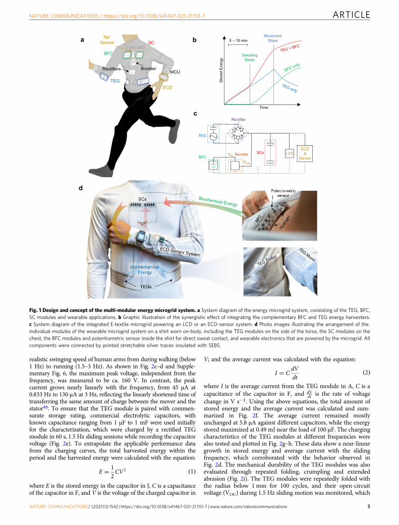
Inspired by this notion, we herein propose and demonstratethe concept of a wearable e-textile microgrid system: a multi-module, textile-base system with applications powered by com-plementary and synergistic energy harvesters and commensurateenergy storage modules. To demonstrate this concept, we describein the following section an integrated e-textile microgrid systemthat unite BFCs and TEGs, two harvesters with distinct andcomplementary energy conversion mechanisms based on humanactivities, along with SC modules for regulating the powering ofwearable applications with both low and high power demand(Fig. 1a). Among many proposed integrated harvesters, thepairing of the biomechanical and biochemical harvesters isdesirable as they rely solely on human activities. Previous studiesdemonstrated only such combination working in proof-of-concept in-vitro settings, hence are challenging to be employedfor real-life scenarios39–41. Adapting the microgrid design con-cept, this work seamlessly integrates biomechanical and bio-chemical harvesters along with energy storage devices, withcarefully budgeted energy rating, into one e-textile platform.When this microgrid harvests energy during human movements,the TEG storage modules are firstly activated from the instantmotion-induced charge generation to harvest biomechanical
energy to rapidly boot the system, while the subsequently acti-vated BFCs harvest biochemical energy from electroenzymaticreactions of sweat metabolites for prolonged power delivery(Fig. 1b). The complementary relationship between the twobioenergy harvesters thus compensates for the limitations of theBFCs due to delayed perspiration and of the TEGs due to the lackof motion. The SC modules regulate low-current, high voltageinputs from the TEG modules and high-current, low-voltageinputs from the BFC modules, with optimal capacity to deliverysufficient power for designated applications while maintainingfast booting. The optimized system can thus boot quickly within3 min to continuously power a microwatt-rated wristwatch withliquid crystal display (LCD), or a milliwatt-rated sensor-electro-chromic display (ECD) system operating in pulsed sessions, andextend their operation to over 30 min in connection to a 10-minmovement session (Fig. 1c). Compared to the early integratedwearable energy systems, the present system relies solely onenergy inputs from human activities and hence is not dependenton the external environment24,28,29. The performance of theindividual modules was characterized, and the energy carefullybudgeted to ensure that the limited amount of harvested energywas efficiently utilized. For compatibility with the wearable formfactor, all modules are printed, textile-based, durable and flexible,and can be readily integrated onto a shirt to harvest energy fromthe sliding motion between the forearms and the torso by TEGsand the sweat generated above the chest by the BFCs (Fig. 1d).These modules are connected with flexible printed silver inter-connections that are secured and insulated by a hydrophobic,water-proof polystyrene-polyethylene-polybutylene-polystyrene(SEBS) block copolymer. The placement of the modules ensuresthe optimal collection of biomechanical energy via the TEGmodule from the arm movements, along with an intimate contactof BFCs to the skin for sweat collection. The placement of BFCsand SCs on the chest also minimizes the possible bending andwrinkling deformation which may affect their energy harvestingand collection efficiency. Implementing the “complementary,commensurate, compatible” design principles, the microgrid e-textile system serves as an attractive example for future integratedon-body systems that are autonomous, reliable, synergistic, sus-tainable and energy-efficient. While the microgrid concept isintroduced here to the field of wearable electronics using com-plementary BFC and TEG bioenergy harvesters paired with SCstorage modules, it can be applied for guiding the development offuture miniaturized energy systems based on a judicious selectionand integration of different modules toward a variety of self-powered electronics applications.
ResultsCharacterization of the microgrid modules. TEGs have beenselected as the biomechanical energy harvesters in this wearablemicrogrid system due to their instant response to motions to gen-erate energy. Since their inception in 2012, TEGs have become themost studied wearable mechanical energy harvesters due to itssimple generation mechanism and the abundant selection ofmaterials10,42. The present TEG module is composed of a poly-tetrafluoroethylene (PTFE)-based negative mover and anethylcellulose-polyurethane (EC-PU)-based positive stator ininterdigitated patterns (Fig. 2a and Supplementary Fig. 1), and isdesigned to harvest energy from sliding motions as illustrated inFig. 2b43–45. To ensure the compatibility of the fabrication of theTEG elements to the e-textile platform with abundant flexibility anddurability, each individual layer in the TEG was formulated into ascreen-printable ink with elastomeric binder that is water-proof andresistant to abrasion. The TEG modules were characterized at lowsliding frequencies ranging from 0.833 Hz to 3 Hz, simulating the
ARTICLE NATURE COMMUNICATIONS | https://doi.org/10.1038/s41467-021-21701-7
2 NATURE COMMUNICATIONS | (2021) 12:1542 | https://doi.org/10.1038/s41467-021-21701-7 | www.nature.com/naturecommunications
realistic swinging speed of human arms from during walking (below1 Hz) to running (1.5–3 Hz). As shown in Fig. 2c–d and Supple-mentary Fig. 6, the maximum peak voltage, independent from thefrequency, was measured to be ca. 160 V. In contrast, the peakcurrent grows nearly linearly with the frequency, from 45 μA at0.833 Hz to 130 μA at 3 Hz, reflecting the linearly shortened time oftransferring the same amount of charge between the mover and thestator46. To ensure that the TEG module is paired with commen-surate storage rating, commercial electrolytic capacitors, withknown capacitance ranging from 1 μF to 1 mF were used initiallyfor the characterization, which were charged by a rectified TEGmodule in 60 s, 1.5 Hz sliding sessions while recording the capacitorvoltage (Fig. 2e). To extrapolate the applicable performance datafrom the charging curves, the total harvested energy within theperiod and the harvested energy were calculated with the equation:
E ¼ 12CV2 ð1Þ
where E is the stored energy in the capacitor in J, C is a capacitanceof the capacitor in F, and V is the voltage of the charged capacitor in
V; and the average current was calculated with the equation:
I ¼ CdVdt
ð2Þ
where I is the average current from the TEG module in A, C is acapacitance of the capacitor in F, and dV
dt is the rate of voltagechange in V s−1. Using the above equations, the total amount ofstored energy and the average current was calculated and sum-marized in Fig. 2f. The average current remained mostlyunchanged at 5.8 μA against different capacitors, while the energystored maximized at 0.49 mJ near the load of 100 μF. The chargingcharacteristics of the TEG modules at different frequencies werealso tested and plotted in Fig. 2g–h. These data show a near-lineargrowth in stored energy and average current with the slidingfrequency, which corroborated with the behavior observed inFig. 2d. The mechanical durability of the TEG modules was alsoevaluated through repeated folding, crumpling and extendedabrasion (Fig. 2i). The TEG modules were repeatedly folded withthe radius below 1mm for 100 cycles, and their open-circuitvoltage (VOC) during 1.5 Hz sliding motion was monitored, which
a
d
b
Sto
red
Ene
rgy
Time
Sweating Starts
Movement Stops 5 – 10 min
c
MCU
SC
ECD
BFC
TEG
Na+ Sensor
Rectifiers Booster
TEG
BFC
Rectifier
Booster Vin
Vout
SCs LCD ECD &
Sensor
Fig. 1 Design and concept of the multi-modular energy microgrid system. a System diagram of the energy microgrid system, consisting of the TEG, BFC,SC modules and wearable applications. b Graphic illustration of the synergistic effect of integrating the complementary BFC and TEG energy harvesters.c System diagram of the integrated E-textile microgrid powering an LCD or an ECD-sensor system. d Photo images illustrating the arrangement of theindividual modules of the wearable microgrid system on a shirt worn on-body, including the TEG modules on the side of the torso, the SC modules on thechest, the BFC modules and potentiometric sensor inside the shirt for direct sweat contact, and wearable electronics that are powered by the microgrid. Allcomponents were connected by printed stretchable silver traces insulated with SEBS.
NATURE COMMUNICATIONS | https://doi.org/10.1038/s41467-021-21701-7 ARTICLE
NATURE COMMUNICATIONS | (2021) 12:1542 | https://doi.org/10.1038/s41467-021-21701-7 | www.nature.com/naturecommunications 3

has shown no discernible change (Fig. 2j). The TEG modules werealso crumpled randomly and flattened repeatedly for 100 times,with their VOC when sliding monitored. The crumpling defor-mation had also shown no change in performance (Fig. 2k). Thedurability of the module against constant friction and washing wasalso tested, where the TEG module underwent constant slidingmotion for over 2000 cycles and 20-min washing, where no visibledrop in VOC was observed (Fig. 2l and Supplementary Fig. 21).The TEG modules could thus be considered a flexible and durablebiomechanical energy harvest and were ready for integration. SeeSupplementary Note 1 and Supplementary Figs. 2–5 for thedetailed device optimization, method of characterization, andperformance calculation of the TEG.
In the wearable microgrid system, BFCs offer the feature ofharvesting biochemical energy continuously from metabolitespresent in biofluids via electroenzymatic reactions. Due to thehigh lactate concentrations in human sweat, a variety of sweat-based BFCs have been developed as wearable energy harvest-ers47–51. The wearable BFC modules were also screen-printedusing various ink composites onto textile substrates. Carbonnanotubes (CNT)-based pellets were attached to interdigitated“island-bridge” interconnections (Fig. 3a-b and SupplementaryFig. 8) composed of flexible carbon composite as currentscollectors and flexible silver composite as conductive intercon-nections. As illustrated in Fig. 3c, such bioenergy harvesting relies
on the oxidation of lactate catalyzed by the lactate oxidase (LOx)immobilized on the bioanode, and on the oxygen reductionreaction facilitated by bilirubin oxidase (BOx) on the cathode. Forefficient sweat bioenergy harvesting, the anode CNT pellets werepreloaded with the 1,4-naphthoquinone (NQ) mediator whileconfining LOx with the glutaraldehyde (GA) cross-linker andchitosan; the CNT-based cathode pellets were decorated withprotoporphyrin IX (PPIX) as the electron transfer promoter52,while immobilizing the BOx with Nafion. The detailed fabricationand composition of the anode and cathode pellets are described inthe “Methods” section and Supplementary Notes 2. All in-vitrotests for characterization of the BFC were carried out in 0.5 Mphosphate buffer solution (PBS) with pH of 7.4. Traditionally,wearable BFC devices are characterized with LSV, with scanrate near 5 mV s−1, 11,16,49,52,53. However, for high-surface-areaelectrodes like the CNT pellets such high-speed LSV will result inan unrealistically high power due to the capacitive currents(Supplementary Fig. 11). Therefore, the fabricated BFC moduleswere characterized using chronoamperometry (CA) at differentpotentials in the presence of 15 mM lactate to reflect the realisticpower output of the BFC in extended discharge sessions. Thetesting of the BFC modules resulted in a maximum power of21.5 μW per module when discharging the BFC at 0.5 V(Fig. 3d–e). The response of the BFC to different lactateconcentrations has been evaluated using CA, as shown in Fig. 3f,
a
PTFE
Flexible Silver
Textile EC/PU
SEBS
EC/PU b c d
e f g h
Before crumpling After crumpling
0 2 4 6 8 10 -200
-100
0
100
200
Vol
tage
(V)
Time (s) 0 500 1000 1500 2000
-200
-100
0
100
200
Vol
tage
(V)
Cycles
f = 1.5 Hz Before folding After folding
0 2 4 6 8 10 -200
-100
0
100
200
Time (s)
Vol
tage
(V)
i j k l
0 5 10 15 20 25
-100
Time (s)
-200
0
100
200
Vol
tage
(V)
0.83 Hz 1 Hz 1.5 Hz 2 Hz 3 Hz
Time (s) 0 5 10 15 20 25
-150
-75
0
75
150
Cur
rent
(μA
)
0.83 Hz 1 Hz 1.5 Hz 2 Hz 3 Hz
1 μF 10 μF 100 μF 220 μF 470 μF 1000 μF
100 101 102 103
0.0
0.2
0.4
0.6
Capacitance (μF)
Sto
red
ener
gy (m
J)
0
2
4
6
8
10
Ave
rage
cur
rent
(μA
) f = 1.5 Hz
0.5 1.0 1.5 2.0 2.5 3.0 0.0
0.5
1.0
1.5
2.0
Frequency (Hz)
Sto
red
Ene
rgy
(mJ)
0
2
4
6
8
10
A
vg. C
urre
nt (μ
A)
C = 100 μF 0.83 Hz 1 Hz 1.5 Hz 2 Hz 3 Hz
0 10 20 30 40 50 60 0
1
2
3
4
5
Vol
tage
(V)
Time (s)
0 10 20 30 40 50 60 0
1
2
4
5
Vol
tage
(V)
Time (s)
3
Folded
Crumpled
Flexible silver PTFE EC / PU
Sliding
e-
e-
Fig. 2 Characterization of the performance of the TEG module. a Schematic image of the layer-by-layer composition of the textile-based TEG modulecomposed of a PTFE-based mover (top) and an EC-PU-based stator (bottom). b The charge generation mechanism of the TEG module under in-planefriction between the mover and the stator. The unrectified output peak voltages (c) and peak currents (d) of the TEG at different sliding frequencies. Thecharging of commercial capacitors with difference capacitance at 1.5 Hz in a 60-s period (e) and the corresponding stored energies and equivalent averageDC currents (f). The charging of 100 μF capacitor at different frequencies in a 60-s period (g) and the corresponding stored energies and equivalentaverage DC currents (h). i Images of folded and crumpled TEG stator. Scale bar, 1 cm. The unrectified output peak voltages before and after 100 cycles offolding (j) and crumpling (k). l The long-term electrical signal from the TEG module under continuous sliding motions with the frequency of 1.5 Hz.
ARTICLE NATURE COMMUNICATIONS | https://doi.org/10.1038/s41467-021-21701-7
4 NATURE COMMUNICATIONS | (2021) 12:1542 | https://doi.org/10.1038/s41467-021-21701-7 | www.nature.com/naturecommunications

Supplementary Figs. 12 and 13, where the power per moduleincreases from 9.7 μW at 5 mM lactate to 25.3 μW at 25 mMlactate. The mechanical durability and the stability of the BFCwere also tested using CA. The module was bent 1000 times to180° inward then outward with the radius of 1.3 cm (Fig. 3g), withthe current at 0.5 V before and after bending in 10 mM lactateenvironment measured. As shown in Fig. 3h, the power of theBFC did not show any noticeable change before and after thebending. Such resiliency is attributed primarily to the “island-bridge” structure where the non-flexible, functional electrodepellets as the islands are connected by flexible, conductive silverinterconnections. The stability of the BFC was tested alsothroughout the week (as shown in Supplementary Fig. 14). TheBFC under test was stored in refrigerator under 4 °C and wastaken out for testing every 24 h in a 10 mM lactate environment.The results of the individual CA measurements are summarizedin Fig. 3i. Additional details of the fabrication and characteriza-tion of the BFC module, including its washability and stability insimulated sweat conditions, can be found in SupplementaryNote 2 and Supplementary Figs. 7-11, 15, and 21.
Flexible, printed SCs are selected for its ability to charge anddischarge repeatedly and rapidly to deliver a flexible range ofpowers—a feature highly desirable for fast booting and pulsedhigh-power applications. A CNT and poly(3,4-ethylene dioxythio-phene) polystyrene sulfonate (PEDOT:PSS) hybrid capacitor,offering screen-printability and high flexibility, has been adoptedas symmetrical interdigitated electrodes that are connected byflexible silver current collectors (Fig. 4a and SupplementaryFig. 15)54. Each SC module consists of 5 SC units connected inseries to reach the desired 5 V voltage range for directly powering
electronics, with each SC unit featuring four interdigitated CNT-PEDOT:PSS electrode segments covered by a solidified, trans-parent, flexible, sulfuric acid-crosslinked polyvinyl alcohol(PVA) electrolyte (Fig. 4b and Supplementary Fig. 16). Thehybrid capacitor stores electric energy via both double-layercapacitance endowed by the high specific surface area CNTs andpseudocapacitance from the PEDOT:PSS, as illustrated in Fig. 4c.The areal capacitance of the printed SC material was character-ized via both cyclic voltammetry (CV) at different scan rates andgalvanostatic charge-discharge (GCD) with different currents.The GCD was conducted at charge/discharge between 0 V and1 V with currents at 25, 50, 100, 250, and 500 μA (Fig. 4d). Thecapacitance at discharge is used to gauge the capacitance of theSC unit, which is calculated using the equation:
C ¼ IΔtAðEf � EiÞ ð3Þ
where C is the areal capacitance in F cm−2, I is the current in A,Δt is the time taken for the discharge, A is the geometric area ofelectrodes, Ef is the charged potential in V, and Ei is thedischarged potential in V. CV was carried out with the scan ratesof 5, 10, 25, 50, 100 mV s−1 between the window of 0 V and 1 V(Fig. 4e). The areal capacitance is calculated using the formula:
C ¼ 12νAðEf � EiÞ
Z Ef
Ei
I dV ð4Þ
where C is the areal capacitance in F cm−2, ν is the scan rate inV s−1, A is the geometric area of electrodes in cm2, Ef is thehigher vertex potential in V, Ei is the lower vertex potential in V,
BFC
Cathode (+) Anode
(-)
Textile
FlexibleSilver
SEBS
a b c
0.2 0.3 0.4 0.5 0.6
0
8
16
24
EBFC (V)
[Lactate] = 15 mM
0 2 4 6 8 10 0
8
16
24
32
40
Pow
er (μ
W)
Time (min)
0 mM
10 mM 15 mM 20 mM 25 mM
5 mM
1 2 3 4 5 6 7
0
8
16
24
Pow
er (μ
W)
Time (day)
[Lactate] = 10 mM
0 2 4 6 8 10 0
8
16
24
32
40 P
ower
(μW
)
Time (min)
Before Bending After Bending
d e f
g h i
NQ(red) NQ(ox)
H2O O2
PPIX
BOx
LOx CNT BOx
Anode Cathode
Lactate Pyruvate
e- e-
Load
LOx
CNT-BOx-PPIX
CNT-NQ -LOx
0 2 4 6 8 10 0
Time (min)
8
16
24
0.64 V 0.25 V
Pow
er (μ
W)
Pow
er ( μ
W)
Fig. 3 Characterization of the performance of the BFC module. a Schematic image of the textile-based BFC module composed of eight BOx-basedcathodes and two LOx-based anodes connected by printed flexible interconnections. b A zoomed-in photo image of the fabricated BFC module. Scale bar,5 mm. c The charge generation mechanism of the BFC from lactate and oxygen in sweats. d The output power of the BFC module at different dischargepotentials with 15 mM lactate concentration. e The equivalent polarization curve derived from (d). f The output power of the BFC module discharged at0.5 V under various lactate concentrations. g Image of the BFC module under 180° outward bending. Scale bar, 1 cm. h The power of the BFC modulebefore and after the 1000 bending cycles. i The output power of the BFC module with 10mM lactate concentration everyday within a week.
NATURE COMMUNICATIONS | https://doi.org/10.1038/s41467-021-21701-7 ARTICLE
NATURE COMMUNICATIONS | (2021) 12:1542 | https://doi.org/10.1038/s41467-021-21701-7 | www.nature.com/naturecommunications 5

and the I is the current in A. As agreed by both characterizationmethods, the capacitance of the printed SC was determined to beca. 10 mF cm−2 (Supplementary Fig. 17). Several SC modulescan be connected in series or in parallel to adjust the overallcapacitance to fit for harvesters and applications to obtainoptimal charging speed and deliver sufficient energy (Fig. 4f).The stability of the module is analyzed by performing GCDcycles on the SC module. The mechanical stability of the modulewas evaluated by applying 1000 cycles of repeated inward-outward bending cycles at 180° with a bending radius of 0.5 cm(Fig. 4g). As shown in Fig. 4h, the charge-discharge behavior ofthe SC does not show any noticeable change before and after the1000 cycles of bending deformation, suggesting the robustflexibility of the SC module for wearable applications. To preventthe leaching of the acidic electrolyte, the device is sealed by anadditional layer of printed SEBS. The device can thus withstandextended wetting and washing without electrolyte leaching orobservable degradation in its performance (SupplementaryFig. 21). The electrochemical stability of the SC module wasstudied by 1000 cycles of GCD between 0 V and 5 V with acurrent of 50 μA. As demonstrated in Fig. 4i, the arealcapacitance of the SC shows a slight drop of areal capacitanceafter 1000 cycles to ca. 9 mF cm−2, while the coulombic
efficiency gradually increases to 95%. The electrochemicalperformance of the SC is thus acceptable within the use-case ofthe microgrid, where roughly a few hundreds of charge-dischargecycles are expected. Detailed characterization and calculation ofthe SC performance are described in Supplementary Note 3 andSupplementary Figs. 18-19. Overall, each SC module was ratedwith the capacitance of ca. 150 μF.
Synergistic bioenergy harvesting. To demonstrate the synergisticeffect of between TEG modules and BFC modules, a typicalactivity session has been simulated by applying constant 1 Hz–1.5Hz sliding motions and spiking of 10–15 mM lactate fuel. Usingthis setting, three scenarios have been simulated: (i) movementstarts followed by the start of perspiration; (ii) movements andperspiration taking place simultaneously; and (iii) movementsstop but the perspiration continues. In the 4-min simulations, twoTEG modules rectified by a bridge rectifier and one BFC modulemodulated by a DC voltage booster were used to charge one SCmodule (Supplementary Fig. 21). Each scenario was tested withonly the TEG (blue curve), only the BFC (green curve), and bothmodules operating together (red curve). As shown in Fig. 5a,during the starting phase, the TEG module was able to charge the
+ + +
-- -
+ + +
-- -+ + ++ + +
+ + +
- --
- --- --
- --
+ + +
Cathode(+)
Anode(-)
SC
FlexibleSilver
Textile
SEBS
0 1 2 3 4 50
1
2
3
4
5
E SC
(V
)
Time (min)
i iii
0 75 150 225 300
0.00
0.25
0.50
0.75
1.00
E SC
(V)
Time (s)
500 μA 25 μA
0.0 0.2 0.4 0.6 0.8 1.0 1.2
-0.2
-0.1
0.0
0.1
0.2100 mV s-1
Cur
rent
(mA
)
ESC (V)
5 mV s-1
0 250 500 750 1000
0
4
8
12
16
C(m
F cm
-2)
Areal CapacitanceCoulombic Efficiency
Cycles
0
20
40
60
80
100
CE
(%)
I = 50 μA
0 1 2 3 4 5 6
0
1
2
3
4
5
E SC
(V)
Time (min)
BeforeAfter
a b c
d e f
g h i
CNT-PEDOT:PSSElectrodes
PVA Electrolyte
Fig. 4 Characterization of the performance of the SC modules. a Schematic image of the textile-based SC energy storage module consisting of currentcollectors, CNT-PEDOT:PSS-based electrodes and PVA-based solid gel electrolyte. Each module is composed of five SC units connected in series.b The photo image of the printed SC module. Scale bar, 5 mm. c The charge storage mechanism of the hybrid SC unit based on both the double-layercapacitance and pseudocapacitance. d GCD with currents of 25, 50, 100, 250, and 500 μA of a SC unit from 0 V to 1 V. e CV with scan rates of 5, 10, 25,50, 100mV s−1 from 0 V and 1 V of a SC unit. f GCD of the energy storage modules with different configurations, with (i) two storage modules in series;(ii) one storage module; and (iii) two storage modules in parallel. g Images of the inward and outward bending of the SC module. Scale bar, 1 cm. h 5 μAGCD of the SC module before and after 1000 cycles of 180º bending deformation. i The areal capacitance and coulombic efficiency of a SC unit in 1000charge-discharge cycles.
ARTICLE NATURE COMMUNICATIONS | https://doi.org/10.1038/s41467-021-21701-7
6 NATURE COMMUNICATIONS | (2021) 12:1542 | https://doi.org/10.1038/s41467-021-21701-7 | www.nature.com/naturecommunications

0 1 2 3 4
E SC (V
)
2
3
4
5
a
Starting Ending During
0 Stop Sliding
Add Lactate
Start Sliding
b
0 5 10 15 20 25 30
0
2
4
6
E SC (V
)
C = 75 μF
0 5 10 15 20 25 30 Time (min)
TEG only
BFC only
TEG + BFC
C = 150 μF
0 5 10 15 20 25 30
C = 300 μF
c
0 5 10 15 20 25 30
2
3
4
5
E SC (V
)
Time (min)
____ TEG Only ____ BFC Only ____ BFC + TEG
Vmax Cutoff
Stop Movement
BFC Activated
C = 150 μF f ≈ 1.5 Hz
Stop Movement
Start Sweating (5 ~ 7 mins)
Start Movement
d
Exercising & Sweating Exercising Sweating
Booster Activated
(i) (iii) (ii)
Sliding & Lactate Sliding Only Lactate Only C = 150 μF
ES
C (V
) 4
0 1 2 3
2
3
4
5
0 1 2 3 4 0 1 2 3 4 Time (min)
(i) (iii)
f = 1 Hz, [Lactate] = 10 mM
Time (min) 0 1 2 3 4
ii
0 1 2 3 4
2
3
4
5
0 1 2 3 4
E SC (V
)
(iv) (vi) (v)
f = 1.5 Hz, [Lactate] = 10 mM
(vii) (viii)
f = 1.5 Hz, [Lactate] = 15 mM
(viii)
0 1 2 3 4 Time (min)
0 1 2 3 4
(ix)
____ TEG Only ____ BFC Only ____ BFC + TEG
(ii)
Fig. 5 In-vitro and on-body charging performance of the wearable bioenergy microgrid system. a In-vitro charging curves of the individual and integratedharvester with (i)-(iii) 1 Hz frequency and 10 mM lactate; (iv)-(vi) 1.5 Hz frequency and 10 mM lactate; and (vii)-(ix) 1.5 Hz and 15 mM lactate for the TEGmodules and the BFC modules, which simulate three representative phases: starting ((i), (iv), and (vii)), exercising((ii), (v), and (viii)) and ending((iii), (vi),and (ix)) of an activity session. b Photo illustration of the on-body testing arrangement. c On-body charging of a 150 μF SC using the individual BFC or TEGmodule alone, and with both modules combined, in a 10-min exercise session followed by a 20-min resting. d On-body charging of capacitors from SCswith (i) 75 μF, (ii) 150 μF, and (iii) 300 μF from 0 V in a 30-min exercise session to represent the charging of the system including the cold-starting phaseof the voltage-booster. During the 30-min period, movement stops once the SC if fully charged to 5.1 V.
NATURE COMMUNICATIONS | https://doi.org/10.1038/s41467-021-21701-7 ARTICLE
NATURE COMMUNICATIONS | (2021) 12:1542 | https://doi.org/10.1038/s41467-021-21701-7 | www.nature.com/naturecommunications 7

SC module immediately after starting the movement, whereas theBFC module was not able to provide power due to the lack oflactate. When lactate was spiked, the BFC started to respond tothe fuel addition to provide power to the SC. The additive effectof integrating two complementary energy harvesters can beobserved throughout the rest of the simulation, where theircharging speed surpasses the individually operating harvesters.Such additive effect continued throughout the scenario (ii) andthe first half of the scenario (iii). As soon as the sliding motionstopped, the TEG module stopped its operation instantaneously.In contrast, the BFC module continued to operate due to thepresence of the lactate fuel to charge the SC module withoutinterruption. Beyond the additive effects of two energy harvesters,the advantage of integrating the complementary TEG and BFCmodules was demonstrated: at the start of the movement, the fast-booting TEG module can compensate for the slow-booting of theBFC; in return, the transiently harvesting TEG module wascompensated by the extended-operating BFC module after themovement stops, as illustrated in Fig. 1b. This synergistic beha-vior, not offered by any previous studies, is highly desirable forthe reliable and sustainable operation of a self-powered wearablesystem. As expected, the charging speed of the 1 Hz sliding,10 mM lactate simulation condition (Fig. 5a(i)-(iii)) was theslowest amongst all three, followed by the 1.5 Hz sliding, 10 mMlactate condition (Fig. 5a(iv)-(vi)), with the 1.5 Hz sliding, 15 mMlactate condition charging the capacitor fastest (Fig. 5a(vii)-(ix)).In all three situations, the synergistic additive effect was observedin all 3 phases of the condition, and the complementary fast-boosting and extended-harvesting effects were observed for thestarting and ending phases of all 3 conditions, correspondingly.
The synergistic effect of the integrated energy harvesting wasfurther characterized with on-body tests to gauge the optimalcapacitance that can mostly reflect such complementary fast-booting and extended-harvesting effects. Two TEGs, two BFCsand the corresponding SC modules were printed on the left andright sides of the waist, below the collar and in front of a shirt,respectively, as shown in Fig. 1c, and were connected via printedsilver traces and enameled wires with proper insulations. A PVA-based PBS hydrogel was applied onto the BFC module for sweatcapturing. A 10-min exercise session was carried out on a cyclingmachine, as illustrated in Fig. 5b, where the arm-swingingfrequency was kept near 1.5 Hz, followed by 20 min of resting.Similar to the in-vitro simulation, the integrated on-body systemwas tested with only TEG, only BFC and with all harvestersoperating together. Figure 5c demonstrates the on-body energyharvesting performance of the integrated system. For the systemoperating solely on TEG modules, the energy harvesting startedimmediately after the arm-swinging started and charged the SCmodule continuously throughout the 10-min exercise session. Assoon as the movement stopped, the TEG stopped supplyingpower, and the SC module slowly self-discharged. For the systemoperated solely on the BFC module, the system suffered fromslow booting with a 6-min delay. However, the BFC was able tosupply power to the SC module quickly after sweating started,and fully charged the SC within 17 min Upon stopping theexercise, the BFC module was able to continuously supply powerto the SC module over a 30-min period, reflecting the continuouspresence of sweat. Lastly, the integrated system was able tocompensate for both the slow booting and the transientharvesting, quickly fully charging the SC module in 7 min,maintaining maximum voltage over a 30-min period. In additionto the data presented in Fig. 5c, the on-body operation of thesystem was also tested with SC modules configurated with thecapacitance of 75 μF, 150 μF, and 300 μF (Fig. 5d). The chargingis started at 0 V instead of 2 V to demonstrate the booting of thevoltage booster in the start of the operation. The SC modules were
fully discharged to 0V and their potential monitored duringcharging, and the exercise sessions were only stopped when the SCis fully charged to 5.1 V or the limit of 30min was reached. Asshown in the figure, the time taken to fully charge the SC moduleincreased as the capacitance increased for both the individualharvesters and the integrated microgrid harvesters. The synergisticand complementary behavior can still be observed in the bootingphase of the charging, where the integrated harvesting system canfully charge the SC module faster than the individual harvesters,starting from the 4min for 75 μF capacitor, to the 8 min for 150 μFcapacitor and 12min for the 300 μF capacitor. These results havethus validated the in-vitro simulation, fully illustrating thecomplementary and synergistic behaviors of the wearable micro-grid system which offers fast-booting and extended-harvesting forenergy harvesting in an activity session. Additional experimentaldetails, data and discussion regarding the in-vitro and on-bodytests can be found in Supplementary Note 4.
Two wearable applications were selected as examples of twooperating modes for demonstrating the potential and advantages ofthe wearable microgrid system (Fig. 6a). The SC is an attractiveenergy storage module owing to its flexible discharge rates that allowpowering of either low-power application continuously or of high-power application in a brief, pulsed fashion without damaging themodule. For efficiently use the limited energy stored in the SCmodules, the power consumption of the applications wascharacterized, and the SC modules were configured with minimumbut sufficient capacitance for rapid booting while ensuring successfuloperation. Detailed fabrication and characterization procedures,additional data and further discussions can be found in Supplemen-tary Notes 5 and Supplementary Figs. 22–31.
A textile-based sodium ion (Na+) sensor integrated with awearable, flexible ECD pixeled display was developed as anexample for applications with higher power demand operating inpulsed mode. The developed potentiometric Na+ sensor exhibiteda near-Nernstian response to the concentration of the Na+ target,with a potential change of 57.19 mV per decade of concentrationchange (Fig. 6d and Supplementary Fig. 23). The sensor outputcan be instantly read by the pre-programmed integrated circuitand reported by changing the color of individually controlledECD pixels, as illustrated in Fig. 6c and Supplementary Movie 2.The operation of the ECD pixels follows the simple reversibleredox reaction of the PEDOT:PSS,
PEDOTþPSS� þ Naþ þ e� $ PEDOT0 þ NaþPSS� ð5Þthat takes place when a voltage above +1 V is applied to the back-panel electrodes, and the reduction reaction take place on thefront panel and turn its color from light blue to dark blue(Supplementary Movie 1). A low-power microcontroller unit(MCU) was selected for reading the input from the Na+ sensorand controlling the on/off of the individual ECD pixels. The ECDis able to refresh rapidly and maintain the display without acontinuous supply of power.
The set-up of the microcontroller is illustrated in Supplemen-tary Fig. 28. The controller was pre-programmed to displaypotential up to 0.32 V, with each ECD pixel corresponding to one0.04 V increment of the sensor output. The power consumptionof the microcontroller connected to the sensor-ECD system wasmeasured similarly using the potentiostat set at different voltage,as demonstrated in Supplementary Fig. 29. As shown, the powerconsumption of the microcontroller exceeded the wristwatch by 3orders of magnitude, ranging from 4 mW at 2 V to 30 mW at 5 V.Yet, the microcontroller was able to boot quickly within the first50 ms, take readings and apply signals to the ECD pixels withinthe first 200 ms, which allow this system to be poweredtransiently from the discharge of one charged capacitor. Theenergy consumed by one discharge session can be estimated by
ARTICLE NATURE COMMUNICATIONS | https://doi.org/10.1038/s41467-021-21701-7
8 NATURE COMMUNICATIONS | (2021) 12:1542 | https://doi.org/10.1038/s41467-021-21701-7 | www.nature.com/naturecommunications

the equation:
E ¼ P ´ t ð6Þwhere E is the energy in J, P is the power in W, and t is the time ins. To supply 200 ms of operation assuming the lowest power ofca. 4–5 mW, the energy required was thus estimated to be ca.0.8–1 mJ. Capacitors ranging from 100 μF to 470 μF were able tosupply sufficient energy to the microcontroller in one continuousdischarge session with the larger capacitors had shown nosubstantial extended operation time (Supplementary Fig. 29b).The capacitors were discharged with 200 ms pulsed discharge,where more differences were more pronounced. The highercapacitance capacitors were able to sustain multiple refreshsessions, and the number of sessions decreases with thecapacitance, as to 1 successful discharge session from the 100μF with a slightly excess amount of energy, and 1 discharge fromthe 47 μF capacitor which did not last throughout the entire 200ms session (Supplementary Fig. 29c). It is thus determined thatthe 75 μF SC modules should retain enough energy to sustain one
complete refresh session. The required state of charge of the SCwas then characterized by charging the 75 μF SC module todifferent potentials, and use the SC to power one refresh session,while the color on the ECD recorded to determine the minimumstate of charge required for the 75 μF SC module to induce colorchange with sufficient contrast (Supplementary Fig. 30). It can beobserved that the contrast of the on and off pixels graduallydecreased with the initial state of charge of the SC modules, withthe difference barely recognizable below 3.5 V. The minimumpotential of 4 V before initiating a refresh session was thusdecided. To confirm with the calculation above on the energyrequired for one operation session, the energy stored in thecapacitor was calculated using equation:
ESC ¼ 12C V2
i � V2f
� �ð7Þ
where ESC is the energy discharged from the SC in J, C is thecapacitance of the SC in F, Vi
2 is the potential of the SC before thedischarge in V, and Vf
2 is the potential of the SC after the
a b
c
f
LCD watch
Electrochromic display (ECD)
0.00V
0.04V
0.08V
0.12V
0.16V
0.20V
0.24V
0.28V
0.32VVIN =
2.0 V 2.5 V 3.0 VESC = 4.0 V
e
Na+ Sensor
ISE
S = 57.19 mV/log [Na+]R2 = 0.99716
0.1 1 10 1000.05
0.15
0.25
Log [Na+]
E (V
)
d
10 min
6 min
2 min
0.0
2.5
5.0
0.0
2.5
5.0
0 5 10 15 20 25 30
0.0
2.5
5.0
ES
C(V
)
Time (min)
2 min
BFC
TEG
BFC + TEG
Start Sweating
0 3020 10 Time (min)
C = 75 μFStart Movement Stop Movement
LCD Visible
LCD OFF
LCD Visible
LCD Visible
Start Sweating
0 3020 10 Time (min)
Start Movement Stop Movement
0.0
2.5
5.0
0 5 10 15 20 25 30
0.0
2.5
5.0
ES
C(V
)
BFC
0.0
2.5
5.0
BFC + TEG
Time (min)
7 min
2.5 min
3 min
10 min
C = 75 μF
Sensor Refresh
TEG
MCU
SEBS Insulation
RE
Fig. 6 Wearable bioenergy microgrid system with different applications. a Image of the LCD wristwatch and the ECD for the Na+ potentiometric sensor.Scale bar, 1 cm. b Images of the LCD screen with different input voltages. c The display of the ECD with different sensor voltage input. d The photo image ofthe all-printed flexible potentiometric sensor (top) and the calibration curve of the Na+ sensor (bottom). Scale bar, 2 mm. e-f Voltage vs. time curves of thewearable microgrid system powering the Na+ sensor-ECD system in pulsed mode during a 10-min running session followed by 20min of rest, with only theBFC module operating, only the TEG module operating, and both harvesters operating together (e); and the LCD wristwatch continuously during a 7-minrunning session followed by 23min of rest (f).
NATURE COMMUNICATIONS | https://doi.org/10.1038/s41467-021-21701-7 ARTICLE
NATURE COMMUNICATIONS | (2021) 12:1542 | https://doi.org/10.1038/s41467-021-21701-7 | www.nature.com/naturecommunications 9

discharge in V. For a 75 μF SC to discharge from 4 V to 1.25 V,the energy released from the discharge is thus calculated to be0.88 mJ, which agreed with the previous calculation based on Eq.(6). The 75 μF SC modules with a threshold voltage of 4 V wasthus selected to allow fast booting while providing sufficientenergy for a successful sense-refresh session.
The integrated wearable sensor-ECD application was inte-grated into the microgrid and tested on the body in a 10-minexercise session. As shown in Fig. 6e, the SC module was chargedup to 4 V and discharged to refresh the sensor-ECD system. Thefully integrated microgrid system was able to boot quickly within3 min and intermittently refresh the results during the 30-minoperation. In comparison, the BFC module suffered from slowbooting due to delayed perspiration while the TEG modules werenot able to sustain the operation after stopping the movement. Itis worth noting that the faster boosting speed for the TEG-onlyscenario is due to the lack of need to supply a small amount ofenergy to boost the voltage booster. In both applications withdifferent modes of operation, the wearable microgrid system—with its complementary and synergistic BFC-TEG harvesting andcommensurate SC pairing—was able to deliver both fast-bootingand extended-harvesting to ensure the autonomous and sustain-able operation of the wearable platforms.
A low-power wristwatch with a LCD was chosen as arepresentative application that is continuously powered by thewearable microgrid system. The voltage of 2.5 V is determined asthe turn-on threshold voltage, corresponding to the minimumvoltage for the LCD to display with sufficient contrast (Fig. 6b).The power consumption of the watch was rated below 10 μWwhich has low requirement in storage unit (SupplementaryFig. 27). Two SC modules connected in-series with the capacity of75 μF were selected to offer fast booting while maintainingextended operation when the microgrid harvests from humanactivities. Short, 8-min exercise sessions were carried out, with thepotential of the SC recorded continuously. As illustrated inFig. 6f, the simultaneous BFC-TEG energy harvesting was able toquickly boot the wristwatch within 2 min and maintain itscontinuous operation for over 30 min In contrast, the BFC-onlysystem suffered from slow booting while the TEG-only systemcan only maintain the operation for a short time period before theSC module voltage dropped to below 2.5 V.
DiscussionIn summary, we have demonstrated the concept of wearablebioenergy microgrid via a textile-based multi-module system forsequentially harvesting biomechanical and biochemical energy viathe TEG and BFC modules. The microgrid can store and regulatethe harvested energy via efficiently paired SC modules to effi-ciently power wearable applications such as an LCD wristwatchand a sensor-ECD system. Implementing the “compatible, com-plementary, and commensurate” design principles, all moduleswere carefully characterized and efficiently integrated to rapidly,autonomously and sustainably deliver power using the limitedamount of harvested energy. All printed modules, printed withpolymer-based composite inks, are flexible, durable, and ready forseamless integration on textile platforms. Compared to previousintegration of wearable energy harvesting and storage devices, thiswork focuses on the complementary relationship between twobioenergy harvesters that perform synergistically to scavengeenergy from human motion, and their pairing with storagemodules with commensurate capacity for maximized efficiencyand performance. With the optimized pairing of components,such wearable microgrid can quickly boot selected applicationswhile sustaining their operation substantially longer than theexercise sessions, hence ensuring the reliability and practicality of
the wearable system. To further improve such E-textile microgridsystem, more modular design concepts, such as fabricating patch-like detachable and swappable harvesters, storage devices, andsensors, can be adapted to extend the usage and applicable sce-nario of the E-textile system. While serving here as an example,such microgrid strategy inspires future miniaturized integratedsystems that harvest thermal, chemical or mechanical energies toselect complementary, synergistic, commensurate and compatiblecomponents for their designated use case. The configuration ofthe harvesters connection can also be further explored: instead ofparallelly operating harvesters, serial connections between har-vesters of the same type or different types can be considered toincrease the output voltage and minimize or eliminate the needfor voltage regulation. Future work in developing energy har-vesting devices that rely on the harvesting from passive activitieswill broaden the applicable scenarios and enhance the practicalityof the microgrid system. Expanding the microgrid concept fromon-body to in-body applications, and utilizing the abundantamount of biofuel and biomechanical movements within the bodycan also allow integrated harvesting system for self-poweredimplantable or ingestible sensing that are no longer limited byexternal environment or the need for exercise. Upon improvingthe power density of various harvesters, high capacity energystorage options with commensurate rating can also be consideredfor powering of a wider range of electronics for advanced func-tionalities. The concept of wearable microgrids and their designprinciples are thus expected to promote system-level considera-tions for integrating various new-form-factor modules towardstruly self-powered, autonomous, and sustainable systems.
MethodsChemicals and reagents. 1,4‐NQ, bovine serum albumin (BSA), PPIX (≥95%),glutaraldehyde, L(+)-lactic acid, acetic acid, sulfuric acid, chitosan (from shrimpshells, >200 cP, 1 wt. % in 1% acetic acid), silver flakes (10 μm), PTFE powder(powder, free-flowing, 1 μm particle size), toluene, methanol, ethanol, PVA (MW= 89,000 – 98,000, 99+ % Hydrolyzed), polyvinyl butyral (PVB) (powder, >100cps), polyvinyl chloride (PVC), 4-methyl-2-pentanone (MIBK), 1,1,1,2,3,4,4,5,5,5-decafluoropentane (DFP), Poly(sodium 4-styrene sulfonate) (MW ~ 70,000),sodium tetrakis[3,5-bis(trifluoromethyl)phenyl]borate (Na-TFPB), D-sorbitol,dioctyl sebacate (DOS) and glycerol were purchased from Sigma-Aldrich (St. Louis,MO, USA). L-lactate oxidase (LOx) (80 U mg−1) was purchased from Toyobo(Japan). BOx (>1.2 U mg−1) was obtained from Amano Enzyme. Carboxyl-functionalized multi-walled carbon nanotubes (MWCNT‐COOH, Ø = 10-20 nm,10-30 µm length, >95% purity) were purchased from Cheap Tubes Inc. Water-based polyurethane resin Dispercoll U-42 was purchased from Covestro (Ger-many). Tetrahydrofuran (THF) was purchased from EMD Millipore. Ethylcellulose(EC) (Standard 4), polyurethane (PU) (Tecoflex SG-80A) were obtained fromLubrizol Life Sciences. SEBS (G1654) was obtained from Kraton (TX, USA).Fluorinated binder (T-70, a terpolymer of vinylidene fluoride, tetrafluoroethyleneand hexafluoropropylene) was obtained from Frechem (Jiangsu, China). Super-Pcarbon black was purchased from MTI Corporation (Richmond, CA, USA). Gra-phite powder was purchased from Acros Organics (USA). Stretchable textile LycraShiny Milliskin Nylon Spandex Fabric was purchased from Spandex World. Inc(USA). The CapstoneTM fluorosurfactant FS-65 is purchased from DuPont (USA).The graphite carbon paste was purchased from Ercon Inc. (Wareham, MA, USA).The screen printable PEDOT:PSS ink (C2100629D1) was purchased from SunChemical Ltd. (Bath, UK). All metal stencils were designed via Autodesk AutoCAD(CA, USA) and are ordered from Metal Etch Services (San Marcos, CA, USA). Thevoltage booster (Texas Instruments bq25505) and the microcontroller (AtmelAtTiny441) were purchased from Digi-Key Electronics (MN, USA). The wrist-watch (Casio, A178WA-1A) was purchased from Amazon.com (WA, USA).
Formulation of flexible polymer composite Ink. The SEBS resin was prepared bydissolving 4 g of SEBS polymer in 10 mL toluene. The silver ink was made througha method similar to our previous protocol48,55. Briefly, flexible silver composite inkwas formulated by mixing silver flakes with the SEBS resin (weight ratio = 2: 1) bya dual asymmetric centrifugal mixer (Flacktek Speedmixer, DAC 150.1 KV-K) for5 min with a speed of 1800 rotations per minute (RPM). The flexible carboncomposite ink is formulated by mixing super-P powder, graphite powder, SEBSresin, and toluene (weight ratio = 1: 6: 8.4: 2.1) in the mixer for 5 min at 2150RPM. The PTFE ink was formulated by mixing the PTFE powder, T-70, DFP andMIBK (weight ratio = 9: 6: 2: 5) in the mixer for 10 min at 1800 RPM. The EC-PUink was formulated by mixing EC powder, PU and THF (weight ratio = 1: 1: 14) in
ARTICLE NATURE COMMUNICATIONS | https://doi.org/10.1038/s41467-021-21701-7
10 NATURE COMMUNICATIONS | (2021) 12:1542 | https://doi.org/10.1038/s41467-021-21701-7 | www.nature.com/naturecommunications

the mixer for 5 min at 2000 RPM. The CNT-PEDOT:PSS ink for the SC moduleswas formulated by mixing the MWCNT-COOH, PEDOT:PSS paste and fluor-osurfactant (weight ratio = 5: 95: 0.5) in the mixer for 5 min at 2500 RPM. ThePVA-acid electrolyte gel was formulated following our previous work by dissolving1 g of PVA into 10 mL of water, adding 10 g of 1.8 M sulfuric acid and heating withrigorous stirring with a magnetic stir bar on a hot plate at 100 °C until 50 % of thewater has evaporated. The ink formulations for the electrodes and electrolyte usedin the ECD are discussed in detail in Supplementary Note 5.2.
Fabrication of flexible TEG modules. The whole layers of flexible TEG moduleswere mainly made into a 100 μm-thick metal stencil for printing. The stator of theTEG module is fabricated by firstly casting a layer of SEBS lining with the SEBSresin onto the textile substrate using an adjustable doctor blade with a thickness of200 μm and cured in an oven at 65 °C for 10 min Then, the interdigitated silvercurrent collector layer was printed using the flexible silver composite ink and thedesigned metal stencil and cured at 60 °C for 20 min After that, a positively chargedlayer based on EC-PU ink was printed using the doctor blade with a thickness of 50μm and cured at 60 °C for 10 min For mover of the TEG, the EC-PU layer was firstprinted on the surface of the textile using a doctor blade with 100 μm thick andcured at 60 °C for 10 min as lining. And then, interdigitated, negatively chargedlayer was printed using the PTFE ink with the metal stencil and cured at 70 °Cfor 20 min
Fabrication and assembly of BFC modules. The CNT pellets for the electrodewere prepared by formulating a paste that was molded with a thick PTFE stencil.The formulation is modified based on an early publication11. The anode paste wasformulated by blending 7 mg MWCNT-COOH, 2 mg NQ, 11 μL GA (1% inethanol) and 56 mg chitosan solution (3 wt% in 0.1 M acetic acid) with mortar andpestle. The cathode past was formulated by blending 8 mg MWCNT-COOH, 11 μLglutaraldehyde (1 % in water) and 56 mg chitosan solution (3 wt% in 0.1 M aceticacid) with mortar and pestle. The paste was then molded using a PTFE stencil anddried in the oven at 80 °C for 20 min to form pellets.
The design of the BFC current collector array was made into a 100 μm-thickmetal stencil for printing. To fabricate the current collector, a layer of SEBS resinwas firstly cast onto the textile substrate using an adjustable doctor blade with athickness of 200 μm and cured in an oven at 80 °C for 10 min The interconnects arethen printed using the flexible silver composite ink and cured at 80 °C for 10 minThe flexible carbon composite ink was then printed as the cathode and anodecurrent collectors and cured at 80 °C for 10 min The anode and cathode pelletswere bonded on the carbon current collectors by printing a layer of commercialcarbon paste use the metal stencil, mounting the anode and cathode pelletsaccordingly, and curing the paste at 60 °C for 20 min To solidify the adhesionbetween the pellets and current collectors, the water-based PU was coated on theconjunctions and dried at 60 °C for 20 min
The anode was functionalized by drop-casting 5 μL of LOx (20 mg mL−1 in 10mg mL−1 BSA), 5 μL of GA solution (1 % in ethanol) and 5 μL of chitosan (1 wt%in 0.1 M acetic acid) on each pellet. The functionalization of the cathode is similarto that of the anode by drop-casting 5 μL of PPIX (40 mM in 9:1 vol/vol ethanol/acetone), 5 μL BOx (40 mg mL−1 in 10 mg mL−1 BSA) and 2.5 μL Nafion (1 wt% inethanol) on each pellet. Each step of drop-casting was separated by 5 min to allowthe solvents to evaporate, with chitosan and Nafion used for confining the LOx andBOx, respectively. Lastly, the modified BFC module was left in the refrigerator at 4 °C overnight before use. More details on the fabrication of the BFC modules arediscussed in detail in Supplementary Note 2.
The fabrication of the PVA hydrogel for the BFC on-body tests were adaptedfrom a previous work49. Shortly, a 20 wt% PVA solution was prepared bydissolving the PVA in water in an 80 °C water bath, and a 10 wt% KOH aqueoussolution was prepared and added to the PVA solution at 1:1 ratio by weight to forma hydrogel precursor. The precursor was left in desiccator under vacuum for 1 dayuntil crosslinked, and then taken out to then be washed in DI water to removeexcess KOH. The washed hydrogel was soaked in 0.5 M (pH 7.4) PBS for later use.The formed hydrogel was measured to be ~0.5 mm thick and was cut into 2 cm by4 cm pieces to be used for each BFC module.
Fabrication of flexible SC modules. The design of the SC modules was made intoa 150 μm-thick metal stencil for printing. First, a layer of SEBS resin was cast ontothe textile substrate using an adjustable doctor blade with a thickness of 200 μmand cured in an oven at 80 °C for 10 min The CNT-PEDOT:PSS ink was printed onthe stretchable textile as the electrodes and is dried at 60 °C for 10 min and 80 °Cfor 10 min The flexible silver composite ink was then printed onto the electrodes ascurrent collectors to connect electrodes in series and cured at 80 °C for 10 min ThePVA-acid gel was printed onto the electrodes as the electrolyte and left to dry in awell-ventilated place under room temperature overnight. A layer of SEBS resin,which forms a dense, hydrophobic, water-proof layer upon drying, was printedonto the SC after drying to seal and protect the solidified gel electrolyte fromleaching.
Fabrication of flexible Na+ sensors and electrochromic display. The details ofthe fabrication and characterization of the flexible sodium sensor and the ECD arediscussed in Supplementary Notes 5.1-5.2 and Supplementary Fig. 22-26.
Design and fabrication of the energy regulation and sensing-display circuits.The ultra-low-power boost charger circuit was developed based on the bq25505chip (Texas Instruments). The circuit was configurated to discharge the connectedBFC at 0.5 V and charge the connected SC modules up to 5.1 V. The sensing-display circuit was developed based on the energy-efficient AtTiny441 micro-controller (Microchip Technology). The on-chip 10-bit A/D converter provides thecapability of potential reading. Ten digital I/Os was configured for the ECD con-trol. The design schematics and circuit connections were discussed in Supple-mentary Notes 4.3 and 5.4 and illustrated in Supplementary Fig. 20, 21, 28 and 31.
Characterization of the integrated devices. An MSO-X-3014A oscilloscope(Agilent Technologies) and the designed OP-Amp circuit operated by a powersupply (−10 V ~ 10 V) were used to measure the output voltage and currents of theTEG modules under various frequency from 0.88 ~ 3 Hz. Commercial electrolyticcapacitors (1 μF ~ 1 mF) were used to characterize the average power, current ofTEG. An Autolab PGSTAT204 potentiostat/galvanostat and an Interface 1010Epotentiostat (Gamry Instruments, PA, USA) were used to analyze the electro-chemical performance of the BFC, SC, sodium sensor and the ECD modules.
The on-body test was performed by printing/glueing the individual modulesonto a long-sleeve polyester shirt (Starter Dri-Star) and connected by printed,stretchable silver traces and enameled copper wire (36 AWG). The printed tracesand the contact points of the enameled wires were further insulated with SEBS toavoid short-circuiting from sweat. The human subject volunteers were informed ofthe on-body experiment details and asked to sign the consent. The whole processhas strictly followed the guidelines of Institutional Review Boards (IRB) andapproved by Human Research Protections Program at University of California, SanDiego. Further On-body testing setup information can be found in SupplementaryNote 4.3 and 5.4.
Data availabilityThe data that support the plots within this article and other findings of this study areavailable from the corresponding author upon reasonable request.
Received: 30 September 2020; Accepted: 13 January 2021;
References1. Kim, J., Campbell, A. S., de Ávila, B. E. F. & Wang, J. Wearable biosensors for
healthcare monitoring. Nat. Biotechnol. 37, 389–406 (2019).2. Gao, W. et al. Fully integrated wearable sensor arrays for multiplexed in situ
perspiration analysis. Nature 529, 509–514 (2016).3. Gong, S. & Cheng, W. Toward soft skin-like wearable and implantable energy
devices. Adv. Energy Mater. 7, 1700648 (2017).4. Gong, S. et al. A wearable and highly sensitive pressure sensor with ultrathin
gold nanowires. Nat. Commun. 5, 3132 (2014).5. Wang, C. et al. Monitoring of the central blood pressure waveform via a
conformal ultrasonic device. Nat. Biomed. Eng. 2, 687–695 (2018).6. Lee, H. et al. A graphene-based electrochemical device with thermoresponsive
microneedles for diabetes monitoring and therapy. Nat. Nanotechnol. 11,566–572 (2016).
7. Wang, L. et al. Weaving sensing fibers into electrochemical fabric for real-timehealth monitoring. Adv. Funct. Mater. 28, 1804456 (2018).
8. Xu, S. et al. Stretchable batteries with self-similar serpentine interconnects andintegrated wireless recharging systems. Nat. Commun. 4, 1543 (2013).
9. Kumar, R. et al. All-printed, stretchable Zn-Ag2O rechargeable battery viahyperelastic binder for self-powering wearable electronics. Adv. Energy Mater.7, 1602096 (2017).
10. Fan, F. R., Tian, Z. Q. & Lin Wang, Z. Flexible triboelectric generator. NanoEnergy 1, 328–334 (2012).
11. Bandodkar, A. J. et al. Soft, stretchable, high power density electronic skin-based biofuel cells for scavenging energy from human sweat. Energy Environ.Sci. 10, 1581–1589 (2017).
12. Hashemi, S. A., Ramakrishna, S. & Aberle, A. Recent Progress in Flexible-Wearable Solar Cells for Self-Powered Electronic Devices. Energy Environ. Sci.13, 685–743 (2020).
13. Dong, K., Peng, X. & Wang, Z. L. Fiber/fabric‐based piezoelectric andtriboelectric nanogenerators for flexible/stretchable and wearable electronicsand artificial intelligence. Adv. Mater. 32, 1902549.
14. Kim, B. J. et al. Highly efficient and bending durable perovskite solar cells:Toward a wearable power source. Energy Environ. Sci. 8, 916–921 (2015).
NATURE COMMUNICATIONS | https://doi.org/10.1038/s41467-021-21701-7 ARTICLE
NATURE COMMUNICATIONS | (2021) 12:1542 | https://doi.org/10.1038/s41467-021-21701-7 | www.nature.com/naturecommunications 11

15. Xiong, J. et al. Skin-touch-actuated textile-based triboelectric nanogeneratorwith black phosphorus for durable biomechanical energy harvesting. Nat.Commun. 9, 1–9 (2018).
16. Yu, Y. et al. Biofuel-powered soft electronic skin with multiplexed and wirelesssensing for human-machine interfaces. Sci. Robot. 5, 7946 (2020).
17. Lv, J. et al. Sweat-based wearable energy harvesting-storage hybrid textiledevices. Energy Environ. Sci. 11, 3431–3442 (2018).
18. Xu, C., Pan, C., Liu, Y. & Wang, Z. L. Hybrid cells for simultaneouslyharvesting multi-type energies for self-powered micro/nanosystems. NanoEnergy 1, 259–272 (2012).
19. Vosgueritchian, M., Lipomi, D. J. & Bao, Z. Highly conductive and transparentPEDOT:PSS films with a fluorosurfactant for stretchable and flexibletransparent electrodes. Adv. Funct. Mater. 22, 421–428 (2012).
20. Lee, Y.-H. et al. Wearable textile battery rechargeable by solar energy. NanoLett. 13, 5753–5761 (2013).
21. Shi, B. et al. Body-integrated self-powered system for wearable andimplantable applications. ACS Nano 13, 6017–6024 (2019).
22. Jung, S. et al. Wearable fall detector using integrated sensors and energydevices. Sci. Rep. 5, 1–9 (2015).
23. Li, C. et al. Flexible perovskite solar cell-driven photo-rechargeable lithium-ion capacitor for self-powered wearable strain sensors. Nano Energy 60,247–256 (2019).
24. Chen, J. et al. Micro-cable structured textile for simultaneously harvestingsolar and mechanical energy. Nat. Energy 1, 16138 (2016).
25. Wen, Z. et al. Self-powered textile for wearable electronics by hybridizingfiber-shaped nanogenerators, solar cells, and supercapacitors. Sci. Adv. 2,e1600097 (2016).
26. Chen, T. et al. An integrated “Energy Wire” for both photoelectric conversionand energy storage. Angew. Chem. Int. Ed. 51, 11977–11980 (2012).
27. Zhang, Z. et al. Integrated polymer solar cell and electrochemicalsupercapacitor in a flexible and stable fiber format. Adv. Mater. 26, 466–470(2014).
28. Yang, Y. & Wang, Z. L. Hybrid energy cells for simultaneously harvestingmulti-types of energies. Nano Energy 14, 245–256 (2014).
29. Pu, X. et al. Wearable power-textiles by integrating fabric triboelectricnanogenerators and fiber-shaped dye-sensitized solar cells. Adv. Energy Mater.6, 1601048 (2016).
30. Zhang, Q. et al. Green hybrid power system based on triboelectricnanogenerator for wearable/portable electronics. Nano Energy 55, 151–163(2019).
31. Issa, W. R., Khateb, A. H. E., Abusara, M. A. & Mallick, T. K. Control strategyfor uninterrupted microgrid mode transfer during unintentional islandingscenarios. IEEE Trans. Ind. Electron. 65, 4831–4839 (2018).
32. Khan, F. Resilience in numbers. Nat. Energy 3, 1020 (2018).33. Tanrioven, M. Reliability and cost-benefits of adding alternate power sources
to an independent micro-grid community. J. Power Sources 150, 136–149(2005).
34. He, G., Chen, Q., Moutis, P., Kar, S. & Whitacre, J. F. An intertemporaldecision framework for electrochemical energy storage management. Nat.Energy 3, 404–412 (2018).
35. Cader, C., Bertheau, P., Blechinger, P., Huyskens, H. & Breyer, C. Global costadvantages of autonomous solar-battery-diesel systems compared to diesel-only systems. Energy Sustain. Dev. 31, 14–23 (2016).
36. Szabó, S., Bódis, K., Huld, T. & Moner-Girona, M. Energy solutions in ruralAfrica: Mapping electrification costs of distributed solar and diesel generationversus grid extension. Environ. Res. Lett. 6, 034002 (2011).
37. Ou, T. C. & Hong, C. M. Dynamic operation and control of microgrid hybridpower systems. Energy 66, 314–323 (2014).
38. Alsaidan, I., Khodaei, A. & Gao, W. A comprehensive battery energy storageoptimal sizing model for microgrid applications. IEEE Trans. Power Syst. 33,3968–3980 (2018).
39. Pan, C., Li, Z., Guo, W., Zhu, J. & Wang, Z. L. Fiber-based hybridnanogenerators for/as self-powered systems in biological liquid. Angew. Chem.Int. Ed. 50, 11192–11196 (2011).
40. Hansen, B. J., Liu, Y., Yang, R. & Wang, Z. L. Hybrid nanogenerator forconcurrently harvesting biomechanical and biochemical energy. ACS Nano 4,3647–3652 (2010).
41. Li, H. et al. A hybrid biofuel and triboelectric nanogenerator for bioenergyharvesting. Nano-Micro Lett. 12, 1–12 (2020).
42. Zou, H. et al. Quantifying the triboelectric series. Nat. Commun. 10, 1–9 (2019).43. Xie, Y. et al. Grating-structured freestanding triboelectric-layer nanogenerator
for harvesting mechanical energy at 85% total conversion efficiency. Adv.Mater. 26, 6599–6607 (2014).
44. Lin, L. et al. Segmentally structured disk triboelectric nanogenerator forharvesting rotational mechanical energy. Nano Lett. 13, 2916–2923 (2013).
45. Guo, H. et al. A water-proof triboelectric-electromagnetic hybrid generator forenergy harvesting in harsh environments. Adv. Energy Mater. 6, 1501593 (2016).
46. Zhu, G. et al. Linear-grating triboelectric generator based on slidingelectrification. Nano Lett. 13, 2282–2289 (2013).
47. Sakharov, D. A. et al. Relationship between lactate concentrations in activemuscle sweat and whole blood. Bull. Exp. Biol. Med. 150, 83–85 (2010).
48. Yin, L. et al. Highly stable battery pack via insulated, reinforced, buckling-enabled interconnect array. Small 14, 1800938 (2018).
49. Chen, X. et al. Stretchable and flexible buckypaper‐based lactate biofuel cell forwearable electronics. Adv. Funct. Mater. 29, 1905785 (2019).
50. Jeerapan, I., Sempionatto, J. R., Pavinatto, A., You, J.-M. & Wang, J.Stretchable biofuel cells as wearable textile-based self-powered sensors. J.Mater. Chem. A 4, 18342–18353 (2016).
51. Harvey, C. J., LeBouf, R. F. & Stefaniak, A. B. Formulation and stability of anovel artificial human sweat under conditions of storage and use. Toxicol. Vitr.24, 1790–1796 (2010).
52. Lalaoui, N., LeGoff, A., Holzinger, M. & Cosnier, S. Fully oriented bilirubinoxidase on porphyrin-functionalized carbon nanotube electrodes forelectrocatalytic oxygen reduction. Chem. - A Eur. J. 21, 16868–16873 (2015).
53. Bandodkar, A. J., Jeerapan, I., You, J. M., Nuñez-Flores, R. & Wang, J. Highlystretchable fully-printed CNT-based electrochemical sensors and biofuel cells:combining intrinsic and design-induced stretchability. Nano Lett. 16, 721–727(2016).
54. Tehrani, F. et al. Laser‐induced graphene composites for printed, stretchable,and wearable electronics. Adv. Mater. Technol. 4, 1900162 (2019).
55. Yin, L. et al. From all-printed 2D patterns to free-standing 3D structures:controlled buckling and selective bonding. Adv. Mater. Technol. 3, 1800013(2018).
AcknowledgementsThis research was supported by the UCSD Center of Wearable Sensors (CWS) and theNational Research Foundation of Korea (NRF-2018R1A6A3A03011252 and NRF-2019R1A6A3A12033345). We would like to thank Kraton Corporation and AmanoEnzyme for providing all the SEBS samples and the BOx enzyme sample, respectively.
Author contributionsL.Y., K.N.K., and J.L. equally contributed to this work. L.Y., K.N.K., J.L., and J.W.,conceived the idea, designed the experiments, guided the projects, and wrote themanuscript. L.Y., K.N.K, and J.L. conducted experiments. J.M. and J.-M.M. fabricatedsamples, participated in figure design and revised the manuscript. F.T. and J.Y. fabricatedsamples. M.L. and Z.L. designed and fabricated circuits for electronics. S.X. providedsuggestions to experiment designs, figure designs, and revised the manuscript.
Competing interestsThe authors declare no competing interests.
Additional informationSupplementary information The online version contains supplementary materialavailable at https://doi.org/10.1038/s41467-021-21701-7.
Correspondence and requests for materials should be addressed to J.W.
Peer review information Nature Communications thanks Serge Cosnier and the other,anonymous, reviewer(s) for their contribution to the peer review of this work. Peerreviewer reports are available.
Reprints and permission information is available at http://www.nature.com/reprints
Publisher’s note Springer Nature remains neutral with regard to jurisdictional claims inpublished maps and institutional affiliations.
Open Access This article is licensed under a Creative CommonsAttribution 4.0 International License, which permits use, sharing,
adaptation, distribution and reproduction in any medium or format, as long as you giveappropriate credit to the original author(s) and the source, provide a link to the CreativeCommons license, and indicate if changes were made. The images or other third partymaterial in this article are included in the article’s Creative Commons license, unlessindicated otherwise in a credit line to the material. If material is not included in thearticle’s Creative Commons license and your intended use is not permitted by statutoryregulation or exceeds the permitted use, you will need to obtain permission directly fromthe copyright holder. To view a copy of this license, visit http://creativecommons.org/licenses/by/4.0/.
© The Author(s) 2021
ARTICLE NATURE COMMUNICATIONS | https://doi.org/10.1038/s41467-021-21701-7
12 NATURE COMMUNICATIONS | (2021) 12:1542 | https://doi.org/10.1038/s41467-021-21701-7 | www.nature.com/naturecommunications