a scroll compressor with sealing means and low pressure
TRANSCRIPT

Purdue UniversityPurdue e-Pubs
International Compressor Engineering Conference School of Mechanical Engineering
1986
A Scroll Compressor with Sealing Means and LowPressure Side ShellT. Inaba
M. Sugihara
T. Nakamura
T. Kimura
E. Morishita
Follow this and additional works at: https://docs.lib.purdue.edu/icec
This document has been made available through Purdue e-Pubs, a service of the Purdue University Libraries. Please contact [email protected] foradditional information.Complete proceedings may be acquired in print and on CD-ROM directly from the Ray W. Herrick Laboratories at https://engineering.purdue.edu/Herrick/Events/orderlit.html
Inaba, T.; Sugihara, M.; Nakamura, T.; Kimura, T.; and Morishita, E., "A Scroll Compressor with Sealing Means and Low Pressure SideShell" (1986). International Compressor Engineering Conference. Paper 577.https://docs.lib.purdue.edu/icec/577

A SCROLL COMPRESSOR WITH SEALING MEANS AND LOW PRESSURE SIDE SHELL
Tsutomu InabaJ Masahiro Sugihara~ Toshiyuki Nakamura1
Tadashi Kimura~ Etsuo Morishita2
1:Wakayama Works,Mitsubishi Electric Corporation,Wakayama,Japan 2:Central Reserch Laboratory,Mitsubishi Electric r.orporation,Amagasaki,Hyogo,Japan
ABSTRACT
A scroll machine has not been attempted manufacturing for long years because of the difficulties in productivity,in spite of the advantageous characteristics. But in recent years,productive techniques have remarkably developed,and several manufacturers have been paying their attentions to a scroll machine.A few of them have already commercialized.
Authors also remarked a scroll machine for refrigerant equipment,and have accomplished manufacturing engineering of a scroll machine as a hermetic compressor for mediwn capacity :range air conditioners.The scroll compressor was designed to achieve axial and radial sealing by simple means,and cool down the motor by suction gas. Therefore,it is possible to attain high efficiency and high reliability under wide range of compression ratio. And the scroll compressor is suitable for the application to heat pump air conditioners for these reasons.
INTRODUCTION
After Energy Crisis,energy conservation has been the most emphasized topics for air conditioners. In Japan,the regulation of the efficiency started in 1979, in the range of over 3Kw. Besides the legal demand,air conditioners with higher efficiency have been required from the distributors to meet the customer's needs concerning energy saving. These requirements remains even in the latest few years,although there seems to be sufficient oil supply.
887

Under such a situation,there crume a strong demand for higher efficiency compressors,because the improvement of compressor efficiency is the most economical method in spite of technological difficulties. Thus, most compressor manufacturers have been eagerly improving conventional compressors and developing new compr•essors. Generally,rolling piston type compressors have been replacing reciprocating compressors in the range of smaller size equipment,for the reason of high efficiency and low manufacturing cost. And in application to larger size equipment, screw type compressors have been growing for the same reasons. However,for the medium size equipment an adequate type of compressor replacing the reciprocating compressor has not been appeared.
Authors remarked a scroll compressor f'or this capacity range. The reason for the choice of a scroll compressor is the possibilities of a superior compressor owing to the inherent characteristics as follows;
(INHERENT CHARACTERISTICS)(ADVANTAGES AS A COMPRESSOR) Less variation of driving torque
Less leakage of compression gas
Less pressure drop at suction process No influence of reexpansion to suction process Rotative motion No valves
High efficiency
High capacity at high compression ratio
Low noise,Low vibration High reliability Simple structure,Compact
On the other hand,the rate of heat pump air conditioners has been increasing year by year as well known. By the latest investigation,the rate of heat pump reached 70% in Japan. Heat pump systems require high reliability of compressors because of wide range operation and large amount of refrigerant,etc. Therefore adaptable compressors to heat pump systems have been desired.
Under these requirements,authors have deveJoped a scroll compressor as a high efficiency heat pump compressor.
In this paper,the features and performance,especially the features of sealing mechanisms of the scroll compressor are described.
STRUCTURE OF THE SCROLL COM?RESSOR
An overall structure of the scroll compressor is shown in Fig.1. Compression elements,the fixed scroll and the orbjtng scroll,are .located upper side of the
888

welded shell,and the motor is located lower side. The fixed scroll is attached to the frame,and the orbiting scroll is driven as keeping the same angle by the Oldham coupling. These internal elements are tightly inserted in the shell without internal suspension. Gas enters the shell through the suctjon pipe,cools down the motor,goes up in the shell,then sucked into the compression chambers through the suction ports. Compressed gas is exhausted through the discharge port. Namely,the compressor is a low side shell compressor.
While,a high side shell was also investigated,but this study showed high side shell is not adaptable for our purpose. Because in high side shell,the motor is easily overheated under the condition of high compressi-
Seal Element
Oldham Coupling
Thrust Bearing
Motor
Check valve
Fixed Scroll
Scroll
Muffler
Fig.1: Structure of Low Side Shell Scroll Compressor
889

on ratio. So it requires another cooling method. Therefore authors adopted the low side shell.
For the purpose of attaining high efficiency,two kinds of sealing means are applied. The details of the sealing means will be described later.
A thrust force due to internal gas pressure is supported by the thrust bearing located below the orbiting scroll. A radial force is supported by the journal bearings,being located at the near longitudinal portion to eliminate the moment. Lublicating oil is supplied to each bearing through the crank shaft by centrifugal pumping action,and the used oil is guided to return to the bottom of the shell. The Oldham coupling has also a duty for preventing oil from being carried over into the system.
A check valve is attached to the fixed scroll to eliminate the noise in reversing.
To minimize vibration and noise of the system,a discharge muffler is attached to the discharge line.
Structural improvements compared with reciprocating compressors are as follows;
Number of parts 50% Weight 80% Volume 60%
Leakage of the scroll compressor
Minimizing leakage from the compression chamber is a significant subject in any type of compressors.
Compression chambers of the scroll compressor are the spaces cofigurationaly formed between the fixed scroll wrap and the orbiting scroll wrap,so there occurs leakage through the fine clearances from the higher pressure chamber to the lower pressure chamber,as shown in Fig.2. There are two kinds of leakage,one is the radial leakage flows through the axial clearance,and another one is the tangential leakage flows through the radial clearance.
The mass flow rate of leakage from the compression chamber is calculated by the following equation,assuming the leak flow is one-dimensional flow of a compressible fluid.
F
P1 /Pz <Fe F
890
P1 /Pz. k
Fe; (2/(k+1)) k-1

Radial Clearance Axial Clearance
Tangential Leakage
Tangential Leakage
Compression Chamber B
Fixed Scroll
Orbitng Scroll
Radial Leakage
Angle
Compression Chamber A
Fig.2: Leak Flow from Scroll Compression Chamber
., .......
t>D :.::
<I> .., ., (1:;
~ 0 .... ""' ., ., ~
o.o1or-----------------------------------------------, 3.7Kw,60H:.:
0
Pd.o1.97MPa. Ps.:O. 48MPa.
c~ank Angle (~adian)
Fig.3: Mass Flow Rate of Leakage during a Stroke
891

Where,dG/dt is the mass flow rate of leakage,C is the coefficient of flow,A is the cross sectional area of the clearance,gis the acceleration of gravity,k is the adiabatic exponent, p, is the lower pressure, P2 is the higher pressure,~ is the specific weight,and Fe is the critical compression ratio.
There are plural compression chambers at the same time,as shown in Fig.2. The instantaneous volumes of compression chambers are calc~l~ted. The calculation is introduced in the reference~1J. And the instantaneous pressure Is calculated by assuming polytropic process.
An example of calculation is shown in Fig.3,assuming that the axjal clearance is 15)4and the radial clearance is 30)(. The coefficient of flow C was obtained experimentally by mesuring the flow of ref"rigerant-oiJ. mixture through the clearance. As shown in Fig.3,the leakage is maximized at the crank angle when the compression chamber transfered to the innermost chamber. And the radial leakage is larger than the tangential leakage at the most of crank angle,in spite of smaller clearance. This is due to the longer sealing line of axial clearance.
P..XIAL SEALING MECHANISI-1
A unique axial sealing mechanism is adopted,as shown in Fig.4. A seal element inserted tightly in the groove machined on the top of the wrap prevents radial leakage. Remaining the axial clearance between the top of the seal element and the opposite surface is important. Authors have developed the assembling techniques so as to insert the seal element sufficiently close to the bottom surface of the opposite scroll.
While,a seal element inserted loosely in the groove was also investigated. However in this type of axial sealing,the leak loss was relatively larger because of the leakage flowing through the side clearance of the seal element. '!'he comparison of leak losses around the seal element is show in Fig.5. Leakage ft is the radial leakage,leakage B is the tangential leakage flows through the side and back clearunce,and leakage 0 is also the tam;ential leakage flows through the top of the wrap. In ease of tightly inserted seal element,leakage A is larger,but leakage B is redu.ced,so total loss is less.
An f!Xample of an actual view of seal element is shown in Fig.
There formed small steps in the groove to prevent the seal element sinking downward by an axial force like during slugging.
892

Seal Element
Wrap
Fixed Scroll / Leakage A
Seal
\_(Radial Leakage)
~[/71~~0'l~~-Leakage C
Element ---t"--c,.L---,1~'< Step
B
Wrap of Orbiting Scroll Back Clearance
Fig.4: Axial Sealing Mechanism
Leakage A Leakage C t t
Loosely inserted ~ Leakage B I I Seal Element 1"'Z / /
i ';:_ /' /'
(Loss)
100%
Tightly inserted l I J J 80% Seal Element
Fig.5: Comparison of Leak Loss (Difference between Two Types of Seal Element)
893

Height of Seal Element
Seal Element
Wrap
Fig.6: An Actual View of Seal Element (Height of Seal Element is
magnified)
RADIAL SEALING MECHANISM
As well known,radial sealjng is achieved by radial contacting of b~~~ wraps,by means of swing link like as shown in U.S • P.
Authors utilized a simple constant-radius crank shaft for a radial sealing mechanism. A simple constantradius crank shaft is the most simplified method for driving,but it requires machining with high accuracy for the leveled radial sealing. Authors have accomplished high accuracy machining of scroll wraps,and furthermore the optimum crank radius was investigated by estimation of leakage loss and friction loss between the wraps.
A concept of radial sealing mechanism is shown in Fig.?. The force F is a resultant force from the force Fg and the force Fe. Wher•e,the force Fg is a gas pressure load obtained by combjnation of internal gas pressure, and the force Fr i~ a centrifugal force of the orbiting scroll. The force Fb,a component of the force F,acts on the bearing. And the force F11,another component,acts on the wrap of the ftxed scroll as a radial sealing force. These forces are VRriable due to the value of crank radjus,so the determination of c:rank padjus is important.
A concept of the dete~mination of the optimum crank radius is shown in Fig.8. In the range of relatively smaller crank radlus,the tangential leakage incl"'eases and in the range of relatlvely lapger crank radius ,the leakage decreases but friction loss increases. Therefore the total losses owing to radial sealing gives the optimum crank radius. Jf the scroll wraps are machined in completely high accuracy,the los~ will be zero as shown with a chain line in Fig.8. Namely,the crank radius that gives the loss zero is desirable. However in actual case,as machining deviation is not zero,radial
894

O, : Axis of Crank Shaft Oa: Axis of Bearing 03: Axis of Orbiting Scrol Shaft
Orbiting Scroll Orbiting Scroll Shaft Fb F Scroll
Bearing Sealing Point
Crank
Crank Radius
Orbiting Radius
Fig.7: Radial Sealing Mechanism
500
2 400 .jJ aj ~
....... 300 Ill Ill 0
o-:l 200
100
0 -40
Non- Partial-Contact Contact
Non-Contact
-20
Optimum Crank Radius
Actual I ,/
£Ideal
ontact
+20
Crank Radius (ji)
(Actual) Optimum Crank Radius (Ideal)
Fig.B: Optimum Crank Radius
895

clearnce presents even ~der the optimum crank radius,as shown in Fig.9. The actual clearance is obtained by combination of the actual accuracy of both scroll wraps. Under this condition,the wraps are partially contacting with each other,resulting there occurs a little leakage and a little mechanical loss at the same time. These losses can be decreased by further improved machining and asa'9mbling.
2QQr--------------------------------------. (Clearance at Non-Contact is 100%)
Non-Contact Chamber A Chamber B
27L 37L 47I Crank Angle 0 (radian)
Fig.9: An Example of Actual Radial Clearance during one Stroke.
PERFORMANCE
B
sn:
At present,the scroll compressor has higher efficiency than the most advanced reciprocating compressor,and much higher capacity at high compression ratio. Coefficient of performance
The comparison of power consumption between the scroll compressor and the reciprocating compressor is shown in Fig.10. The capacities at normal cooling condition are the same.
If no sealing means,power consumption of the scroll is larger than that of the reciprocating. Namely,COP of the scroll compressor is inferior to that of the reciprocating compressor. This is mainly due to the remarkable power consumption of leakage, If adopted sealing means, the performance of the scroll compressor reaches higher than the most advanced reciprocating compressor.
896

We have noticert there are some 1osses left in present scroll compressor,for example,tangential leakage and others. These losses will be reduced as de~cribed. 'tie can estimate COP of the scroll compressor will be improved about 10% in future.
(Type o£ Compressor)
Reciprocating
I
Soroll (vithou' Soalingll ca,. 15 , cr,30
scroll (With sealing) -present-
Scroll (With Sealing) -£uture-
! I
I I i
(Power Consumption) Mechanical Loss
Indicated Loss Gas Heating Loss
Isentropic Work 100?6
J : ) ) >15% . I - , , I/// /
1 II tl 9896 I I I I /
i i i i i ! i i ! I 9096
Fig.10: Comparison of Power Consumption
Capacity
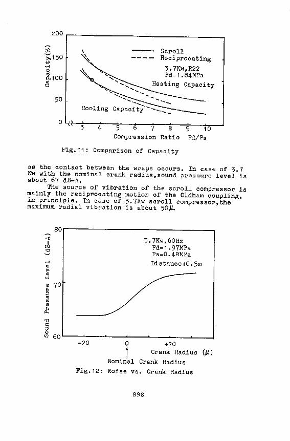
The remarkable feature of capacity is the less reduction at high compression ratio,as shown in Fig.11.
Comparing the capacity of the scroll compressor and the reciprocating comp~essor which has the same capacity at compression ratio 3.5,the scroll compressor can provide about 30% higher capacity at the condition of compression ratio B,in cooling and heating both. This is mainly due to the fact that there is no influence of reexpansion of discharge gas to suction process,in the scroll compressor. Therefore,the scroll compressor is
more applicable tQ heat pump systems whjch are faced with wide compression range.
NOISE AND VIBRATION
Noise level of the scroll compressor depends upon the amount of radial contact between the wraps,and the
accuracy of wrap machining. The relation between the noise level and the crank
radius is shown if Fig.12. Generally,noise increases
897
200 r-------------------------------------~ '*~150 ~ ·rl C) aj
0.100 aj
0
50
0
" ..... '-... ....
Scroll ---- Reciprocating
..... _
3.7Kw,R22 Pd=1. 84MPa
Capacity
Cooling Capaci t:;-----
3 4 5 7 8 9 10 Compression Ratio Pd/Ps
Fig.11: Comparison of Capacity
as the contact between the wraps occurs. In case of 3.7 Kw with the nominal cra.nk radius, sound pressure level is about 67 dB-A. The source of vibration of the scroll compressor is mainly the reciprocating motion of the Oldham coupling, in principle. In case of 3.7Kw scroll compressor,the maximum radial vibration is about 50#.
80 -<>: 3.7Kw,60Hz I lXI Pd=1. 97MPa 'd
Ps=0.48MPa rl Q) Distance:0.5m > Q)
....J
(!)
~ 70
~ II) II)
(!)
~ P..
'd J::: ~ 0 (I) 60
-20 0 +20
1 Crank Radius (/)) Nominal Crank Radius
Fig.12: Noise vs. Crank Radius
898

REL U.B ~L i TY
Compressor::~ instaJled :i.n the heat pump equi.pment, happen to be faced with msny difficult situetions,as well known.
Authors also :nvestigated the phenomena inhe~ently
occuring in the heat pump equipment,and came to know the compressors are needed to be tolerable to the various conditiona,as follows. For example,the internal elements of the compressor are washed away by the condensed refrigerant,which occurs after cycling transfering of refrigerant caused by the variation of ambient temperature, especially in air to air heat pump equipment. In such a condition,the compressor is forced to start up without oil film on the bearings. And there happens a stagnancy of circulating oil in the equipment,especially in the accumulator. And a lot of refrigerant migrates into the compressor,diluting oil and raising the density of oil in a moment.
Authors have designed the scroll compressor to be durable in the above conditions,by choosing the adequate material of bearings,by designing the suitable lublicating path,and by keeping the oil carry-over low.
CONCLUSION
'rhe features of' the 1ow side shell scroll compressor with sealing means we developed are as listed below;
1) The performance of the scroll compressor is higher than the most advanced reciprocating compressor,at present.
2) The cooling and heating capacities at high compression ratio are remarkably higher than those af the reciprocating compressor. (30% higher at compression ratio 8)
3) The scroll compressor is compact. (50% in number of parts,SO% in weight.60% in volume,comparing with the reciprocating nompressor)
4) The scroll compressor is ourable in the various operating conditions of heat. pump equipment.
RE:f<'ERENCES
1) Morishita, E. et al., "SCROLL COMPRESSOR ANALYTICAL MODEl,'', 19134 Purdue Compressor Conference.
2) Mc0ullough,J.E., 11 POSITIVE FLUIDE DISPLACEMENT APPARATUS11,U.s.P. 3,924,977,1975.
899

3) Young,N.0., 11 SCROLL-TYPE POSITIVE FLUID DISPLACEMENT APPARATUS 11 ,U.s.P. 3,884,599,1975.
4) Morishita,E. et al.,"SCROLL COMPRESSOR",Mitsubishi Denki Giho,vol.5B,No.5,May 1984.
5) Tojo,K. et al.,"A SCROLL COMPRESSOR FOR AIR CONDITIONERS",1984 Purdue Compressor Conference.
6) McCUllough,J.E.,"AXIAL COMPLIANCE MEANS WITH RADIAL SEALING FOR SCROLL-TYPE APPARATUS",U.S.P. 3,994,636, 1976.
900