a review on image processing techniques for damage
TRANSCRIPT
ICIC Express Letters ICIC International c⃝2021 ISSN 1881-803XVolume 15, Number 7, July 2021 pp. 779–790
A REVIEW ON IMAGE PROCESSING TECHNIQUES FOR DAMAGEDETECTION ON PHOTOVOLTAIC PANELS
Andi Najiah Nurul Afifah1, Indrabayu2, Ansar Suyuti1 and Syafaruddin1,∗
1Department of Electrical Engineering2Department of InformaticsUniversitas Hasanuddin
Jalan Poros Malino Km. 6, Gowa 92171, Indonesia∗Corresponding author: [email protected]
Received October 2020; accepted January 2021
Abstract. The image processing topics for damage detection on Photovoltaic (PV)panels have attracted researchers worldwide. Generally, damages or defects are detectedby using advanced testing equipment which is still quite varied according to the types ofdamages. In this respect, the types of damages of solar panels or photovoltaic modulescan be classified into damage on module surface, shadows and dirt from external effectsand internal problems originating from the PV system itself. These damages can be ef-fectively detected using the image processing method-based imaging technology, namelyElectroluminescence (EL) and Infrared (IR) thermal imaging. The results of measure-ment can be used for the application of complex computer vision techniques which aresorted into stages of image acquisition, image processing and pattern recognition. Thispaper would like to investigate more detailed about the damages of photovoltaic moduleidentification and the image processing techniques for the reasons of ensuring safe andefficient utilization of photovoltaic systems.Keywords: Image processing, Damages classification, Computer vision, Damages de-tection methods
1. Introduction. Nowadays, solar panels are one of the renewable energy sources widelyused. Solar panel, or also often called Photovoltaic (PV) system is a device that is ableto convert sunlight directly into electricity. Photovoltaic system can be referred to uti-lizing equipment to maximize the enormous potential of the energy of sunlight reachingthe earth. It has been widely implemented because of the relatively low cost and easymaintenance. It is quiet energy due to no moving parts and it is clean energy due tono liquid utilization. However, this panel cannot be protected from damage for instancescracking, failures of soldering and interconnection, potential material malfunction and hotspot problems. Therefore, early detection is highly important to ensure the continuousoutput energy supply of the PV panels.
Solar cells provide direct energy conversion from sunlight into electricity [1]. It ishighly necessary to enhance the output energy solar cell at high efficiency without anydefect problems during the implementation. Nowadays, it is very important to carry outinitial checks to detect damaged solar cells. It is due to the fact that early detection ofsolar cell damage is highly significant in the material research, manufacturing process andutilization of solar panels [2]. In other approach, the utilization of thermal energy bymeans of the photovoltaic-thermal systems has been investigated regarding the efficiencyenergy output enhancement of photovoltaic panels [3].
It is hard to determine the faulty of solar panel without expert knowledge. The faultdetection on solar panel has been proposed using drones, thermal cameras and RGB (Red,Blue, Green) cameras [4]. However, RGB images cannot provide sufficient information
DOI: 10.24507/icicel.15.07.779
779
780 A. N. N. AFIFAH, INDRABAYU, A. SUYUTI AND SYAFARUDDIN
and cannot detect damaged solar panels using only one type image. In this case, a thermalimage processing to detect solar panel failures which are caused by cracking, sticking withother objects and disconnecting the solar panel wire is more effectively instead of an RGBimage process.Damaging of PV cells can be caused by short-circuit condition of bypass diode [5].
In this case, it is highly important to reduce the impacts of unhealthy PV cells as theconsequence of surface deterioration, such as discontinuity output, cracks and shading ofPV cells [6]. The non-uniform sunlight intensity entering the panel surface yields shadingoperation and potential hot-spot problems which might be sequentially damaging theshaded cells [7].The over-current due to internal faults of PV panels commonly produces an over-heat
condition and defects to PV components [8]. The types of internal faults of PV panel areground and line to line faults. A ground fault condition is the current flowing to groundthrough the earthing system that provides pathway between one or more conductors ofarray. Meanwhile, the line to line fault is the short-circuit connection of two parts ofpanel with different voltage levels. Another type of dangerous fault in PV array is causedby low intensity of sunlight during evening condition.Different techniques of fault identification are concentrating on the framework design
of automatic diagnostic system for damage identification of solar panel components usingthermal image processing with accurate and timely response to alert the unsafe conditions[9]. This research detects accurately the hotspot from image using Simple Linear IterativeClustering (SLIC) of super-pixel technique. SLIC is based on a spatial localization of K-means clustering version which is a very good tool for decomposing an image into smallhomogeneous regions. This technique saves the efficiency, power production and overhaultime for the solar panels effectively.Some of the faulty PV modules are well-identified, such as failures in the Anti-Reflective
Coating (ARC), bubbles in the solar modules, and browning and yellowing of modules[10]. Failures in the ARC are due to an oxidation of the ARC components and might affectloss of adherence between PV cell materials. Furthermore, bubble inside the solar paneloccurs due to a chemical reaction where some gasses from PV cell materials are released.Other failures of browning and yellowing modules may reduce in the light transmittanceentering the solar cells and thus a decrease in the energy output.Analysis methods through images processing of solar cell performance are commonly by
scanning techniques of small parts of the solar cell in order to obtain spatial informationof damages. Combination of the image processing methods with more recently scanningmethods is highly necessary due to the complex interpretation and analysis of images,different material and process, varied test conditions and deviation from the actual per-formance of the solar cell [11]. Therefore, this paper attempts to provide clear informationregarding the photovoltaic damage detection based on computer vision for the reasons ofensuring safe and efficient use of solar systems.The contribution points of this study can be divided into academic and practical per-
spectives. From academic, it summarizes and provides a more detailed damage classifica-tion. Several points related to the causes of damage to solar panels were also discussedthat show a type of damage can be caused by several causes. The methods of imageprocessing for identifying the damage are also presented. These findings contribute newinformation that can be used for future research. For practical contribution, it givesgeneral information for the company and users of PV in order to improve the quality ofproduction, installation, maintenance and proper monitoring of the user.More detailed information regarding the photovoltaic damage detection and other as-
pects of computer vision is provided in the following section. In Section 2, the classificationof damages is given. Section 3 deals with the overview of EL imaging and IR imaging. In
ICIC EXPRESS LETTERS, VOL.15, NO.7, 2021 781
Section 4, the review of computer vision damage detection is presented. Finally, Section5 shows the conclusions of this review study.
2. Classification of Damages. Different knowledge and experience have been elabo-rated over the past decade to identify the potential defects during the operation of PVpanels. This section reviews the commonly reported damages problems including thedamages classification focusing on the improvement of manufacturing PV cell technolo-gies, safety and lifetime operation of installed PV system. The main damage classificationsin PV system are surface defects on the PV module, external shading and soiling, andinternal of PV system. A description of these classifications is presented in Table 1.
Table 1. Classification of damages on PV modules
Classification TypesCauses of damages
of damages of damagesInstallation/ Surrounding
ClimateChemical Unintentional
maintenance environment reaction connectionCracking O O
SurfaceDelamination O O
defectsDiscoloration O
Bubbles ODefects in ARC O
External Shading O Oproblems Soiling OInternal Ground faults O Oproblems Line-line faults O
2.1. Surface defects on the PV module. On the PV module, surface defects lead tohot cells formally named as hot spots. A hot spot is an area of a PV module that has avery high temperature that could damage a cell or any other element of the module. Areview of the types of damages on PV module surface is presented as follows.
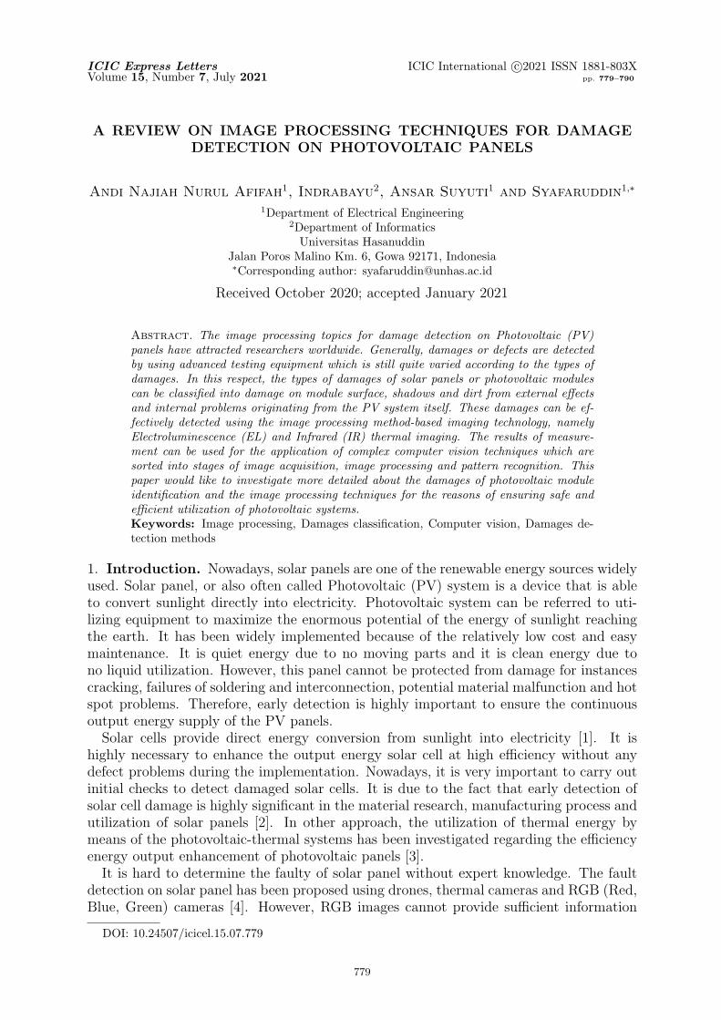
2.1.1. Cracking. Cracking as shown in Figure 1 is a usual problem occurring in PV arrayinstallation. The problem might change in different phases of the module utilization.Nevertheless, it occurs in majority of cases during installation, maintenance and mostlyduring the transportation of PV modules to installed location. Moreover, cracking isaffected by the rise temperature from the thermal stresses of cell and mechanical loadsdue to wind and snow (pressure and vibrations) [12]. In this respect, different colorlines can be noticed in the cell, although the cracks are not seen by bare eyes. It iscalled micro-cracks. Once PV panels with these varied color lines are scanned by the
Figure 1. Cracks in the cell [10]
782 A. N. N. AFIFAH, INDRABAYU, A. SUYUTI AND SYAFARUDDIN
Electroluminescence (EL), the tiny-crack spots are darker in EL due to lower generationof light emission. The crack isolates the healthy cell to produce normal electricity current[10].
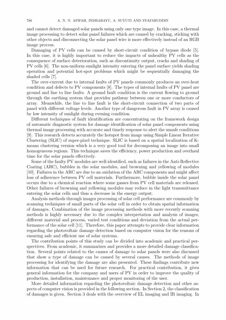
2.1.2. Delamination. Delamination is the damage of the binding between composing lay-ers of module lamination. This problem causes deficiency of heat dissipation and rises thepotential of reverse-bias cell heating. The main cause of delamination is the movementof cells out of the normal cell interconnection due to environmental stresses. Moreover,the operation of PV panel in surrounding high temperature environment accelerates theaging of physical cell materials that leads to delamination failures [12].Delamination highly potentially occurrs in hot and humid temperatures. If the problem
appears in the edge of panels, it will be more severe not only because of the power lossesbut it is dangerous due to potential electrical risks of panels and the area of installation.Figure 2 shows an image of the worse delamination that could damage the PV panelwhen the defect appeared. Delamination is also correlated with light transmittance lossentering the panel surface as materials do not respond optically coupled with the loss partof sunlight [10].
Figure 2. A PV module with delamination [10]
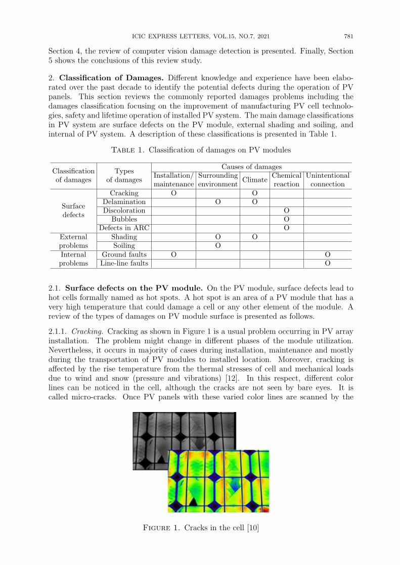
2.1.3. Discoloration. Discoloration (yellowing and browning) is a color changing in thePV cell materials from white to yellow and/or brown. It mainly occurs due to the re-duced performance of the Ethylene Vinyl Acetate (EVA) encapsulant. The main causes ofEVA performance reduction are Ultraviolet (UV) beams combined with water which hastemperatures higher than 50◦C. The color changes of the material produce a variation ofthe light transmittance entering the cells and result in decrease of energy production [12].Figure 3 presents an image of yellowing effect that occurs only over some parts of
PV panel. In some cases, yellowing appears in areas according to different polymericencapsulant of a different origin or characteristics. It means that yellowing occurs in
Figure 3. Discoloration of a PV module
ICIC EXPRESS LETTERS, VOL.15, NO.7, 2021 783
polymeric encapsulant instead of in the adherent element (usually EVA). In this respect,EVA does not uniformly exist in overall areas of the PV panel where different polymericencapsulant was utilized.
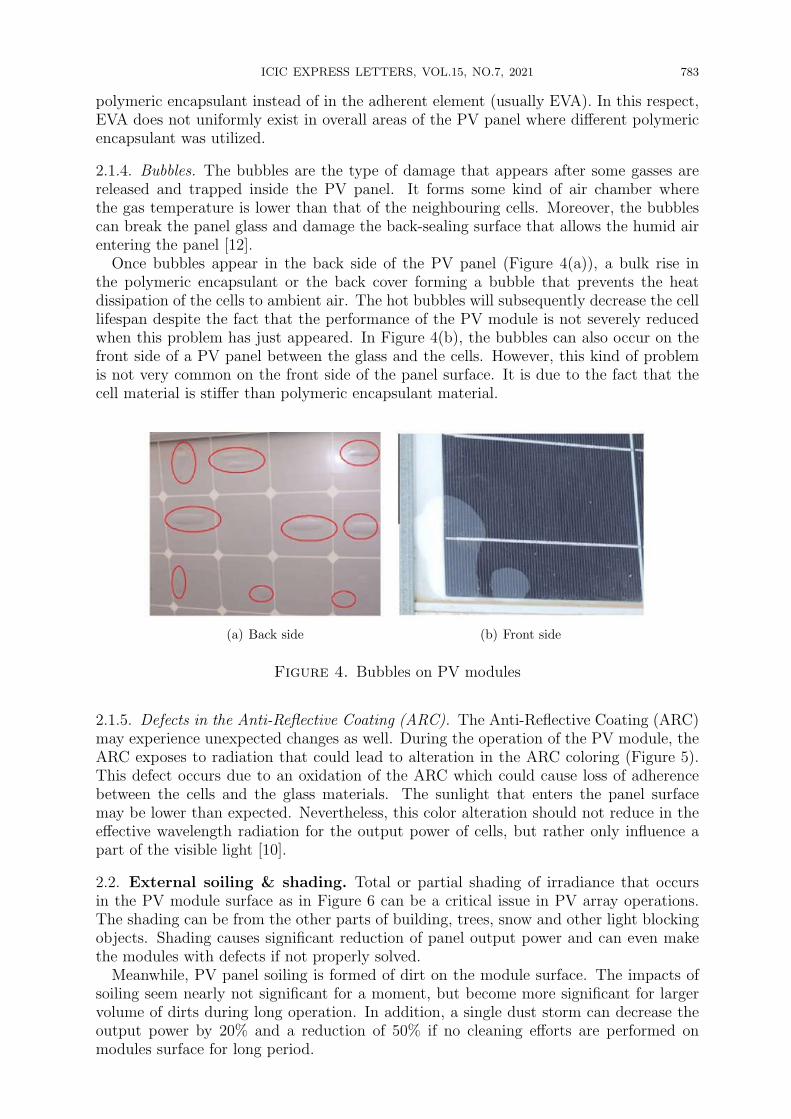
2.1.4. Bubbles. The bubbles are the type of damage that appears after some gasses arereleased and trapped inside the PV panel. It forms some kind of air chamber wherethe gas temperature is lower than that of the neighbouring cells. Moreover, the bubblescan break the panel glass and damage the back-sealing surface that allows the humid airentering the panel [12].
Once bubbles appear in the back side of the PV panel (Figure 4(a)), a bulk rise inthe polymeric encapsulant or the back cover forming a bubble that prevents the heatdissipation of the cells to ambient air. The hot bubbles will subsequently decrease the celllifespan despite the fact that the performance of the PV module is not severely reducedwhen this problem has just appeared. In Figure 4(b), the bubbles can also occur on thefront side of a PV panel between the glass and the cells. However, this kind of problemis not very common on the front side of the panel surface. It is due to the fact that thecell material is stiffer than polymeric encapsulant material.
(a) Back side (b) Front side
Figure 4. Bubbles on PV modules
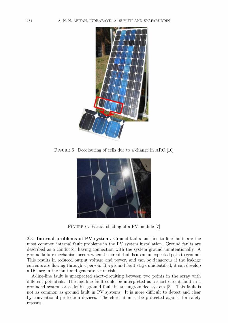
2.1.5. Defects in the Anti-Reflective Coating (ARC). The Anti-Reflective Coating (ARC)may experience unexpected changes as well. During the operation of the PV module, theARC exposes to radiation that could lead to alteration in the ARC coloring (Figure 5).This defect occurs due to an oxidation of the ARC which could cause loss of adherencebetween the cells and the glass materials. The sunlight that enters the panel surfacemay be lower than expected. Nevertheless, this color alteration should not reduce in theeffective wavelength radiation for the output power of cells, but rather only influence apart of the visible light [10].
2.2. External soiling & shading. Total or partial shading of irradiance that occursin the PV module surface as in Figure 6 can be a critical issue in PV array operations.The shading can be from the other parts of building, trees, snow and other light blockingobjects. Shading causes significant reduction of panel output power and can even makethe modules with defects if not properly solved.
Meanwhile, PV panel soiling is formed of dirt on the module surface. The impacts ofsoiling seem nearly not significant for a moment, but become more significant for largervolume of dirts during long operation. In addition, a single dust storm can decrease theoutput power by 20% and a reduction of 50% if no cleaning efforts are performed onmodules surface for long period.
784 A. N. N. AFIFAH, INDRABAYU, A. SUYUTI AND SYAFARUDDIN
Figure 5. Decolouring of cells due to a change in ARC [10]
Figure 6. Partial shading of a PV module [7]
2.3. Internal problems of PV system. Ground faults and line to line faults are themost common internal fault problems in the PV system installation. Ground faults aredescribed as a conductor having connection with the system ground unintentionally. Aground failure mechanism occurs when the circuit builds up an unexpected path to ground.This results in reduced output voltage and power, and can be dangerous if the leakagecurrents are flowing through a person. If a ground fault stays unidentified, it can developa DC arc in the fault and generate a fire risk.A-line-line fault is unexpected short-circuiting between two points in the array with
different potentials. The line-line fault could be interpreted as a short circuit fault in agrounded system or a double ground fault in an ungrounded system [8]. This fault isnot as common as ground fault in PV systems. It is more difficult to detect and clearby conventional protection devices. Therefore, it must be protected against for safetyreasons.
ICIC EXPRESS LETTERS, VOL.15, NO.7, 2021 785
3. Damage Detection Using Imaging Techniques. Quality control of the PV mod-ules is a requirement for good performance and long lifespan. PV modules may developdamage during operation, which can be fixed if they are discovered early [10]. Fast andreliable methods to evaluate the performance of the photovoltaic modules are required toconfirm the operation of the PV modules. Electroluminescence (EL) and Infrared ther-mal (IR) imaging inspections of PV are the solution to make sure the safety and greatperformance of the PV module. They are the imaging techniques, which recognize dam-age developing of PV modules [13]. The methods for damage detection of photovoltaicmodules are shown in Table 2.
Table 2. Methods for damage detection of photovoltaic modules
Common
process
Imaging technologies
Electroluminescence (EL) Infrared (IR) thermal
Image
acquisition
Sensovation digital camera SVSB-14-M [14]
FLIR C2 infrared camera [2], FLIRVue Pro [9]
Image
enhancement
Morphological smoothing process[18]
RGB to CIELAB colour space [2],RGB to grayscale [4, 17], Smooth-ing filter & edge-preserving [17]
Image
segmentation
Partitioned into individual solarcell subimages
RGB to HSV [17], K-means andSLIC [2]
Feature
extraction Independent Component Analysis
Distribution of graytones (intensitypixel) [19]
Damage
identification
(ICA) [18] Comparing mean values [4], Neuralnetwork classifier [20]
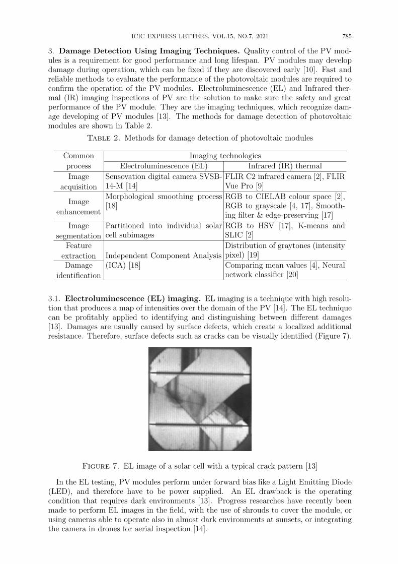
3.1. Electroluminescence (EL) imaging. EL imaging is a technique with high resolu-tion that produces a map of intensities over the domain of the PV [14]. The EL techniquecan be profitably applied to identifying and distinguishing between different damages[13]. Damages are usually caused by surface defects, which create a localized additionalresistance. Therefore, surface defects such as cracks can be visually identified (Figure 7).
Figure 7. EL image of a solar cell with a typical crack pattern [13]
In the EL testing, PV modules perform under forward bias like a Light Emitting Diode(LED), and therefore have to be power supplied. An EL drawback is the operatingcondition that requires dark environments [13]. Progress researches have recently beenmade to perform EL images in the field, with the use of shrouds to cover the module, orusing cameras able to operate also in almost dark environments at sunsets, or integratingthe camera in drones for aerial inspection [14].
786 A. N. N. AFIFAH, INDRABAYU, A. SUYUTI AND SYAFARUDDIN
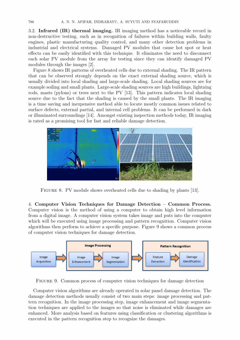
3.2. Infrared (IR) thermal imaging. IR imaging method has a noticeable record innon-destructive testing, such as in recognition of failures within building walls, faultyengines, plastic manufacturing quality control, and many other detection problems inindustrial and electrical systems. Damaged PV modules that cause hot spot or heateffects can be easily identified with this technique. It eliminates the need to disconnecteach solar PV module from the array for testing since they can identify damaged PVmodules through the images [2].Figure 8 shows IR patterns of overheated cells due to external shading. The IR pattern
that can be observed strongly depends on the exact external shading source, which isusually divided into local shading and large-scale shading. Local shading sources are forexample soiling and small plants. Large-scale shading sources are high buildings, lightningrods, masts (pylons) or trees next to the PV [13]. This pattern indicates local shadingsource due to the fact that the shading is caused by the small plants. The IR imagingis a time saving and inexpensive method able to locate mostly common issues related tosurface defects, external partial, and internal cell problems. It can be performed in darkor illuminated surroundings [14]. Amongst existing inspection methods today, IR imagingis rated as a promising tool for fast and reliable damage detection.
Figure 8. PV module shows overheated cells due to shading by plants [13].
4. Computer Vision Techniques for Damage Detection – Common Process.Computer vision is the method of using a computer to obtain high level informationfrom a digital image. A computer vision system takes image and puts into the computerwhich will be executed using image processing and pattern recognition. Computer visionalgorithms then perform to achieve a specific purpose. Figure 9 shows a common processof computer vision techniques for damage detection.
Figure 9. Common process of computer vision techniques for damage detection
Computer vision algorithms are already operated in solar panel damage detection. Thedamage detection methods usually consist of two main steps: image processing and pat-tern recognition. In the image processing step, image enhancement and image segmenta-tion techniques are applied to the images so that noise is eliminated while damages areenhanced. More analysis based on features using classification or clustering algorithms isexecuted in the pattern recognition step to recognize the damages.
ICIC EXPRESS LETTERS, VOL.15, NO.7, 2021 787
4.1. Image acquisition. The beginning step of every image processing is the imageacquisition. Basically, an image acquisition is a process through which images are takenfrom various devices. The common aim of image acquisition is to convert an opticalimage into an array of numerical data which could be later managed on a computer. Theoptical image is captured by suitable camera depending on needs and converted into amanageable form.
For IR imaging, there are many IR cameras existing on the market. In [2], FLIR C2infrared camera was operated for thermal imaging. It is a convenient infrared camera witha thermal sensitivity of < 0.10◦C and an infrared sensor resolution of 80×60. The distancebetween the camera and the PV module was set at 1 m. This camera takes images atangles between 20◦ to 35◦ to avoid casting shadows on the PV module. In [9], the IRcamera that is used is FLIR Vue Pro with resolution of 336× 256 pixels. This resolutionis quite high to display an appropriate thermal resolution from the panels. Another toolthat can be utilized for image acquisition is drone [4]. Drone takes solar panel arraypictures using RGB camera to recognize the position of solar panel and thermal camerato determine the error panel.
For EL imaging, images are captured with a Sensovation digital camera SVSB14-Munder forward bias with exposure time of 300 s [14]. A high resolution EL camera mightbe necessary in order to analyze the defect of a PV module. High resolution camera alsoenabled PV modules to be taken from a far distance and capturing more modules perimage [13]. When the images have been captured, then various processes are applied onthe images.
4.2. Image processing. There are two important stages of image processing, i.e., imageenhancement and image segmentation which will be explained as follows.
4.2.1. Image enhancement. Image enhancement is a pre-processing stage in image pro-cessing that aims to improve the quality of an image. In the process of image acquisition,image is often contaminated by external noise, resulting in degraded quality [15, 16].The goal of enhancement is an improvement of the image data that overcomes the exter-nal noise or unwilling misinterpretation and strengthens some image features for furtherprocessing.
For the IR images in [2], the RGB values were transformed to CIE L*a*b*. CIELABis a color space, stated by the International Commission on Illumination (Commissioninternationale de l’clairage). It has three coordinates to represent the lightness of the color,where L* = 0 yields black and L* = 100 is white, a* represent between red and green,where negative values indicate green and positive values indicate red, and b* representbetween yellow and blue where negative values indicate blue and positive values indicateyellow. The conversion from RGB to CIE L*a*b* decreases the computational complexityof the algorithm since the color scale was reduced from 3 to 2 dimensions. This minimizescomputation time and large variations of clusters.
Moreover, the proposed system in [4] converts the RGB to grayscale images to identifythe boundary of PV array. In [17], after converting RGB into gray scale, the imageis cropped to one selected panel, and removes noise by applying smoothing filter andedge-preserving. For the EL image, a particular morphological smoothing process isimplemented in order to smooth the dark-region background and preserve the defectshapes, before it is used for learning and detection [18].
4.2.2. Image segmentation. Image segmentation is an important step in image processingthat is used to find objects and boundaries. Image segmentation is a process of separatingforeground from the background or clustering regions of pixels according to similaritiesin shape or colour in order to identify and characterize the object. In [4], thresholdingmethod is applied to segmenting an image into a particle region, which consists of a
788 A. N. N. AFIFAH, INDRABAYU, A. SUYUTI AND SYAFARUDDIN
background region and objects under inspection based on the pixel intensities within theimage. This method produces the binary image. In [17], image segmentation is executedby converting image colour space from Red, Green and Blue (RGB) image into Hue,Saturation and Value (HSV) to split the colours and to enable the threshold mask todetect the hot-spot based on RGB to HSV conversion.In [2], image segmentation applies K-means clustering. K-means is used to classify
pixels that are in the same temperature range. Euclidean distance is used to group theimage data points to the nearest cluster index. After the image is divided into k groups, thehighest temperature range is selected. Finally, the isolated hotspot is presented includingthe average temperature value and relative percent area affected by the hotspot. Also in[9], the SLIC super-pixel technique is applied based on the spatial localization of the K-means clustering. SLIC is a good tool for decomposing an image into small homogeneousregions, that is to group pixels locally and thus to present a perceptual understanding ofcontent. Superpixel minimizes the complexity of the images from hundreds of thousandsof pixels to only a few hundred.
4.3. Pattern recognition. Pattern recognition can be explained as the distribution ofdata based on knowledge already gained or on statistical information extracted frompatterns and/or their representation. Pattern recognition is used to extract relevantfeatures from given image data and is used in computer vision for various applications.There are two major components for pattern recognition systems: feature extraction andclassification or identification for decision making.
4.3.1. Feature extraction. Feature extraction is the necessary step in pattern recognitionprocess to extract some features such as shape, texture, and color of the image data. Thesefeatures compose the significant information and can be used in multiple applications. In[19], features of images are extracted as they present a higher-order information of theimage and include description about the spatial distribution of gray tones. Accordingto the value of intensity points (pixels) in each combination, statistics are classified intofirst-order, second-order and higher-order statistics. Pixels whose values are very similarfor the objects are considered to be in the same group, while whose values are verydifferent for the objects are placed in different groups. In the proposed study of [20],features include a relatively small set of values that can be used to represent the targetin a feature space. For proposed panel recognition algorithm, lines are used as features.Although the appearance of a PV module is a continuous region that does not stand outfrom the background, its edges and the rectangular contour formed by the edges help toidentify the panel.
4.3.2. Damage identification. In this process, the parameter values that represent thecharacteristics of the object in each class are used as input data. The data is thenprocessed in order to obtain a formula to recognize the object. In the identification stage,generally two main processes are carried out, namely the training process and the testingprocess. The training process is done using a set of training data which contains featureparameters from feature extraction step that are used to differentiate between one objectand another. The algorithm used is selected based on the characteristics of the object.In [4], mean values of every solar cells were compared to identify higher or lower value
than the normal solar panel. If the faulty solar panel is found, then the red coloredbounding box will be drawn. For thermal image in [20], when the feature data is achieved,neural network classifier is used for generating the classification method. Scaled conjugategradient back propagation is adapted for regulating the bias and weights of the network.
ICIC EXPRESS LETTERS, VOL.15, NO.7, 2021 789
5. Conclusions.
5.1. Review results. A review of damage of photovoltaic and image processing tech-niques to identify the damage has been presented. There are various types of damage onphotovoltaic modules. The damage can be classified into categories based on the loca-tion of damages. From the review study in literature, it has been shown that the mostcauses of damage on PV are caused by surrounding environment, climate and chemicalreaction. In addition, the image processing is developed to be a promising technique fordetecting damage on photovoltaic panels. The technique provides fast, quite reliable andstraightforward interpretation results regarding to the condition of photovoltaic systems.
5.2. Future research tasks. Further interest and investigation of current research areinvited to develop a complete PV module condition monitoring technique, with imageprocessing and detection of the types of damages.
Acknowledgment. This research is granted by the National Ministry of Education andCulture of Indonesia under “Program Hibah PMDSU UNHAS-DIKTI” 2019-2021.
REFERENCES
[1] W. H. Piarah, Z. Djafar, Syafaruddin and Mustofa, The characterization of a spectrum splitterof techspec AOI 50.0mm square hot and cold mirrors using a halogen light for a photovoltaic-thermoelectric generator hybrid, Energies, vol.12, no.3, 2019.
[2] A. M. Salazar and E. Q. B. Macabebe, Hotspots detection in photovoltaic modules using infraredthermography, The 3rd Int. Conf. on Manufacturing and Industrial Technologies, 2016.
[3] Syafaruddin, Faharuddin, M. Adymulya and S. Latief, Application of photovoltaic-thermal (PV-T)power for cooling systems, ICIC Express Letters, Part B: Applications, vol.9, no.12, pp.1223-1231,2018.
[4] S. Lee, K. E. An, B. D. Jeon, K. Y. Cho, S. J. Lee and D. Seo, Detecting faulty solar panel basedon thermal image processing, IEEE Int. Conf. on Consumer Electronics (ICCE), 2018.
[5] Solmetric, Guide to Interpreting I-V Curves Measurements of PV Arrays, Application Note PVA-600-1, 2011.
[6] P. N. Botsaris and J. A. Tsanakas, Infrared thermography as an estimator technique of a photovoltaicmodule performance via operating temperature measurements, The 10th European Conf. on Non-Destructive Testing, 2010.
[7] H.-D. Yang, W. Xu, H. Wang and M. Narayanan, Investigation of reverse current for crystallinesilicon solar cells – New concept for a test standard about the reverse current, The 35th IEEEPhotovoltaic Specialists Conf. (PVSC), 2010.
[8] Y. Zhao, J. De Palma, J. Mosesian, R. Lyons and B. Lehman, Line-line fault analysis and protectionchallenges in solar photovoltaic arrays, IEEE Trans. Industrial Electronics, vol.60, no.9, pp.3784-3795, 2013.
[9] M. Alsafasfeh, I. Abdel-Qader and B. Bazuin, Fault detection in photovoltaic system using SLICand thermal images, The 8th Int. Conf. on Information Technology (ICIT), 2017.
[10] M. Munoz, M. Alonso-Garcıa, N. Vela and F. Chenlo, Early degradation of silicon PV modules andguaranty conditions, Solar Energy, vol.85, no.9, pp.2264-2274, 2011.
[11] S. Anwar, H. Efstathiadis and S. Qazi, Handbook of Research on Solar Energy Systems and Tech-nologies, IGI Global Publisher, USA, 2013.
[12] C. Abbas, A. Mounir and L. Sumanth, A review of photovoltaic DC systems prognostics and healthmanagement: Challenges and opportunities, Annual Conf. of the Prognostics and Health Manage-ment Society, 2016.
[13] U. Jahn and M. Herz, Review on Infrared and Electroluminescence Imaging for PV Field Application,Report of International Energy Agency Photovoltaic Power Systems (IEA-PVS) Programme, 2018.
[14] I. Berardone, J. L. Garcia and M. Paggi, Quantitative analysis of electroluminescence and infraredthermal images for aged monocrystalline silicon photovoltaic modules, IEEE the 44th PhotovoltaicSpecialist Conference (PVSC), 2017.
[15] J. Si, W. Sun and Y. Cheng, Image denoising using low rank matrix completion via bilinear gen-eralized approximate message passing, International Journal of Innovative Computing, Informationand Control, vol.16, no.5, pp.1547-1558, 2020.
790 A. N. N. AFIFAH, INDRABAYU, A. SUYUTI AND SYAFARUDDIN
[16] J. Zhang, H. Zhang, J. Zhang, X. Pen and X. Shi, Sparse reconstruction method based on starlettransform for high noise astronomical image denoising, International Journal of Innovative Comput-ing, Information and Control, vol.16, no.5, pp.1639-1654, 2020.
[17] M. Alajmi, K. Awedat, M. S. Aldeen and S. Alwagdani, IR thermal image analysis: An efficientalgorithm for accurate hot-spot fault detection and localization in solar photovoltaic systems, IEEEInt. Conf. on Electro Information Technology (EIT), 2019.
[18] D. M. Tsai, S. C. Wu and W. Y. Chiu, Defect detection in solar modules using ICA basis images,IEEE Trans. Industrial Informatics, vol.9, no.1, pp.122-131, 2013.
[19] V. S. B. Kurukuru, A. Haque, M. A. Khan and A. K. Tripathy, Fault classification for photovoltaicmodules using thermography and machine learning techniques, IEEE Int. Conf. on Computer andInformation Sciences (ICCIS), 2019.
[20] X. Gao, E. Munson, G. P. Abousleman and J. Si, Automatic solar panel recognition and defectdetection using infrared imaging, Proc. of SPIE 9476, Automatic Target Recognition, Baltimore,Maryland, United States, 2015.