a review of unidirectional ac-dc converter topologies for ... · a review of unidirectional ac-dc...
TRANSCRIPT
A Review of Unidirectional AC-DCConverter Topologies For Level-1Charging of Electric Vehicles
S.Harika1, Dr.R.Seyezhai2,Dr.A.Jawahar3, 1Research Scholar
2Associate Professor, 3Professor1,2,3Department of Electrical and Electronics Engineering
SSN College of EngineeringChennai, INDIA.
[email protected]@[email protected]
August 4, 2018
Abstract
AC-DC converter plays an essential role in charging ap-plication. This paper deals with review of different unidi-rectional ac-dc converter topologies for the level-1 charging.The performance of the proposed ac-dc converter topolo-gies are investigated and compared based on the parameterslike voltage gain, ripple content, switching loss, number ofswitch, number of diode and number of inductor. Fromthe analysis, the suitable converter topology is chosen forlevel-1 charging application. Overview of different unidi-rectional ac-dc converter topologies is highlighted. Further,the need of converter for charging application and use ofbattery charger for EV (Electric Vehicle) is described. Sim-ulation studies of the ac-dc converter topologies are carriedout in MATLAB/SIMULINK and the results are verified.
1
International Journal of Pure and Applied MathematicsVolume 120 No. 6 2018, 10853-10873ISSN: 1314-3395 (on-line version)url: http://www.acadpubl.eu/hub/Special Issue http://www.acadpubl.eu/hub/
10853
Keywords:Electric Vehicle (EV), unidirectional ac-dcconverter, Voltage gain, Efficiency, Ripple factor.
1 Introduction
Though, transportation systems are essential in todays human life,the concern is about intrinsic worth of mode of transport. It meansthat using of internal combustion engine (ICE) based vehicle hasmajor effects on global warming as it emits greenhouse gases, mak-ing air pollution and depletion of the earths petroleum resources.To overcome this, electric vehicle (EV) has emerged. Electrifyingthe vehicle is the most challenging and competitive solution. Thesurvey clears that for the same amount of energy, the range of EVis three times greater than gasoline powered vehicle and also it hasnumerous advantages like no gas requirement, zero emission, lowmaintenance, reduced noise pollution and cost effective. The useof renewable energy resources such as solar, wind etc for electricitygeneration made the electric vehicle easily accessible. It is safe todrive an EV car as in case of an accident, one can open up the airbag and cut the electricity supply from battery so that everyonecan be prevented from serious injuries. The Indian government hasannounced that by 2030 all the IC vehicles will be replaced by EVs[1] and India stands top ten positions in automotive market in theworld. For electric vehicle, battery charger plays a major role as itrequires frequent charging [2 &3] and it is essential to ensure thelife cycle of the battery and state of charge (SOC). On-board bat-tery charger is required to perform EV battery charging from gridwhich converts ac voltage into dc voltage and controls the chargingprocess [4].
The charging of battery is classified into three types : Level-1,Level-2 and Level- 3 chargers. Level -1 charger uses 120V whichis readily available in household outlets and transfer electricitythrough normal power cord and uses the basic equipment that themost EV’s come with. Level -2 charger uses 240V for enabling fastcharging of EV battery system but it requires an additional elec-tric vehicle service equipment (EVSE) and proper electric wiringcapable of handling high voltage. Level-3 provides DC fact charg-ing which chargers the battery in 20-30 minutes. Level-1 and Level
2
International Journal of Pure and Applied Mathematics Special Issue
10854
-2 provides AC electricity to battery through on- board chargerbut Level-3 charger bypass the on-board charger and provides theDC electricity directly to the battery via special charging port.The most commonly used charging ports are SAE and CHAdeMOchargers [5]. Though the Level-2 and Level-3 are fast charging,Level -1 is preferable because of• Low cost installation• Less expensive compared with other two chargers• No need of EVSE equipment• Less impact on electric utility peak demand chargesFor EV battery charging, converters are essential for charging andcontrolling process, converters of two types ac-dc converter anddc-dc converter [6]. With dc-dc converter, rectifier is required toconverter ac to dc which is uncontrolled output. And then dc-dcconverter converts and provides controlled output. As input currentshould be nearly sinusoidal, a small filter is required but to get dcoutput with low ripple, then large capacitor is placed which makesthe use of additional control scheme to get high frequency choppedsinusoidal shape of input current because it reflects as pulsed accurrent as input side [7]. This makes it as a tedious process. So,ac-dc converter bridgeless topology is preferable for battery charg-ing application [8]. Further, it is classified as unidirectional andbidirectional ac-dc converters. Unidirectional ac-dc converter al-lows power flow in one direction whereas bidirectional ac-dc con-verter allows power flow in two direction i.e., source to load andvice-versa. For the specification of level-1 charging, unidirectionalac-dc converter is chosen because it is less expensive and requiresless components compared to bidirectional ac-dc converter.[9-12].
Ac- dc converter suffers from power quality issues like injectionof current harmonics, flow of reactive power, losses in transmissionand distribution line [13 -15]. So, to improve the power quality,passive and active filters are used but it has the drawbacks of largesize, expensive and complex control makes the system too bulky.Thus the new type of converter called improved power quality uni-directional converters has been introduced to address the powerquality issues efficiently [16 - 17]. The converter design makes useof MOSFET as active switch since diode and thyristor has the de-merits of• Poor power quality
3
International Journal of Pure and Applied Mathematics Special Issue
10855
• Poor power factor• Voltage distortion• Rippled dc outputThis paper deals with the some of the six converter topologies.They are:A. Single Phase Unidirectional Buck ConverterB. Single Phase Unidirectional Converter with High Power FactorC. SEPIC ConverterD. Unidirectional Boost-Buck Converter for EV Battery ChargerE. Unidirectional Ac-Dc Converter with Coupled InductorF. Zero Voltage Source Hybrid Resonant PWM
2 UNIDIRECTIONAL AC-DC CON-
VERTER
A. Single Phase Unidirectional Buck Converter
The first topology deals with single- phase unidirectional buckconverter for power quality improvement. The control of buck con-verter is done in two ways: (i) Constant frequency control or pulsewidth modulation (ii) Variable frequency control or frequency mod-ulation control The operation is based on constant frequency inwhich the output is regulated through duty cycle, keeping frequencyas constant. Constant frequency operation is preferable instead ofvariable frequency because it reduces the filter size and controlsthe ripple content in dc output. The frequency is kept constantand the value of frequency is chosen in the range of few kHz tofew hundred kHz. Maximum power factor and maximum outputpower will be available and current is in phase with the voltage [18].The proposed circuit requires one active switch, five diode and oneinductor. The schematic circuit diagram of proposed single- phaseunidirectional buck converter is shown in Fig.1.
4
International Journal of Pure and Applied Mathematics Special Issue
10856

Fig.1. Single-phase unidirectional buck converter
Though it requires one active switch, the switching loss across theswitch is high which does not allow soft switching [19]. This topol-ogy fails to achieve the standard required for battery charging.Moreover, the buck converter is not suitable for charging appli-cation as it has low voltage gain and conversion ratio.
Fig.2 Input and Output Voltage of Single phase unidirectionalbuck converter
In Fig.2, the input voltage and output voltage of single phase uni-directional buck converter is depicted. The input voltage of 230Vis stepped down to 220V.B. Single Phase Unidirectional Converter With High PowerFactorIn unidirectional buck converter, passive filter is employed to getsinusoidal input current waveform, but it makes the circuit bulky,and with diode bridge rectifier, the power factor will be low andharmonic current will be injected to the source which makes thesystem unhealthy. So, current wave shaping technique is proposedin this topology to achieve unity power factor, controlled dc volt-age and fast dynamic response. The other topologies like neutralpoint clamped, flying capacitor and series connection of H-bridgerequires eight switches, four clamping diode and two flying capac-itor to meet the standard but PWM operation of proposed single-
5
International Journal of Pure and Applied Mathematics Special Issue
10857

phase unidirectional converter with high power factor requires onlyfour switches, two diodes and two capacitors. No clamping diodeand flying capacitor are required [20 & 21]. The schematic diagramof single- phase unidirectional converter with high power factor isshown in Fig.3.
Fig.3. Single phase unidirectional converter with high power factor
Based on the polarity of the input current, the switches will beturned on and turned off which leads to six operating states. Toanalyze the operating states, following assumptions are made:• the power switches are ideal• supply voltage is constant• dc capacitor voltages are equalThe principle of operation shows that high carrier frequency withthree-level voltage will be generated on rectifier leg a and with linefrequency two level voltage will be obtained on rectifier leg b. Thus,the output side of the ac source, five level voltage will be generated.During positive half cycle, diode D2 is turned on and the voltagelevel Vdc, Vdc/2 and 0 are generated. During negative half cycle,diode D1 is turned off and the voltage level 0, -Vdc, and -Vdc/2 aregenerated. The drawback of the topology is it requires four activeswitches and the switching loss across the single switch is about0.714W which makes the system unhealthy for charging application.The ripple content is high, the voltage gain and conversion ratio ishigh.
6
International Journal of Pure and Applied Mathematics Special Issue
10858
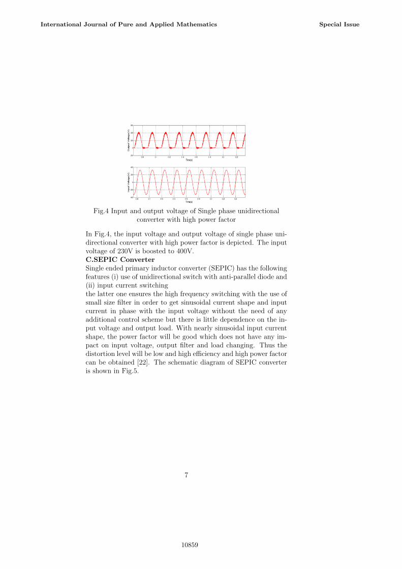
Fig.4 Input and output voltage of Single phase unidirectionalconverter with high power factor
In Fig.4, the input voltage and output voltage of single phase uni-directional converter with high power factor is depicted. The inputvoltage of 230V is boosted to 400V.C.SEPIC ConverterSingle ended primary inductor converter (SEPIC) has the followingfeatures (i) use of unidirectional switch with anti-parallel diode and(ii) input current switchingthe latter one ensures the high frequency switching with the use ofsmall size filter in order to get sinusoidal current shape and inputcurrent in phase with the input voltage without the need of anyadditional control scheme but there is little dependence on the in-put voltage and output load. With nearly sinusoidal input currentshape, the power factor will be good which does not have any im-pact on input voltage, output filter and load changing. Thus thedistortion level will be low and high efficiency and high power factorcan be obtained [22]. The schematic diagram of SEPIC converteris shown in Fig.5.
7
International Journal of Pure and Applied Mathematics Special Issue
10859
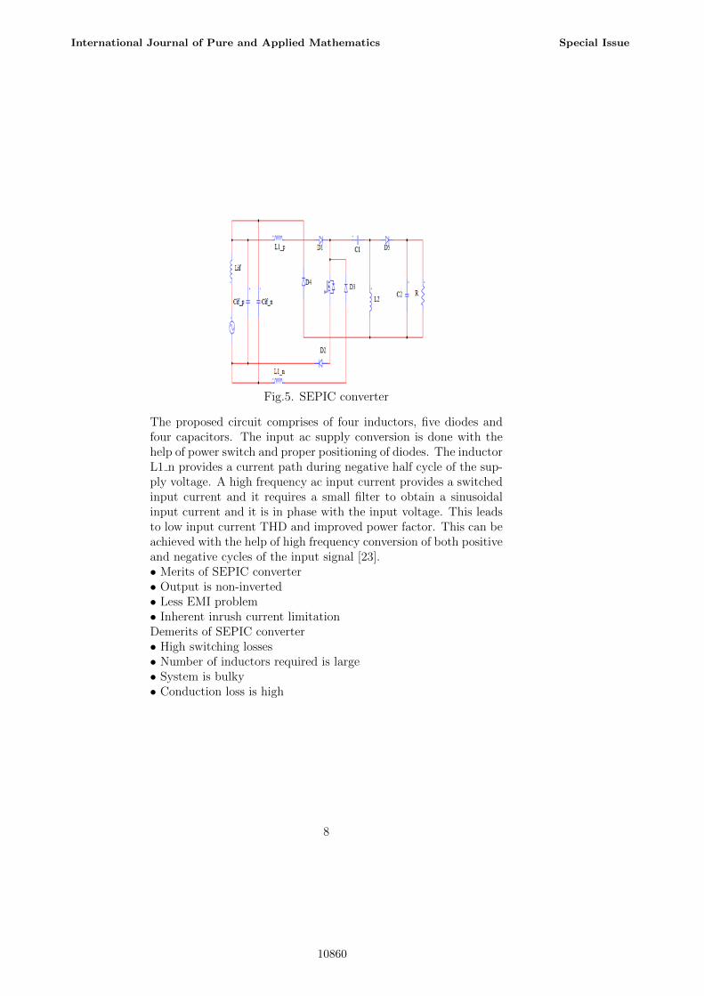
Fig.5. SEPIC converter
The proposed circuit comprises of four inductors, five diodes andfour capacitors. The input ac supply conversion is done with thehelp of power switch and proper positioning of diodes. The inductorL1 n provides a current path during negative half cycle of the sup-ply voltage. A high frequency ac input current provides a switchedinput current and it requires a small filter to obtain a sinusoidalinput current and it is in phase with the input voltage. This leadsto low input current THD and improved power factor. This can beachieved with the help of high frequency conversion of both positiveand negative cycles of the input signal [23].• Merits of SEPIC converter• Output is non-inverted• Less EMI problem• Inherent inrush current limitationDemerits of SEPIC converter• High switching losses• Number of inductors required is large• System is bulky• Conduction loss is high
8
International Journal of Pure and Applied Mathematics Special Issue
10860
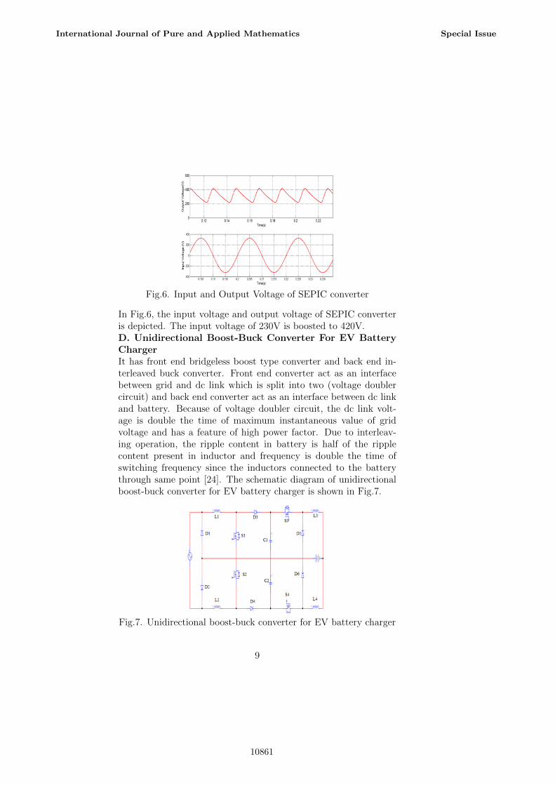
Fig.6. Input and Output Voltage of SEPIC converter
In Fig.6, the input voltage and output voltage of SEPIC converteris depicted. The input voltage of 230V is boosted to 420V.D. Unidirectional Boost-Buck Converter For EV BatteryChargerIt has front end bridgeless boost type converter and back end in-terleaved buck converter. Front end converter act as an interfacebetween grid and dc link which is split into two (voltage doublercircuit) and back end converter act as an interface between dc linkand battery. Because of voltage doubler circuit, the dc link volt-age is double the time of maximum instantaneous value of gridvoltage and has a feature of high power factor. Due to interleav-ing operation, the ripple content in battery is half of the ripplecontent present in inductor and frequency is double the time ofswitching frequency since the inductors connected to the batterythrough same point [24]. The schematic diagram of unidirectionalboost-buck converter for EV battery charger is shown in Fig.7.
Fig.7. Unidirectional boost-buck converter for EV battery charger
9
International Journal of Pure and Applied Mathematics Special Issue
10861
The front-end boost converter transfers energy from the power gridto the dc-link. As shown in Fig. 7, the front end converter consistsof two MOSFETs (S1 and S2), two inductive filters (L1 and L2),two diodes (D1 and D4) and split dc-link. The inductor L1 isconnected to positive of AC supply and inductor L2 is connected tothe negative of power supply and the middle point of input diodeand dc link is connected. During positive half cycle, MOSFET S1and diode D3 and D4 is used. During negative half cycle, MOSFETS2 and diode D4 and D1 is used.
The dc-dc back-end interleaved buck converter transfers energyfrom the dc-link to the batteries. As shown in Fig. 4, the backend dc-dc converter consists of two MOSFETs (S3 and S4), twoinductive filters (L3 and L4) and two diodes (D5 and D6). Theinductors are connected to the battery through the same point, andthe middle point of the dc-link is connecting to the middle pointof the output diodes D5 and D6. Though the ripple content is lowand power factor is high, the switching losses and voltage gain arenot upto the standard hence we are going for next topology [25].
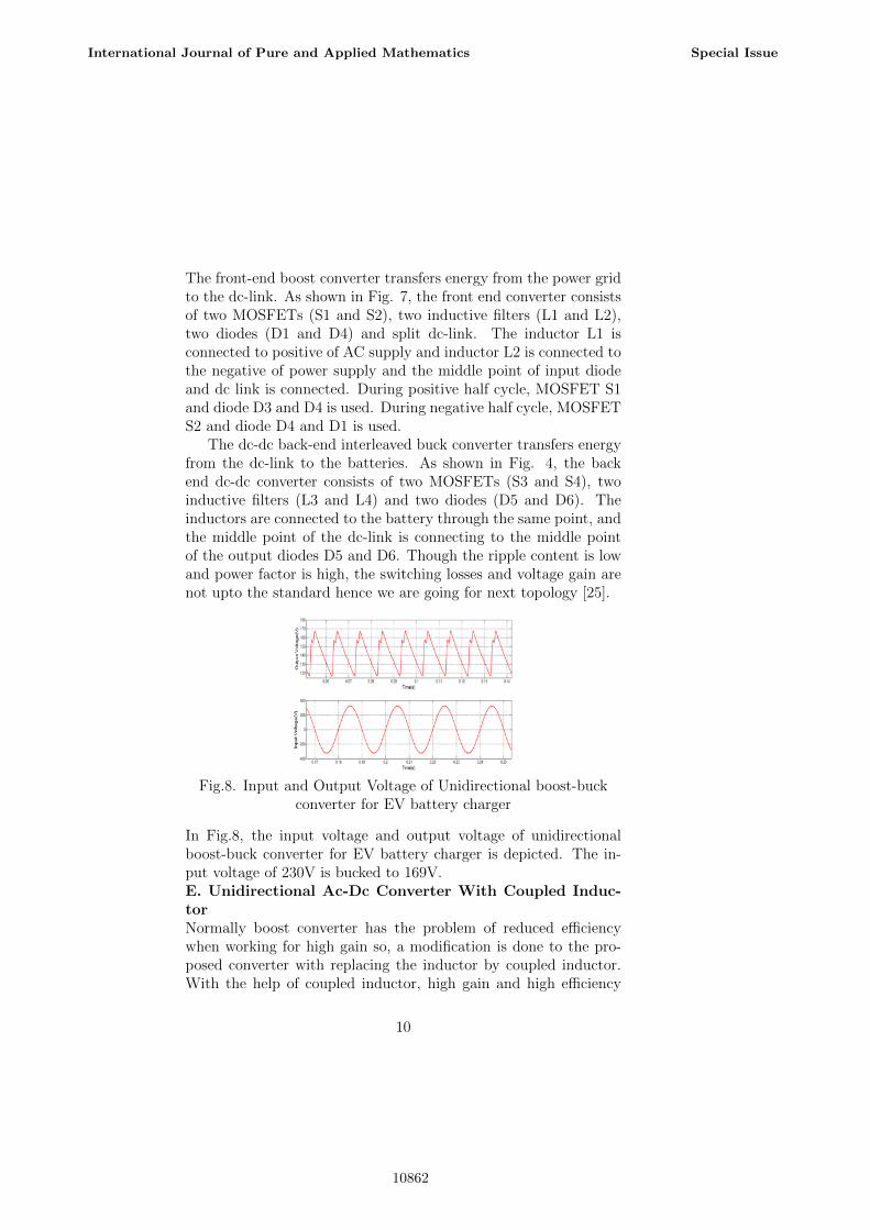
Fig.8. Input and Output Voltage of Unidirectional boost-buckconverter for EV battery charger
In Fig.8, the input voltage and output voltage of unidirectionalboost-buck converter for EV battery charger is depicted. The in-put voltage of 230V is bucked to 169V.E. Unidirectional Ac-Dc Converter With Coupled Induc-torNormally boost converter has the problem of reduced efficiencywhen working for high gain so, a modification is done to the pro-posed converter with replacing the inductor by coupled inductor.With the help of coupled inductor, high gain and high efficiency
10
International Journal of Pure and Applied Mathematics Special Issue
10862

can be achieved. Ac-dc converter suffers from harmonic injection,dc-link voltage ripple and to reduce that huge capacitor is neededwhich makes system bulky. Instead of using large capacitor, ultracapacitor is used in this topology, with this capacitor value is re-duced from 500 F to 10 F for single phase and 300 F to 10 F forthree phase [26]. The schematic diagram of unidirectional ac-dcconverter with coupled inductor is shown in Fig.9.
Fig.9. Unidirectional ac-dc converter with coupled inductor
During positive half cycle, switch S1 is operated and during neg-ative half cycle, switch S2 is operated. The input side inductor isused to get input current nearly sinusoidal waveform. With the helpof coupled inductor, the gain is increased but ripple content presentin the voltage is also increased. The dc link voltage is adjusted byadjusting the duty cycle. Here, ultra capacitor is used as auxiliaryenergy storage system. The power density of the converter dependsupon the ratio of power to volume [27].The uses of ultra capacitor are:• Regenerated power is stored in drive system• To meet transient power requirement of the system• Ultra capacitor with dc-link can be used as a buffer for rippleenergy of dc-link
11
International Journal of Pure and Applied Mathematics Special Issue
10863
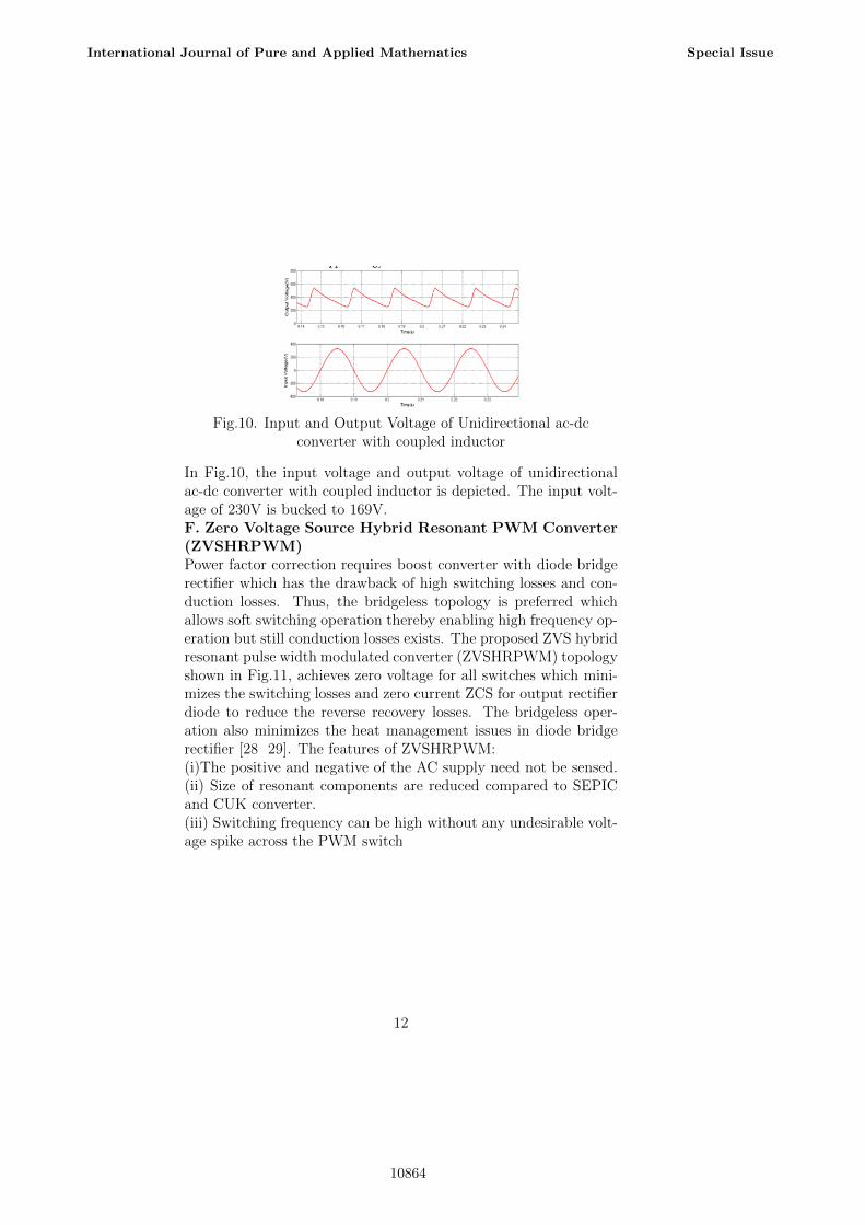
Fig.10. Input and Output Voltage of Unidirectional ac-dcconverter with coupled inductor
In Fig.10, the input voltage and output voltage of unidirectionalac-dc converter with coupled inductor is depicted. The input volt-age of 230V is bucked to 169V.F. Zero Voltage Source Hybrid Resonant PWM Converter(ZVSHRPWM)Power factor correction requires boost converter with diode bridgerectifier which has the drawback of high switching losses and con-duction losses. Thus, the bridgeless topology is preferred whichallows soft switching operation thereby enabling high frequency op-eration but still conduction losses exists. The proposed ZVS hybridresonant pulse width modulated converter (ZVSHRPWM) topologyshown in Fig.11, achieves zero voltage for all switches which mini-mizes the switching losses and zero current ZCS for output rectifierdiode to reduce the reverse recovery losses. The bridgeless oper-ation also minimizes the heat management issues in diode bridgerectifier [28 29]. The features of ZVSHRPWM:(i)The positive and negative of the AC supply need not be sensed.(ii) Size of resonant components are reduced compared to SEPICand CUK converter.(iii) Switching frequency can be high without any undesirable volt-age spike across the PWM switch
12
International Journal of Pure and Applied Mathematics Special Issue
10864
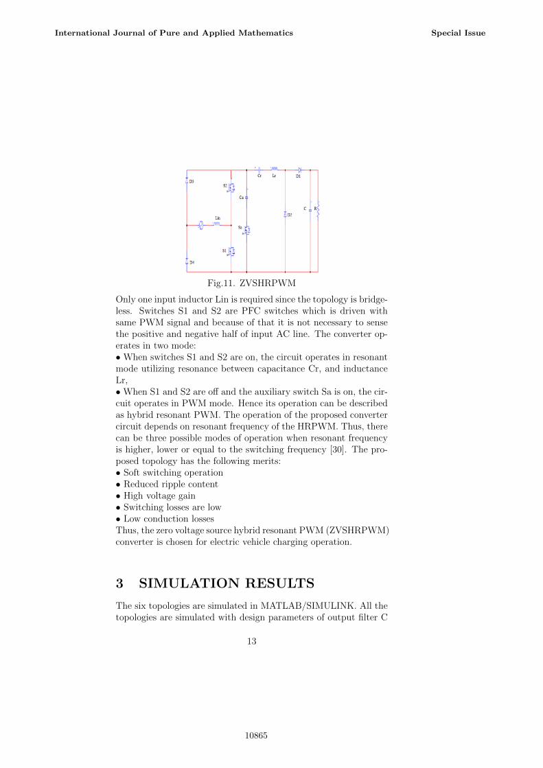
Fig.11. ZVSHRPWM
Only one input inductor Lin is required since the topology is bridge-less. Switches S1 and S2 are PFC switches which is driven withsame PWM signal and because of that it is not necessary to sensethe positive and negative half of input AC line. The converter op-erates in two mode:• When switches S1 and S2 are on, the circuit operates in resonantmode utilizing resonance between capacitance Cr, and inductanceLr,• When S1 and S2 are off and the auxiliary switch Sa is on, the cir-cuit operates in PWM mode. Hence its operation can be describedas hybrid resonant PWM. The operation of the proposed convertercircuit depends on resonant frequency of the HRPWM. Thus, therecan be three possible modes of operation when resonant frequencyis higher, lower or equal to the switching frequency [30]. The pro-posed topology has the following merits:• Soft switching operation• Reduced ripple content• High voltage gain• Switching losses are low• Low conduction lossesThus, the zero voltage source hybrid resonant PWM (ZVSHRPWM)converter is chosen for electric vehicle charging operation.
3 SIMULATION RESULTS
The six topologies are simulated in MATLAB/SIMULINK. All thetopologies are simulated with design parameters of output filter C
13
International Journal of Pure and Applied Mathematics Special Issue
10865
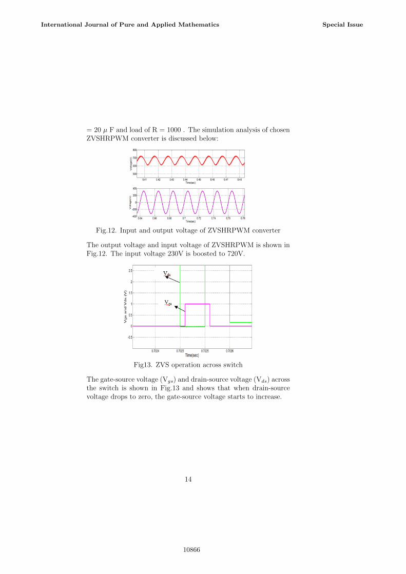
= 20 µ F and load of R = 1000 . The simulation analysis of chosenZVSHRPWM converter is discussed below:
Fig.12. Input and output voltage of ZVSHRPWM converter
The output voltage and input voltage of ZVSHRPWM is shown inFig.12. The input voltage 230V is boosted to 720V.
Fig13. ZVS operation across switch
The gate-source voltage (Vgs) and drain-source voltage (Vds) acrossthe switch is shown in Fig.13 and shows that when drain-sourcevoltage drops to zero, the gate-source voltage starts to increase.
14
International Journal of Pure and Applied Mathematics Special Issue
10866
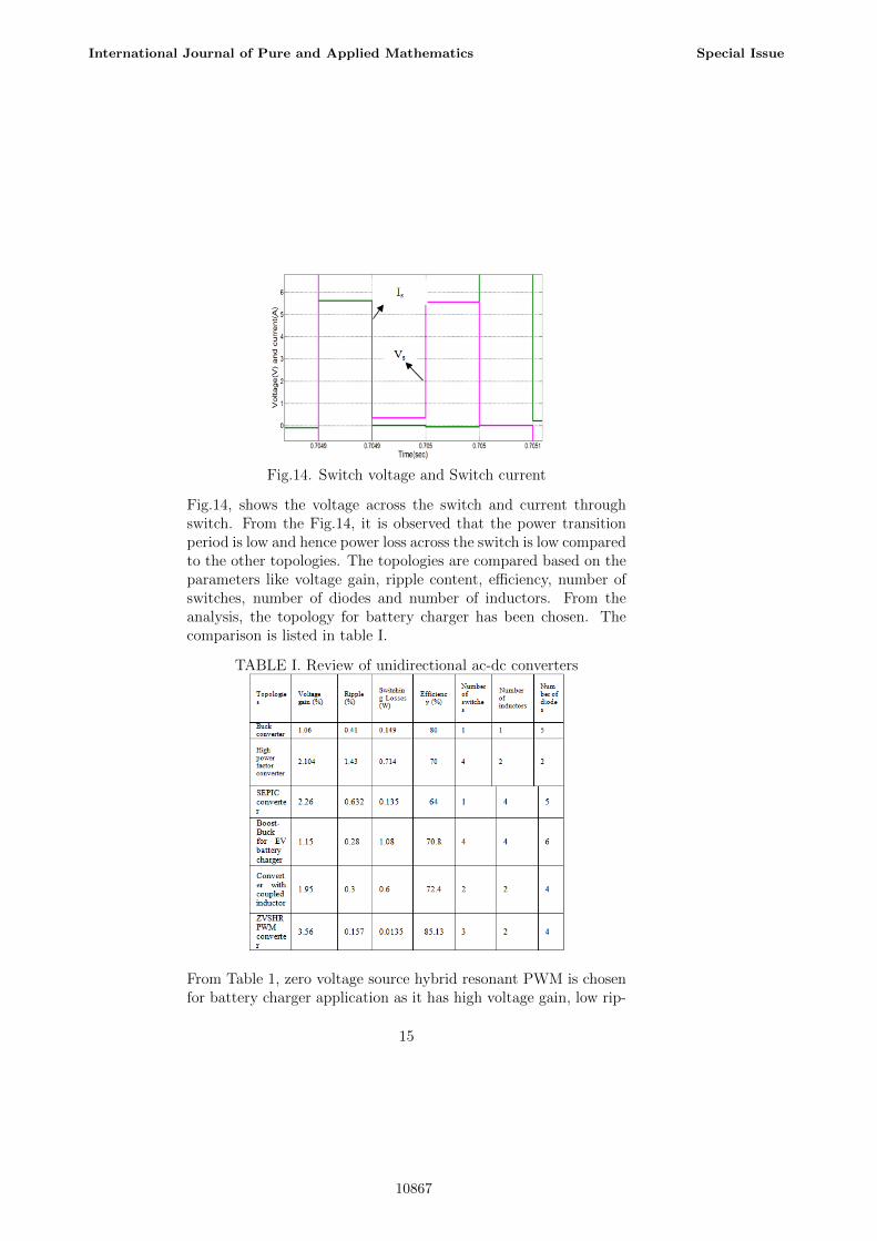
Fig.14. Switch voltage and Switch current
Fig.14, shows the voltage across the switch and current throughswitch. From the Fig.14, it is observed that the power transitionperiod is low and hence power loss across the switch is low comparedto the other topologies. The topologies are compared based on theparameters like voltage gain, ripple content, efficiency, number ofswitches, number of diodes and number of inductors. From theanalysis, the topology for battery charger has been chosen. Thecomparison is listed in table I.
TABLE I. Review of unidirectional ac-dc converters
From Table 1, zero voltage source hybrid resonant PWM is chosenfor battery charger application as it has high voltage gain, low rip-
15
International Journal of Pure and Applied Mathematics Special Issue
10867
ple content and low switching losses with low number of switches,diode and inductors. The proposed converter has 85.13 % efficiencyand also it enables the soft switching which allows high frequencyoperation. This topology reduces switching losses and conductionlosses by employing ZVS and ZCS. Thus, the ZVSHRPWM con-verter is suitable for battery charging application. The proposedtopology can also be used in plug-in hybrid vehicle(PHEV), resi-dential application and smart grid application
4 CONCLUSION
This paper has presented the various topologies of unidirectionalconverter for battery charging applications. These topologies aredesigned and simulated in MATLAB. From the results, it is ob-served that ZVS hybrid resonant PWM (ZVSHRPWM) results inhigh gain, high efficiency, reduced output voltage ripple, and lowswitching losses compared to the other topologies. Hence, the pro-posed AC-DC converter will be an appropriate topology for ElectricVehicles.
References
[1] K. Schneider, C. Gerkensmeyer, M. Kintner-Meyer and R.Fletcher, Impact assessment of plug-in hybrid vehicles on pa-cific northwest distribution systems in Proc. 2008 IEEE powerand energy society general meeting-conversion and delivery ofelectrical energy in the 21st century,pp. 1-6, 2008.
[2] . Mahdi Mansouri, S. Hr. Aghay Kaboli, Jeyraj Selvaraj, Nas-rudin Abd. Rahim, ”A Review of Single Phase Power FactorCorrection A.C.-D.C. Converters”, IEEE Conference on CleanEnergy and Technology (CEAT) , pp 389-394,2013.
[3] .Ehab Belal, Hassan Mostafa, M. Sameh Said, ”Comparisonbetween Active AC-DC Converters For Low Power EnergyHarvesting Systems”, 27th International Conference on Mi-croelectronics (ICM), pp 253-256,2015.
16
International Journal of Pure and Applied Mathematics Special Issue
10868
[4] Khushboo Arora, Sapna Katiyar, Rachit Patel,” Design andAnalysis of AC to DC Converters for Input Power Fac-tor Correction”, 2nd International Conference on Appliedand Theoretical Computing and Communication Technology(iCATccT), pp 171-176,2016.
[5] Nady Rocha; Andre Elias Lucena da Costa; Cursino BrandaoJacobina,” Parallel of two Unidirectional AC-DC-AC Three-Leg Converters to Improve Power Quality, IEEE Transactionson Power Electronics, pp 1-1,2017
[6] R. Suganya, S. Balamurugan,” Unidirectional ACDC PFCConverters for Power Quality Improvement”,InternationalJournal of Advanced Research in Electrical, Electronics andInstrumentation Engineering, Vol. 4, Issue 12, December 2015.
[7] D. Mallikarjuna Reddy, Y. V. Balarama Krishnarao, ”Unidi-rectional ACDC Boost Converters for Power Quality Improve-ment with BLDC Drive Based On Fuzzy Logic Controller”,International journal of Scientific Engineering and TechnologyResearch, Vol 4, issue. 50 , November 2016.
[8] Sung Min Park, ”Control and Integration Strategies for Bidi-rectional and Unidirectional Converters in Residential Dis-tributed Power Systems”, University of Connecticut, 2015.
[9] Jarno Alahuhtala and Heikki Tuusa, ” Space Vector Modulatedand Vector Controlled Three-Level Four-Wire UnidirectionalAC-DC-AC Converter”, 2nd IEEE International Conferenceon Power and Energy (PECon 08), , Johor Baharu, Malaysia,pp 781 - 786, December
[10] J. Alahuhtala, and H. Tuusa, ” Experimental Results of aThree-Level Four-Wire Unidirectional AC-DC-AC Converter”,The 2010 International Power Electronics Conference - ECCEASIA , pp 3080-3086,2010.
[11] Petar J. Grbovic, Alessandro Lidozzi, Luca Solero, and FabioCrescimbini, ”Five-Level Unidirectional T-Rectier for High-Speed Gen-Set Applications”,IEEE Transactions On
17
International Journal of Pure and Applied Mathematics Special Issue
10869
[12] Weimin Wu, Houqing Wang, Yuan Liu, Min Huang, andFrede Blaabjerg,” A Dual-BuckBoost AC/DC Converter forDC Nanogrid With Three Terminal Outputs”,IEEE Transac-tions On Industrial Electronics, Vol. 64, No. 1, January 2017.
[13] Nustenil S. M. L. Marinus; Cursino B. Jacobina; Nady Rocha;Reuben P. R. de Sousa.” Unidirectional single-phase AC-DC-AC three-level and two-level three-legconverters”,IEEE En-ergy Conversion Congress and Exposition (ECCE) , pp 2023-203,2017.
[14] Bhim Singh, Brij N. Singh, Ambrish Chandra, Kamal Al-Haddad, Ashish Pandey, and Dwarka P. Kothari, ”A Re-view of Single-Phase Improved Power Quality ACDC Convert-ers”,IEEE Transactions On Industrial Electronics, Vol. 50, No.5, October 2003.
[15] V.Jaikumar, Dr.G.Ravi, V.Vijayavelan and M.Kaliamoorthy,”An Improved High performance Three Phase Ac-Dc BoostConverter with Input Power factor Correction”, lET-UK Inter-national Conference on Information andCommunication Tech-nology in Electrical Sciences (ICTES 2007), Dr. MG.R. Uni-versity, Chennai, TamilNadu, India., pp. 221-228, Dec. 20-22,2007.
[16] .S.Arunraj, ”Novel Trends On Unidirectional AcDc Boost Con-verters Using Fuzzy Logics For Power Quality Mitigation”, In-ternational Journal On Engineering Technology and SciencesIJETS , Volume II, Issue X, October - 2015.
[17] Sunil Patnaik and Hitesh Lade,” Versatile Unidirectional Ac-Dc Converter With Harmonic Current And Reactive PowerCompensation For Smart Grid Applications”, InternationalResearch Journal of Engineering and Technology (IRJET) ,pp 2163 - 2170, Volume: 02 Issue: 04, July-2015.
[18] Muzaffar Hussain, Mubashir Ul Zaman, Shahid Iqbal andShabana Urooj,”Performance Investigation of a Single-PhaseUnidirectional Buck Convertor for Improved Power Quality”,InternationalConference on Computing for SustainableGlobalDevelopment(INDIACom), pp 302-304,2014.
18
International Journal of Pure and Applied Mathematics Special Issue
10870
[19] Amaral, A.M.R; Cardoso, A.J.M, Buck Converter SimulationTechnique based on the Fourier Transform”, Power Electronicsand Drive System, PEDS’07, 2007, 7th International Confer-ence on
[20] B.R. Lin and T.Y. Yang,” Single-phase unidirectional AC/DCconverter with high power factor”, IEE Proc.-Electr. PowerAppl., Vol. 152,Issue No. 2, pp 141-148, March 2005.
[21] Manias, S.: Novel full bridge semicontrolled switch mode rec-tier, IEE Proc. B, Electro. Power Appl, 138, (5), pp. 252256,1991.
[22] Mohammad Rubaiyat Tanvir Hossain, Amina Hasan Abedin,and M. A. Choudhury,” A Single Phase SEPIC AC-DC Con-verter with Improved Power Factor and Input Current THD”9th International Conference on Electrical and Computer En-gineering, pp 373-376, 20-22 December, 2016.
[23] B. Singh, B. N. Singh, A. Chandra, K. Al-Haddad, A. Pandey,and D. P. Kothari, A review of single-phase improved powerquality AC-DC converters, IEEE Transactions on IndustrialElectronics, vol. 50, no. 5, pp. 962 981, Oct. 2003.
[24] Vtor Monteiro, J. G. Pinto1, Bruno Exposto, Lus F. C. Mon-teiro, Carlos Couto1, Joo L. Afonso,”A Novel Concept of Uni-directional Bridgeless Combined Boost-Buck Converter for EVBattery Chargers”, IEEE 24th International Symposium onIndustrial Electronics (ISIE) pp 190-195,2015.
[25] Kaushik Rajashekara, Present Status and Future Trends inElectric Vehicle Propulsion Technologies, IEEE J. Emerg. Sel.Topics Power Electron., vol.1, no.1, pp.3-10, Mar. 2013.
[26] Shreelakshmi M P, Vivek Agarwal, ”Novel High Gain Topolo-gies for AC-DC Conversion with Power Factor Correctionand DC Link Capacitor Reduction”, IEEE International Con-ference on Power Electronics, Drives and Energy Systems(PEDES), pp 1-6,2016.
[27] J. W. Kolar, T. Friedli, and M. Hartmann, ”Three-phasePFC rectier and ac-ac converter systems-Part 1,Tutorial”, 26th
19
International Journal of Pure and Applied Mathematics Special Issue
10871
IEEE Applied Power Electronics Conference and ExpositionAPEC11,Mar 6-10,2011, Hawaii.
[28] Md. Muntasir Ul Alam, Wilson Eberle , Deepak Gautom; Fari-borz Musavi, ”A Soft- Switching Bridgeless AC-DC PowerFactor Correction Converter”,IEEE Applied Power ElectronicsConference and Exposition - APEC 2014, pp 103 -108, 2014.
[29] Yao, X. Ruan, X. Mao and Z. Ye, ”Reducing storage capacitorof a DCM boost PFC converter,” IEEE Trans. Power Electron.,vol. 27, no. 1, pp. 151-160, Jan. 2012.
[30] D. H. Kim, G. Y. Choe and B. K. Lee, DCM analysis and in-ductance design method of interleaved boost converters, IEEETrans. Power Electron.,vol.28,no.10,pp.4700-4711,Oct.2013.
20
International Journal of Pure and Applied Mathematics Special Issue
10872

10873

10874