a review of iron phosphate glasses and recommendations …
TRANSCRIPT

The INL is a U.S. Department of Energy National Laboratory operated by Battelle Energy Alliance
INL/EXT-13-30839Rev. 1
A Review of Iron Phosphate Glasses and Recommendations for Vitrifying Hanford Waste
Prepared for Idaho National Laboratory byDelbert E. Day and Chandra S. Ray Graduate Center for Materials Research Missouri University of Science and Technology
November 2013

DISCLAIMER
This information was prepared as an account of work sponsored by an agency of the U.S. Government. Neither the U.S. Government nor any agency thereof, nor any of their employees, makes any warranty, expressed or implied, or assumes any legal liability or responsibility for the accuracy, completeness, or usefulness, of any information, apparatus, product, or process disclosed, or represents that its use would not infringe privately owned rights. References herein to any specific commercial product, process, or service by trade name, trade mark, manufacturer, or otherwise, does not necessarily constitute or imply its endorsement, recommendation, or favoring by the U.S. Government or any agency thereof. The views and opinions of authors expressed herein do not necessarily state or reflect those of the U.S. Government or any agency thereof.

INL/EXT-13-3089 Rev. 1
A Review of Iron Phosphate Glasses and Recommendations for Vitrifying Hanford Waste
Delbert E. Day and Chandra S. Ray Graduate Center for Materials Research
Department of Materials Science and Engineering Missouri University of Science and Technology
Rolla, MO 65409
November 30, 2013
Idaho National Laboratory Idaho Falls, Idaho 83415
http://www.inl.gov
Prepared for the U.S. Department of Energy
Assistant Secretary for Environmental Management Under DOE Idaho Operations Office
Contract DE-AC07-05ID14517

iii
SUMMARY
This report contains a comprehensive review of the research conducted, world-wide, on iron phosphate glass over the past ~30 years. Special attention is devoted to those iron phosphate glass compositions which have been formulated for the purpose of vitrifying numerous types of nuclear waste, with special emphasis on the wastes stored in the underground tanks at Hanford WA. Data for the structural, chemical, and physical properties of iron phosphate waste forms are reviewed for the purpose of understanding their (a) outstanding chemical durability which meets all current DOE requirements, (b) high waste loadings which can exceed 40 wt% (up to 75 wt%) for several Hanford wastes, (c) low melting temperatures, can be as low as 900°C for certain wastes, and (d) high tolerance for “problem” waste components such as sulfates, halides, and heavy metals (chromium, actinides, noble metals, etc.). Several recommendations are given for actions that are necessary to smoothly integrate iron phosphate glass technology into the present waste treatment plans and vitrification facilities at Hanford.
The existing knowledge base for iron phosphate glasses, while limited by the small size of the melts produced to date, clearly demonstrates that there are no technical reasons why iron phosphate glass could not be used to vitrify high level and/or low activity waste at Hanford. To the contrary, there is considerable evidence showing that iron phosphate melts/glass are particularly well suited for many Hanford wastes that are high in sulfates (SO3), halides, chromium, etc., which severely limit the maximum waste loading possible in other oxide melts.
As an example, several studies have all concluded that the volume of Hanford LAW glass would be smaller if the LAW waste was vitrified in an iron phosphate glass. The only disagreement is on the magnitude of the reduction, but estimates range from 25 to 50% compared to the current WTP base line compositions and depending upon the assumptions used in the analysis. This reduction in volume is the result of the higher solubility of SO3 and halides in iron phosphate glass, which is roughly twice that for other oxide glasses, and the 10 to 15% higher density of iron phosphate glass waste forms. Other examples are cited herein for the Hanford HLW where the volume of vitrified HLW is estimated to be much smaller in an iron phosphate glass because of the high waste loadings, 40 to 75 wt% and the 10 to 15% higher density.
Compared to the waste at West Valley and the Savannah River Site, the wastes at Hanford are recognized as more challenging to process (vitrify), more variable in composition, and contain “problem” components that are expected to limit the waste form production rate. These factors suggest that iron phosphate glass, with its record of tolerance for compositional variations in a waste, should be useful and advantageous at Hanford. The documented characteristics of iron phosphate glass which recommend its use at Hanford are as follows:
1. Higher tolerance/solubility for sulfate (SO3), halides (F, Cl, I), heavy metals (Cr), etc. --- Smaller waste form volume.
2. Iron phosphate glass uses many of the components present in the waste, such as Fe2O3, P2O5, Al2O3, and Cr2O3, in a beneficial way that reduces the number/amount of glass forming chemicals (GFC) that must be added to the waste. Often, only one GFC is required, P2O5. --- Smaller waste form volume.

iv
3. Higher waste loadings that range from 40 to 75 wt% depending upon waste composition. --- Smaller waste form volume.
4. The planned pretreatment of LAW, to reduce Cs-137, and HLW, to remove/reduce aluminum, heavy metals (Cr) and sulfate, may not be necessary. A possibly better alternative could be to “blend” the waste. --- Save time/money.
5. Iron phosphate glass is robust and its ability to vitrify Hanford LAW at 1030°C in a research size JHCM modified with Inconel 693 electrodes has been demonstrated. --- Transition to larger scale.
The probability of unforeseen operational risks at Hanford is high, so having and “ace in the hole” is a good strategy in such circumstances. This opinion is reinforced in a recent National Research Council Report [NRC 2011], which stated, “No single waste form is suitable for all EM waste streams or suitable for all disposal environments. Consequently, DOE-EM would benefit from having a “toolbox” of waste forms suitable for different waste streams and disposal environments.”
It is suggested, therefore, that another tool be added to the toolbox at Hanford and that a small number of key experiments and activities be undertaken to insure that iron phosphate glass technology will be ready and available for that important role at Hanford when needed. These key experiments and activities should include: a) larger scale melting experiments in a pilot-plant scale (or larger) JHCM, b) formulating and evaluating optimized iron phosphate glass compositions directed at those Hanford waste streams that are considered to be the best targets of opportunity, i.e., offer the highest potential for accelerating the vitrification effort and reducing the cost, and c) developing an algorithm for predicting glass compositions from feed composition inputs that meet all melter and glass waste form requirements.

v
CONTENTS
SUMMARY ................................................................................................................................................. iii
ACRONYMS ............................................................................................................................................... xi
1. INTRODUCTION .............................................................................................................................. 1
2. VITRIFICATION CHARACTERISTICS AND STRUCTURAL FEATURES OF IRON PHOSPHATE GLASSES ................................................................................................................... 2
2.1 General ..................................................................................................................................... 2
2.2 Glass Formation Region ........................................................................................................... 2
2.3 Melting Iron Phosphate Glasses ............................................................................................... 3 2.3.1 Effect of Melting Temperature, Time, and Atmosphere on the Redox of Iron
Ions .............................................................................................................................. 4 2.3.2 Effect of Composition on the Redox of Iron Ions ....................................................... 7
2.4 Structural Features ................................................................................................................... 9
3. IRON PHOSPHATE GLASS WASTE FORMS: LABORATORY SCALE MELTS ................... 15
3.1 Waste Forms Containing ........................................................................................................ 16 3.1.1 Hanford HLW Sludges; C-106, B-110, C-112, T-111, and TFB .............................. 16 3.1.2 Hanford High Chromium HLW ................................................................................ 19 3.1.3 Hanford Low Activity Waste (LAW); Average LAW and AZ102 LAW ................ 19 3.1.4 INL Sodium Bearing Waste (SBW) .......................................................................... 21 3.1.5 Aluminum-Clad Spent Nuclear Fuel (SNF) .............................................................. 21 3.1.6 Re-processed Spent Nuclear Fuel ............................................................................. 22 3.1.7 Iron Phosphate Glass Waste Forms Containing Common and Important
Components Present in Nuclear Wastes ................................................................... 23
4. CONTINUOUS MELTING OF IRON PHOSPHATE GLASS ....................................................... 24
4.1 Joule Heated Research Scale Melter (RSM/JHCM) at PNNL ............................................... 24
4.2 Bench Scale Cold Crucible Induction Melter (CCIM) at KRI (Russia) and INL (USA) ..................................................................................................................................... 28 4.2.1 Bench Top CCIM Experiment at KRI ...................................................................... 29 4.2.2 Bench Scale CCIM Experiment at INL .................................................................... 30
5. SELECTED WASTE FORM PROPERTIES CRITICAL FOR NUCLEAR WASTE IMMOBILIZATION ........................................................................................................................ 31
5.1 Chemical Durability ............................................................................................................... 31 5.1.1 Product Consistency Test (PCT) and Vapor Hydration Test (VHT) ........................ 31 5.1.2 Chemical Durability Measured by Coupon Immersion Test (CIT) .......................... 35 5.1.3 Factors Controlling Chemical Durability .................................................................. 39
5.2 Density ................................................................................................................................... 40
6. PROPERTIES IMPORTANT TO MELT PROCESSING ............................................................... 41
6.1 High Temperature Viscosity .................................................................................................. 41
6.2 High Temperature Electrical Conductivity ............................................................................ 42
6.3 Corrosion of Refractory Ceramics ......................................................................................... 45

vi
6.4 Corrosion of Refractory Metals (Electrodes) ......................................................................... 47
6.5 Overview ................................................................................................................................ 50
7. FOCUS ON HANFORD WASTES ................................................................................................. 51
7.1 Overview ................................................................................................................................ 51
7.2 Hanford LAW ........................................................................................................................ 51
7.3 Hanford HLW ........................................................................................................................ 53
7.4 Direct Tank Hanford Waste ................................................................................................... 54
8. RECOMMENDATIONS FOR IMPLEMENTING IRON PHOSPHATE GLASS AT HANFORD ....................................................................................................................................... 55
9. CONCLUSIONS .............................................................................................................................. 57
10. ACKNOWLEDGEMENTS ............................................................................................................. 59
11. REFERENCES ................................................................................................................................. 60
FIGURES Figure 1. Composition (element in mol%) of phosphate-based glasses on the (Ca+Cs+
K+Li+Na+Pb)/P – (Al+Bi+Cr)/P – Fe/P ternary diagram [Pierce and Day, 2013]. ..................... 3
Figure 2. Concentration of Fe2+ ions, as measured by Mössbauer spectroscopy for iron phosphate glasses made by melting a 40 Fe2O3-60 P2O5, mol%, composition in air
at different temperatures (top axis) or melting at 1200oC for different times (bottom axis). Typical experimental error is denoted by the error bar [Ray et al. 1999a]. .................... 5
Figure 3. Change in the concentration of Fe2+ ions, measured by Mossbauer spectroscopy, for a
40 Fe2O3-60 P2O5 glass, mol%, melted at 1400oC for 1 h and then heated at
temperatures shown for 24 h. The decrease in Fe2+ concentration with increasing heat
treatment temperature indicates the oxidation of Fe2+ ions to Fe3+ ions (Ray et al. 1999a]. .......................................................................................................................................... 5
Figure 4. TGA in air for glasses prepared by melting a 40Fe2O3 - 60P2O5, mol%, composition at (A) 1400°C and (B) 1150°C for 1 h, and (C) TGA in nitrogen for the glass melted at 1400°C. A weight increase, which is attributed to the oxidation of
Fe2+ ions to Fe3+ ions, is evident when the samples are heated in air (curves A and B), but no weight gain is observed when these glasses are heated in nitrogen (curve C). ................................................................................................................................................. 6
Figure 5. Structure of Fe3(P2O7)2 showing the (Fe3O12)16- groups [Marasinghe et al. 1997, Ijjaali et
al. 1991, Malaman et al. 1992]. Numbered circles are oxygen ions and black circles are phosphorus ions. ......................................................................................................................... 10
Figure 6. Mossbauer spectra (at 295 K) for iron phosphate glasses, see Table II for composition [Marasinghe et al. 2000a]. .......................................................................................................... 13

vii
Figure 7. O1s X-ray photoelectron spectra for iron phosphate glasses, see Table II for composition [Marasinghe et al. 2000a]. ...................................................................................... 13
Figure 8. Raman spectra for iron phosphate glasses, see Table 2 for composition [Marasinghe et al. 2000a]. ................................................................................................................................... 14
Figure 9. Concentration of SO3 as a function of iron redox for the MS26AZ102F-2 glasses prepared at RSM (JHCM)-PNNL under different melting conditions [Sevigny et al. 2011, Day et al. 2012] ................................................................................................................. 28
Figure 10. Normalized sodium release, determined by the Product Consistency Test (PCT), from glassy (QG) or heat treated/partially crystallized(CCC)ironphosphate waste forms. Refs are Hanford LAW [Kim CW et al. 2003b], Hanford High Chromium HLW [Huang et al. 2004b], and Han Hanford TFB [Kim CW et al. 2003a]. Right hand bars denote DOE limit for LAW and HLW. ..................................................................... 32
Figure 11. Corrosion rate as determined by the Vapor Hydration Test (VHT), for two Hanford HLW glass (quenched) and heat treated (CCC)/partially crystallized iron phosphate waste forms and INL SBW glassy waste form. Waste loadings and references are the same in Figure 10. ....................................................................................................................... 32
Figure 12. Comparison of the normalized elemental mass release (g/m2) from a conventionally melted iron phosphate waste form (IPG40WG) and a CCIM melted waste form containing 40 wt% of the INL sodium bearing waste after PCT in DIW at
90oC for seven days. The environmental assessment (EA) glass is shown for
comparison. Elements for which the mass release was <0.01 g/m2 are not shown. Sodium is the only element in common for all three glasses. The initial (pHi) and final (pHf) pH of the leachate is given for each glass. Si in CCIM melted sample (*) is from the sacrificial SiC used in the CCIM and (**) is the DOE requirement for HLW [Kim et al. 2003a]. ............................................................................................................ 33
Figure 13. Dissolution rate (DR) in DIW at 90°C as a function of immersion time for the iron phosphate glass waste forms containing 40 wt% SBW prepared using conventional melting (IP40WG) and CCIM procedures (IPWG40-CCIM), and the reference EA glass. Initial pH of DIW was 5.8. The nearly constant pH of the leachate for the IP40WG and IP40WG-CCIM samples compared to that for the EA glass attributed to the larger buffering action of the phosphate glasses. .............................................................. 34
Figure 14. Normalized mass release for Na and Si for iron phosphate waste forms containing 26 wt% of simulated Hanford AZ102, LAW. RSM denotes slurry waste melted in PNNL research size joule heated melter [Sevigny et al. 2011], CCIM denotes slurry waste melted in cold crucible induction melter at INL [Soelberg and Rossberg 2011], Trial denotes dry simulated waste while Slurry denotes wet simulated waste (both melted in electric furnace at MO-SCI Corp, Rolla MO). Starter denotes the glass frit made from the MS26AZ102F-2 composition that was conventionally melted at MO-SCI Corp and used as a startup glass at the beginning of the RSM/JHCM experiment at PNNL [Sevigny et al. 2011] and CCIM experiment at INL [Soelberg and Rossberg 2011]. .......................................................................................................................... 35
Figure 15. Iron phosphate glass containing TFB waste. Variation of the dissolution rate of iron phosphate waste forms in deionized water with their O/P molar ratio. The glasses contained 19-38 Fe2O3, 42-63 P2O5, 3-22 Na2O, and 1-9 wt% others [Day et al. 1998]. ........................................................................................................................ 36

viii
Figure 16. Dissolution rate at 90oC as a function of O/P molar ratio for iron phosphate glasses containing INL sodium bearing waste (SBW, numbers denotes wt% SBW in the waste form) in comparison to other iron phosphate waste forms. Data for iron phosphate glass containing (20 to 40 wt%) Hanford TFB waste (squares) [Marasinghe et al. 1998]. NKFP and NCFP [Kim et al. 2003c] which contain (20 mol% sodium (N)/potassia (K), 20 to 32 mol% Fe2O3 and 48 to 60 mol% P2O5), F40M [Marasinghe et al. 1998] (contains 40 wt% Fe2O3 and 60 wt% P2O5) and FCs17 [Yu et al. 1997] which contains 29 wt% Fe2O3, 38 wt% P2O5, and 33 wt% Cs2O. Shaded area denotes general trend in dissolution rate with O/P ratio reported by [Marasinghe et al.
1998, Kim et al. 2003c]. Window glass dissolution rate is 10-7 to 10-8 g/cm2/min [Leerssen 2002]. ......................................................................................................................... 38
Figure 17. Log dissolution rate, DR, for iron phosphate glassy waste forms in DI water at 90oC for 7 days [Mesko et al. 1999] versus the number of Fe-O-P and Al-O-P bonds as calculated from the batch composition. Open squares are for glasses which contain 15 wt% SNF [Mesko et al. 1999], black dots denote sodium containing iron phosphate glass [Yu et al. 1997], black squares denote potassium aluminophosphate glasses [Peng and Day 1991], and black stars denote potassium alumino-iron phosphate glasses [Peng and Day 1991]. .................................................................................... 39
Figure 18. High temperature viscosity for an iron phosphate melt (MS26AZ102F-2) containing 26 wt% of a Hanford high sodium, high sulfate LAW measured with a rotating spindle viscometer [Day et al. 2012]. Data points are the average of three measurements. ............................................................................................................................ 42
Figure 19. High temperature AC conductivity, measured at Vitreous State Lab, Catholic University of America. Melt contained 26 wt% of the high sodium, high sulfate, Hanford LAW AZ102 [Day et al. 2012]. .................................................................................... 43
Figure 20. Electrical conductivity of iron phosphate melts containing Hanford LAW (MS LAW 1-1) and INL sodium bearing waste (SBW) [Vienna et al. 2002]. ............................................. 44
Figure 21. A deliberately cut vertical cross section of a high purity silica crucible after melting
~20 kgs of iron phosphate glass at 1150oC for 14 days. Melt contained 27 wt% of Hanford LAW and 20.3 wt% Na2O [Kim et al. 2003b]. .......................................................... 46
Figure 22. Corrosion rate, measured at the melt line, for three commercially produced refractories (cylindrical rods) rotated at 9.2 rpm for 24 h in an iron phosphate melt at the temperature shown. The F43 melt is 43Fe2O3 – 57P2O5 wt%. The T111, and C112 iron phosphate melts contain 35 and 50 wt% of simulated waste from Hanford tanks T111 and C112, respectively. The TFB iron phosphate melt contains 30 wt% of Hanford waste from Tank Farm B, average composition. DWPF is a borosilicate melt containing 28 wt% of a simulated waste, Savannah River [Chen and Day 1999]. ............ 47
Figure 23. Percent weight loss for Inconel 690 and 693 coupons (14x9x7 mm) submerged
in an iron phosphate melt at 1050oC and containing 30 wt% of Hanford LAW. Estimated error corresponds to the size of the data points [Zhu et al. 2005]. ............................. 48
Figure 24. Appearance of the front and back face of an Inconel 693 electrode after being used for
10 days at 1030oC in the small research scale joule heated melter to produce 124 kgs of an iron phosphate waste form containing 26 wt% of Hanford AZ102 LAW

ix
[Sevigny et al. 2011]. The average/maximum electrode current density was 1.6 and 3.5
A/cm2, respectively. ................................................................................................................... 49
Figure 25. Calculated amount metric tons) of iron phosphate glass waste form (281,000 MT) needed to vitrify Hanford LAW with no sulfate limit compared with the amount (718,000 MT) needed when the sulfate content of the batch is limited to 0.48 wt% and 448,000 MT for Rev. 4 baseline [Agnew et al. 2010]..................................................... 52
Figure 26. Grouping all of the high level wastes (HLW) at Hanford [Vienna and Marra 2012]. ............. 53
TABLES
Table I: Fraction of Fe2+ ions in a 40Fe2O3-60P2O5, mol%, glass when melted in different atmospheres at 1200°C for 2 h [Marasinghe et al. 1998]. ............................................................. 7
Table II: Fraction of ferrous ions as measured by Mössbauer spectroscopy, and O/P and Fe/P molar ratios in selected iron phosphate glass waste forms [Marasinghe et al. 1998, 1999]. ............................................................................................................................................ 8
Table III: Structural Data for Iron Phosphate Glasses Containing Na2O ................................................... 12
Table IV: Chemically durable iron phosphate glass waste forms containing various types of nuclear wastes. ............................................................................................................................ 17
Table V: Simplified composition (wt%) of the simulated wastes vitrified in iron phosphate glass waste forms in Table IV. ............................................................................................................ 18
Table VI: Data for selected iron phosphate waste forms containing components commonly present in nuclear waste. ............................................................................................................. 25
Table VII. Selected properties of iron phosphate glass waste forms containing 40 wt% SBW and prepared by conventional melting (IP40WG) and CCIM processing (IP40WG-CCIM) [Kim CW et al. 2003 (a, b), Gombert and Richardson 2001]. .................................................... 30
Table VIII. Average dissolution rate, DR, in deionized water at 90°C after 4, 8, and 16 days for glasses made by melting a 40Fe2O3 - 60P2O5, mol%, composition at temperatures listed for 1 h. ............................................................................................................................... 36

x

xi
ACRONYMS
BO Bridging Oxygen
BS Borosilicate
CCC Canister Centerline Cooling
CEES Columbia Energy and Environmental Services
CCIM Cold Crucible Induction Melter
CUA Catholic University of America
DOE Department of Energy
DTA Differential Thermal Analysis
EDS Energy Dispersive X-ray Analysis
HLW High Level Waste
ICP-AES Inductively Coupled Plasma-Atomic Emission Spectroscopy
INL Idaho National Laboratory
JHCM Joule Heated Ceramic Melter
LAW Low Activity Waste
Missouri S&T Missouri University of Science & Technology
MO-SCI MO-SCI Corporation
NBO Non-Bridging Oxygen Ions
PCT Product Consistency Test
PNNL Pacific Northwest National Laboratory
RSM Research Scale Melter
SBW Sodium Bearing Wastes
SRNL Savannah River National Laboratory
SRS Savannah River Site
TDD Technology Development & Deployment Program
VHT Vapor Hydration Test
VSL Vitreous State Laboratory, Catholic University
WL Waste Loading
WTP Waste Treatment Plant
XRD X-ray Diffraction Analysis
XRF X-ray Fluorescence Spectroscopy

xii

1
A Review of Iron Phosphate Glasses and Recommendations for Vitrifying Hanford Waste
1. INTRODUCTION The general purpose of this report is to acquaint persons (engineers, scientists, policy makers,
stake holders, etc.), interested in the disposal of nuclear waste, with the properties and current status of iron phosphate glass. Iron phosphate glass has been used, on a laboratory scale, to vitrify numerous wastes located at Hanford WA, the Savannah River Site, and the Idaho National Laboratory (INL). This report contains (a) a general review of the research that has been conducted, world-wide, on iron phosphate glass compositions over the past ~35 years, (b) a summary description of their key properties which are important to waste vitrification, and (c) data for iron phosphate glass and glass-ceramic waste forms that contain many types of simulated high and low level nuclear wastes stored at Hanford and INL. The results for iron phosphate waste forms melted in a small scale joule heated ceramic melter (JHCM) and in a cold crucible induction melter (CCIM) are also described. Those nuclear wastes which are best suited for vitrification in iron phosphate glass are identified and recommendations are given for the actions needed to implement iron phosphate glass technology at Hanford and INL.
Nuclear waste is currently being immobilized by a process called vitrification. This consists of dissolving the waste in a high temperature melt which is cooled to form a chemically durable glass that will be placed in long-term storage [Ramsey et al. 2011, Bingham et al. 2011]. This process has been adopted internationally and is considered the best technology available at this time [Donald et al. 1997]. In the United States, this technology has been used to vitrify nuclear waste at West Valley, is currently being used to vitrify high level waste (HLW) at the Savannah River Site and is intended to be used to vitrify the HLW and low activity waste (LAW) at the Hanford site [Ramsey et al. 2001].
Because of their good chemical durability in aqueous liquids and a mature manufacturing knowledge base, borosilicate glass was chosen to vitrify nuclear wastes in the United States and elsewhere [IAEA 1992, Lambert and Kim 1994, Donald et al. 1997, Perez et al. 2001]. Borosilicate glass has performed well when the waste has a reasonably simple composition. However, as the complexity and diversity of the chemical compositions of the various nuclear wastes stored worldwide became better known, the need for alternative glass compositions became more apparent [NRC 2011, Sengupta 2012]. Many of the wastes at Hanford contain components, such as volatile species like sulfates, cesium, halides (F, Cl, and I) and technetium, oxides like CrO3 and P2O5, and heavy metals (Mo, Zr, Pu, Pd), that are either chemically incompatible (phase separation) or sparingly soluble in borosilicate glass [Vienna and Mara 2012]. These troublesome components typically limit the waste loading (WL), to an undesirably low level, which increases the waste form volume and, therefore, the overall time and cost of vitrification.
Phosphate glasses, while initially considered for waste vitrification, were thought to have an inferior chemical durability and a less mature manufacturing base, which made them a poor choice for waste immobilization [Donald et al. 1997]. However, high quality optical phosphate glasses have been commercially produced for more than a century. More recently, ~400 metric tons of chemically durable, phosphate laser glass has been produced on a commercial scale (continuous melting at 1000 to 1200oC) and is in use at the National Ignition Facility [Campbell et al. 2000].
Since a high chemical durability is a key requirement for waste forms containing nuclear waste, phosphate glass would seem, at first glance, to be a poor choice for vitrifying nuclear waste. However, adding alumina, and other similar (R2O3) oxides, especially iron oxide (Fe2O3), to a phosphate glass greatly improves its chemical durability. In addition, phosphate glasses generally melt at lower

2
temperatures (as low as 900oC) to form fluid melts, and they are good solvents for most heavy metals (Cr, Ag, Mo, rare earths, actinides, (U, Pd) and gases such as F, Cl, I, SO2, and SO3.
In the USA, adding lead and iron oxide to a phosphate glass [Sales and Boatner 1984, 1986, 1988, Boatner et al. 1994] was found to substantially improve the chemical durability to the levels required for waste vitrification. One of the most effective ways of increasing the chemical durability of a phosphate glass is to add iron oxide to the glass. As described later in this report, the chemical durability of iron phosphate waste forms containing from 25 up to 80% of many types of nuclear waste satisfy all current DOE chemical durability (PCT, VHT) requirements, either as a glass or as a glass-ceramic. The chemical durability of many iron phosphate glass compositions is exceptional, exceeding that of all other types of phosphate glasses and, in many cases, that of other common glasses known for their high chemical durability. The advantages of using an iron phosphate glass matrix for immobilizing high level nuclear wastes are described in a recent excellent review [Sengupta 2012].
In addition to the USA and Russia, iron phosphate glass for waste vitrification has been studied in many other countries such as France, United Kingdom, Brazil, Japan, Korea, India, Germany, China, and Slovakia. Much of this work is described in the extensive list of references cited herein. At this time Russia is the only country using a phosphate glass, i.e., sodium alumino-phosphate containing ~1.5 wt% Fe2O3 [Mukhamet-Galeyev et al. 1995], on a large scale to vitrify nuclear waste. Some 5700 metric tons of a HLW waste have been successfully vitrified in Russia as part of its waste vitrification program [Roach 2013].
The remainder of this report (1) describes what is known about iron phosphate waste forms in terms of waste loading, processing, and performance, (2) identifies those waste types which are considered the best candidates for vitrification in iron phosphate glass or glass-ceramics and the benefits gained, (3) compares JHCM and CCIM melters, and (4) provides recommendations for how iron phosphate glass technology could be utilized by DOE to vitrify LAW and HLW at Hanford.
2. VITRIFICATION CHARACTERISTICS AND STRUCTURAL FEATURES OF IRON PHOSPHATE GLASSES
2.1 General Iron phosphate glasses have been investigated since the late 1960’s [Hirayama et al. 1968]. There are
many studies of the atomic structure of these glasses since properties such as chemical durability melt viscosity, melting temperature, and crystallization tendency depend upon the structural units in the glass. As a condensed review, the basic structural group in a phosphate glass is a phosphorus ion surrounded by four oxygen ions in the form of a tetrahedron, a PO4 group. Depending upon the overall glass composition, the PO4 tetrahedra can be isolated; in which case the oxygen/phosphorus (O/P) ratio is 4 and the material is referred to as an orthophosphate. An example would be FePO4. When two PO4
tetrahedra join together to form P2O7 groups, the O/P ratio is 3.5 and the material is referred as a pyrophosphate, Fe4(P2O7)2 being an example. When the PO4 tetrahedra join together to form chains of varying length or closed rings, the O/P ratio is 3 and the material is called a metaphosphate, an example being Fe(PO3)3. When the PO4 tetraheda join together to form a three dimensional network, then the O/P ratio is 2.5 as in P2O5. A phosphate glass, therefore, can be considered an inorganic polymer composed of PO4 monomers, dimers, trimers, etc., which are bonded together by other cations [Hoppe 1996].
2.2 Glass Formation Region Studies [Brow et al. 1994, Mogus-Milankovic et al. 1997] show that the region of glass formation for
binary Fe2O3-P2O5 compositions extends from about 15 to 45 mol% Fe2O3, the balance being P2O5. Compositions of lower Fe2O3 content also form glass, but they are not of practical interest since their chemical durability is poor. Binary glasses containing up to 75 mol% Fe2O3 have been reported [Vaughan

3
and Kinser 1975], but they tend to crystallize too rapidly to be of interest. The binary iron phosphate compositions that form glasses with the highest chemical durability and, therefore, be of most interest for waste vitrification, typically contain 30 to 40 mol% Fe2O3.
The source of iron and phosphorus does not seem to be of particular importance to glass formation since FePO4, Fe4(P2O7)3, Fe3O4, and Fe2O3, ammonium phosphate, P2O5, and phosphoric acid have all been used for preparing binary iron phosphate glasses [Yu and Day 1995, Yu et al. 1997]. The glass formation region is extended and in some cases glass formation becomes more probable as other components are added to make a ternary or quaternary iron phosphate glass. The properties and structure of a large number of ternary/quaternary iron phosphate glasses containing R2O oxides, (Na, K, Cs), RO oxides (Mg, Ca, Sr, Pb, Zn), R2O3 oxides (Al, Cr, Bi, In, Sc) and other oxides such as MoO3, U3O8, PuO2, ThO2, and HfO2 have been investigated as referenced elsewhere in this report, see Figure 1 [Pierce and Day 2013]. Section III describes numerous types of nuclear wastes that have been vitrified in iron phosphate glass, mainly on a laboratory scale.
Figure 1. Composition (element in mol%) of phosphate-based glasses on the (Ca+Cs+ K+Li+Na+Pb)/P – (Al+Bi+Cr)/P – Fe/P ternary diagram [Pierce and Day, 2013].
2.3 Melting Iron Phosphate Glasses As demonstrated by a large body of evidence, small quantities, ranging from 0.1 to 10 kg, of iron
phosphate glasses have been easily prepared in the laboratory by melting a homogeneous mixture, dry or wet, of the desired raw materials in commercially available refractory crucibles (dense silica, alumina or alumino-silicate) at temperatures between 900°C and 1350°C for times typically between 2 and 4 h For reasons that are not totally known, iron phosphate melts do not corrode these common refractory materials to any significant extent (as measured over a several day period), as do many iron-free phosphate glasses. Along with their outstanding chemical durability, this greatly reduced corrosion of common refractory oxides is another unique feature of iron phosphate glasses which is advantageous when processing a waste in a joule heated melter with refractory lining.
The iron ions in these glasses exist both as Fe2+ and Fe3+ redox states. An increasing concentration of Fe2+ in a melt, which is affected by the melt composition and the melting conditions

4
(temperature, time, and atmosphere), can increase the viscosity and crystallization tendency of the melt. Thus, attention needs to be given to maintaining an appropriate Fe2+/Fe3+ ratio so as to achieve desirable melt and waste form properties.
2.3.1 Effect of Melting Temperature, Time, and Atmosphere on the Redox of Iron Ions
When an iron phosphate composition (raw batch) is melted in air and quenched to a glass, Mössbauer spectroscopy measurements of the glass (at room temperature) show that it contains a mixture of ferrous (Fe2+) and ferric ions (Fe3+). The fraction of ferrous ions in the glass, as determined by Mössbauer spectroscopy, has been found to depend upon the melting time, temperature and atmosphere, and the glass composition/batch raw materials [Brow et al. 1994, Fang et al. 2001, Karabulut et al. 2003, Marasinghe et al. 1997, 2000a, 2001, Mogus-Milankovic et al. 1997, Ray et al. 1999 (a, b), Reis et al. 2002 (a, b) Yu et al. 1997]. For normal cooling conditions, the fraction of ferrous ions in the glass is expected to be reasonably close to the fraction of ferrous ions present in the melt. In other words, the fraction of ferrous ions in the melt is assumed to remain fairly constant when the melt is cooled to a glass, in a normal fashion.
An example of how the concentration of ferrous ions varies with the melting time at a chosen temperature and with the melting temperature for a fixed time is shown in Figure 2 for a 40 Fe2O3 -60 P2O5, mol% glass [Ray et al. 1999a]. Typically, the fraction of ferrous ions is more dependent upon the melting temperature than upon the melting time and the fraction increases significantly with increasing melting temperature, see Figure 2. It should be noted that the 40 Fe2O3 -60 P2O5, mol%, composition in Figure 2 is molten at 1150°C and was only heated to the much higher temperatures for the purpose of determining the change in the concentration of ferrous ions.
It has been assumed that the fraction of ferrous ions found in the glass should be reasonably close to the fraction of ferrous ions that was present in the melt. In other words, the fraction of ferrous ions in the melt does not change appreciably when the melt is cooled in a normal fashion to form a glass. However, the transition from ferric to ferrous ions, which occurs during melting, appears to be reversible at lower temperatures when a glass containing a high fraction of ferrous ions is heated in air. An example of this reversibility is shown in Figure 3 (Ray et al. 1999a) where the fraction of ferrous ions (~50%) present in particles of a previously made iron phosphate glass decreases (ferric ions increase) when the glass is heated(annealed) at various temperatures in air for 24 h. The rate of oxidation obviously increases with increasing heat treatment temperature.

5
Figure 2. Concentration of Fe2+ ions, as measured by Mössbauer spectroscopy for iron phosphate glasses made by melting a 40 Fe2O3-60 P2O5, mol%, composition in air at different temperatures (top axis) or melting at 1200oC for different times (bottom axis). Typical experimental error is denoted by the error bar [Ray et al. 1999a].
Figure 3. Change in the concentration of Fe2+ ions, measured by Mossbauer spectroscopy, for a 40 Fe2O3-60 P2O5 glass, mol%, melted at 1400oC for 1 h and then heated at temperatures shown for 24 h. The decrease in Fe2+ concentration with increasing heat treatment temperature indicates the oxidation of Fe2+ ions to Fe3+ ions (Ray et al. 1999a].
The oxidation of Fe2+ to Fe3+ as this iron phosphate glass was reheated in air was further confirmed by the weight gain measured in a dynamic thermo-gravimetric (TGA) experiment as shown in Figure 4. Figure 4 compares the TGA in both air and nitrogen for the glass melted at 1400°C (Fe2+
concentration ~50%) and the TGA in air for the glass melted at 1150°C (Fe2+ concentration ~17%).

6
The oxidation of Fe2+ to Fe3+ in the glass can be viewed as FeO transforming to FeO1.5 which produces a net weight gain. The TGA experiments were conducted at a heating rate of 10°C/min, which was followed by an isothermal hold at temperatures a little above 800°C for the times shown in Figure 4. The TGA scan marked C in Figure 4 does not show any weight change/increase since it was conducted in nitrogen and, thus, no oxidation of the ferrous ions can take place even though the glass had a high concentration of Fe2+ ions (50%). On the other hand, the two TGAs conducted in air (marked A and B) both show weight increases during the temperature ramp as well as during the isothermal hold. The larger weight gain for the glass melted at 1400°C (marked A) compared to that for the glass melted at 1150°C (marked B) is consistent with its higher initial Fe2+ concentration (50% compared to 17%).
Figure 4. TGA in air for glasses prepared by melting a 40Fe2O3 - 60P2O5, mol%, composition at (A) 1400°C and (B) 1150°C for 1 h, and (C) TGA in nitrogen for the glass melted at 1400°C. A weight increase, which is attributed to the oxidation of Fe2+ ions to Fe3+ ions, is evident when the samples are heated in air (curves A and B), but no weight gain is observed when these glasses are heated in nitrogen (curve C).
As found for the melting temperature and time, the melting atmosphere also affects the redox state of the iron ions. Table I shows the fraction of Fe2+ ions, as measured by Mössbauer spectroscopy, in samples of the same glass composition as described above, 40Fe2O3-60P2O5, mol%, but when melted in different atmospheres at 1200°C. The fraction of Fe2+ ions remained practically unchanged, between 19 and 22%, when melted either in air, nitrogen, or oxygen. However, when melted in a strongly reducing atmosphere, such as forming gas (mixture of nitrogen and hydrogen), the Fe2+ fraction in the glass increased considerably. The concentration of Fe2+ increased from ~31% for a glass melted in an atmosphere consisting of 70% forming gas and 30% air to ~100% for the glass melted in a pure forming gas atmosphere. As expected, the quenched melt containing 100% Fe2+ ions (melted in pure forming gas atmosphere) crystallized significantly during cooling.

7
Table I: Fraction of Fe2+ ions in a 40Fe2O3-60P2O5, mol%, glass when melted in different atmospheres at 1200°C for 2 h [Marasinghe et al. 1998].
Glass Composition, Mol% Melting Atmosphere Quenched State Fe2+ Fraction
40Fe2O3-60P2O5 melted at 1200°C
Air Glass 0.19
Nitrogen Glass 0.22
Oxygen Glass 0.21
70%FG*-30%Air Glass 0.31
90%FG*-10%Air Glass** 0.40
FG* Crystallized 1.00
* FG: Forming Gas (90N2-10H2 at %) ** A trace amount of crystalline material is evident in the Mössbauer spectrum of this sample Fraction of Fe2+ ions = Fe2+/[Fe2+ + Fe3+]
2.3.2 Effect of Composition on the Redox of Iron Ions
There are hundreds of iron phosphate glasses of different composition whose Fe2+ and Fe3+
concentrations have been reported, in the literature [Fang et al. 2001, Karabulut et al. 2003, Marasinghe et al. 1997, 1998, 1999, 2000 (a, b), Ray et al. 1999 (a, b), Reis et al. 2002 (a, b), 2007]. These data clearly show that glass composition has an effect on the fraction of Fe2+ and Fe3+ ions that are present in the as- prepared glass. However, it is difficult to make an accurate estimate for how these fractions vary with composition since it is likely to depend upon several factors simultaneously such as the O/P and Fe/P, molar ratios, and the oxidation or reducing power of the different components in the glass. Nevertheless, by analyzing this large amount of available data it is possible to make some qualitative assessment for how the composition affects the redox state of the iron ions in iron phosphate glasses.
The measured values for the fraction of ferrous ions, (Fe2+)/(Fe2+ + Fe3+) in selected glasses, Table II illustrate the compositional effect on the Fe2+ fraction. Also shown in Table II are the molar ratios of oxygen to phosphorus (O/P) and iron to phosphorus (Fe/P) for each glass.
The ternary compositions in groups I to V were developed by substituting part of the base glass composition (40Fe2O3-60P2O5, mol%) by the oxides of U, Mo, Bi, Cs, Na, and Sr. These elemental species are commonly found in many types of nuclear wastes. As shown for the group I compositions in Table II, UO2 and MoO3 appear to have an oxidizing effect in the melt, since the values of Fe2+ fraction is lower for these glasses. However, Bi2O3, Cs2O, Na2O, and SrO (groups II to V) appear to provide a reducing condition in the melt as indicated by the increasing fraction of Fe2+ ions. Changing the concentration of a particular waste component does not seem to change the iron redox state to a significant extent as shown for the glasses in groups II to V. For example, increasing Bi2O3 from 3 to 20 mol% (group II), or Cs2O from 5 to 30 mol% (group III) did not change the fraction of Fe2+ ions in these iron phosphate glasses. However, increasing the amount ofUO2 (group I, samples B to E) had a stronger oxidizing effect as indicated by the smaller fraction of ferrous ions in the melt.

8
Table II: Fraction of ferrous ions as measured by Mössbauer spectroscopy, and O/P and Fe/P molar ratios in selected iron phosphate glass waste forms [Marasinghe et al. 1998, 1999].
Group Sample Batch Composition, mol% Fe2+ Fraction O/P Fe/P
Base Glass A 40Fe2O3–60P2O5 0.19 3.50 0.67
I
B 36Fe2O3–54P2O5–10UO2 0.16 3.68 0.67
C 32Fe2O3–49P2O5–19UO2 0.19 3.87 0.65
D 30Fe2O3–60P2O5–10UO2 0.11 3.42 0.50
E 25Fe2O3–60P2O5–15UO2 0.00 3.38 0.42
F 30Fe2O3-60P2O5-10MoO3 0.03 3.50 0.50
II
G 39Fe2O3-58P2O5-3Bi2O3 0.33 3.59 0.67
H 36Fe2O3-54P2O5-10Bi2O3 0.34 3.78 0.67
I 20Fe2O3-60P2O5-20Bi2O3 0.34 3.50 0.33
III
J 38Fe2O3-57P2O5-5Cs2O 0.31 3.54 0.67
K 36Fe2O3-54P2O5-10Cs2O 0.32 3.59 0.67
L 34Fe2O3-51P2O5-15Cs2O 0.32 3.65 0.67
M 28Fe2O3-42P2O5-30Cs2O 0.29 3.86 0.67
IV N 36Fe2O3–54P2O5–10Na2O 0.28 3.59 0.67
O 32Fe2O3–48P2O5–20Na2O 0.32 3.71 0.67
V P 36Fe2O3–54P2O5–10SrO 0.27 3.59 0.67
Q 32Fe2O3–48P2O5–20SrO 0.25 3.71 0.67
VI
R A+(10UO2–10Na2O) 0.11 3.74 0.67
S A+(10Cs2O-10Na2O) 0.27 3.67 0.67
T A+(10CaO–10Na2O) 0.30 3.67 0.67
VII
Ua 35 wt% B-110 waste 0.22 4.01 0.58
Vb 35 wt% C-112 waste 0.17 3.93 0.59
WC 35 wt% T-111 waste 0.22 4.02 0.60
VIII
X 31Fe2O3-23P2O5-46NH4H2PO4 0.35 4.26 0.67
Y* MS26AZ102F-2 0.04 – 0.06 5.02 0.17
Z* MS2AZ102F-2 +Sugar 0.44 – 0.52 5.02 0.17 a Composition (wt%): 30Fe2O3- 46.3P2O5-9Bi2O3-8.2SiO2-5Na2O-0.9Al2O3-0.5CaO b Composition (wt%): 30Fe2O3-45.2P2O5-10.7UO2-5.6CaO-3.3NiO-2.5Na2O-1.5Al2O3-1.0SiO2- 0.4PbO c Composition (wt%): 30Fe2O3-45.5P2O5-10.4Bi2O3-4.0SiO2-3.6Mn2O3-2.0Na2O-1.8La2O3-1.2UO2- 1.2CaO-
0.4Al2O3 * Slurry batch feed melted in the RSM (JHCM) at PNNL during continuous operation for 10 days between
1030 and 1050°C [Sevigny et al. 2011].
In glasses R, S, and T in group VI a part of the base glass composition “A” was replaced by two waste oxides. As shown by the Fe2+ fraction for glass “R”, the effect of UO2 among the two oxides (UO2 and Na2O) was dominant and created an oxidizing effect in the melt. Most iron phosphate glasses containing different nuclear wastes when melted and vitrified in air typically have an Fe2+ fraction between 0.15 and 0.25. An example is shown for the glass waste forms U, V and W in group VII,

9
which contained Hanford HLW sludge waste from tank farms B, C and T, respectively. All of the glasses in groups I to VII, including the base glass composition, were melted at 1200°C for ~2 h in air.
The choice of raw materials used in the batch can also affect the iron redox state in the melt as shown for the compositions in group VIII. The composition “X” is the same as that of the 40Fe2O3– 60P2O5, mol%, base glass and melted also at 1200°C in air, but where a part of P2O5 was provided by ammonium di-hydrogen phosphate (NH4H2PO4). The fraction of Fe2+ in this glass increased to 0.35 from 0.19 for the base glass (A), since NH4H2PO4 produces reducing conditions in the batch and in the melt. Composition “Y” is an iron phosphate glass waste form containing 26 wt% of the Hanford AZ102 LAW that was melted in a research scale joule heated melter at PNNL using a slurry batch [Sevigny et al. 2011]. The fraction of Fe2+ in three randomly chosen samples from this glass ranged from 0.04 to 0.06. When the same glass was melted using 50 g/L sugar in the slurry, the fraction of Fe2+ increased significantly, ranging from 0.44 to 0.52 as measured for five randomly chosen samples. The sugar in the batch produced a reducing atmosphere, which increased the fraction of Fe2+
in the waste form.
Over the past three decades, hundreds of iron phosphate glasses of different compositions have been successfully melted (laboratory scale), typically in an air atmosphere, using a wide variety of different raw materials [Yu and Day 1995], in commercial (ceramic) refractory crucibles and in a few cases, platinum-rhodium crucibles. The vast amount of property data obtained for these glasses led to the conclusion that as long as the fraction of ferrous ions was between 0.1 and 0.3, those properties which are critical to waste vitrification such as chemical durability, crystallization tendency and melting rate were not adversely affected to any practical extent.
Iron phosphate compositions melt similarly to other common oxide glasses, and no unusual problems have been reported. Iron phosphate compositions tend to melt at lower temperatures and more quickly due to their lower viscosity (higher fluidity). Since the fraction of ferrous ions is sensitive to the melting temperature and furnace atmosphere, these factors need to be controlled to a reasonable extent to maintain reproducible properties.
Experience in melting iron phosphate glass in larger quantities is limited, but recently about 124 kilograms of an iron phosphate glass containing 26 wt% of a Hanford high alkali (~80 wt%), high sulfate (18%) waste (AZ102), was melted at 1030oC in a research size Joule Heated Ceramic Melter (JHCM) at PNNL [Sevigny et al. 2011] and at 1030 to 1090oC in a research size cold crucible induction melter (CCIM) at INL [Soelberg and Rossberg 2011]. These were only 10 day experiments, but in both cases, the iron phosphate glass was melted successfully and the chemical durability of the waste form, glass or glass ceramic (CCC) met all DOE chemical durability requirements [Sevigny et al. 2011, Soelberg et al. 2011].
2.4 Structural Features Because of the important relationship between the properties of a given glass and the structural
groups present in the glass, many studies have been devoted to identifying the structural groups present in iron phosphate glasses and the dependence of these structural groups upon the overall chemical composition of the glass. Numerous techniques such as Mössbauer spectroscopy, X-ray absorption fine- structure (XAFS) and X-ray absorption near-edge (XANES) spectroscopy, X-ray photoelectron spectroscopy (XPS), Raman and infra-red spectroscopy, X-ray and neutron diffraction, nuclear magnetic resonance (NMR) and electron paramagnetic resonance (EPR) have been used to identify the structural characteristics of iron phosphate glasses and how they change with the chemical composition. While not all of the structural features of iron phosphate glasses are known in detail at this time, a general model of the short range structure has emerged from these studies, which provides valuable insight in to the unique properties exhibited by iron phosphate glass, particularly the binary X Fe2O3 - (1-X) P2O5
glasses.

10
As mentioned in section IIA, any phosphate glass, including an iron phosphate glass, contains PO4 tetrahedra that join together in various ways to form larger groups depending upon the overall glass composition. The presence and amount of R2O, RO and R2O3 oxides are especially important to the degree of “polymerization” of the PO4 tetrahedra and to the properties of the glass. In terms of their relevance to waste vitrification, binary iron phosphate glasses containing from 30 to ~45 mol% Fe2O3
have been studied extensively because of their high chemical durability. Based upon extensive Mössbauer, XPS, NMR, and Raman data [Yu et al. 1997, Mogus-Milankovic et al. 1997, Marasinghe et al. 1997, 1998, 2000a, Fang et al. 2001, Bingham and Hand 2006], these glasses are known to contain a mixture of ferrous and ferric ions so the structural role of these ions and how it affects the chemical durability has been of great interest.
The general consensus is that the ferric and ferrous ions form Fe-O-P bonds which replace P-O-P bonds with increasing iron content. However, there is some disagreement regarding the exact coordination number for the ferric and ferrous ions. Several studies have proposed that the ferric ions are in 6 fold (octahedral) coordination and the ferrous ions are also in 6 fold coordination, but in the shape of a trigonal prism. An example of such a structure for crystalline Fe3(P2O7)2 is shown in Figure 5.
Figure 5. Structure of Fe3(P2O7)2 showing the (Fe3O12)16- groups [Marasinghe et al. 1997, Ijjaali et al.
1991, Malaman et al. 1992]. Numbered circles are oxygen ions and black circles are phosphorus ions.
The composition of this compound can also be written as FeO-2Fe2O3 -2P2O5 showing that one third of the total iron ions present in this crystalline compound are ideally ferrous ions. Note that the fraction of ferrous ions in many of the iron phosphate glasses listed in Table II, determined by Mössbauer spectroscopy, is reasonably close to, 0.33 as in crystalline Fe3(P2O7)2.
The structure of the crystalline compound in Figure 5 should be considered an idealized version of what would be a more disordered structure in an actual iron phosphate glass, but there are some important features of this structure worthy of note. First, there are identifiable (Fe3O12)16- units that are joined together (cross linked) by pyrophosphate (P2O7)4- groups. This results in a large number of Fe-O-P bonds as opposed to P-O-P bonds and ideally there are no P-O or P=O (non-bridging) oxygen bonds. Second, this structure is highly cross linked which should favor a higher chemical durability compared to a less cross linked structure. Finally, this structure contains both ferric and ferrous ions, although the fraction of both in an iron phosphate glass will vary with the melting conditions (atmosphere, temperature, time) and overall glass composition.
11
While the structure of crystalline Fe3(P2O7)2 is considered useful as a general guide or model for the Fe-O-P bonding likely to be present in binary iron phosphate glasses and it contains a mixture of ferrous and ferric ions, structural models based on other crystalline iron phosphates, such as crystalline Fe4 (P2O7)3 which contains only ferric ions in octahedral coordination, should also be considered. In a study [Lin et al. 1989] of X Fe2O3 (1-X) P2O5 glasses (melted in air at 1200°C), Mössbauer and EXAFS measurements indicated that the fraction of ferrous ions decreased from 0.24 to 0.06, as the mol% Fe2O3 increased from 25 to 40 mol%. The ferrous ions were in octahedral coordination, but the ferric ions occupied both octahedral and tetrahedral sites, the latter fraction increasing from 0.27 to 0.72 with increasing iron content. In another study [Wang et al. 1994], binary iron phosphate glasses, which contained from 5 to 33 mol% Fe2O3 and were melted at 1200°C for 2 h and quenched, were investigated using XPS, Mössbauer, and IR spectra. It was concluded that the ferrous ions were in octahedral coordination while the ferric ions occupied both octahedral and tetrahedral sites. The fraction of ferric ions in tetrahedral sites increased from 0.41 to 0.63 as the iron content increased from 5 to 33 mol%. The ferric ions in the tetrahedral sites were considered to behave as network former cations while those in octahedral sites were suggested to act as network modifiers.
Recent neutron diffraction measurements [Wright et al. 2006, 2008, 2012] on binary iron phosphate glasses containing 30 to 44 mol% Fe2O3, have also indicated that the ferric ions occupy distorted octahedral (6 fold) and tetrahedral (4-fold) sites with oxygen while the ferrous ions occupy only octahedral sites. The average Fe-O bond length and the first Fe-Fe distance, determined from neutron magnetic diffraction measurements did not support the concept that the iron phosphate glasses contained large numbers of the (Fe3O12)16- clusters shown in Figure 5. The possibility of some type of nano-heterogeneity and some fraction of the ferrous ions being in Fe2+O5 polyhedra was also suggested.
From the scientific point of view, more detailed and specific knowledge of the structure of the binary iron phosphate glasses is always important, but for the practical use of iron phosphate glass as a host matrix for vitrifying nuclear waste, it is more important to know how the glass structure changes with the addition of other components. Some nuclear wastes contain major quantities of alkalis such as Na2O & K2O (some Hanford LAW contains as much as 80 wt% sodium + potassia), usually smaller amounts of alkaline earths such as CaO, and SrO, other oxides such as Al2O3, Bi2O3, Cr2O3, and UO2, and volatile species such as sulfates, halides, and technetium. While structural data is available for some of these oxides in iron phosphate glass, it is limited, and especially so when two or more of these components are present simultaneously. The remainder of this section describes the structural information for iron phosphate glasses containing some of the oxides mentioned above.
Sodium, Na2O, is a component of particular interest since it is present in most Hanford wastes and in the sodium bearing waste (SBW) at INL. Of course, the phosphorus is always considered to be present as PO4 tetrahedra in an alkali phosphate glass, but adding sodium and other alkali oxides depolymerizes the PO4 tetrahedra and creates what are called non bridging oxygen (NBO) ions which are oxygen ions bonded to only one phosphorus ion such as –P=O, or –Fe-O-P- or –M-O-P- (M is a cation). A bridging oxygen in these glasses would be an oxygen bonded to two phosphorus, -P-O-P-, as in P2O7 groups.
Table III contains structural data for sodium containing iron phosphate glasses from three different sources. In all three instances, iron was present as both ferrous and ferric ions, with the ferric ions predominating, and the fraction of ferrous/ferric ions did not change much with the introduction of sodium. The ferric ions occupied both octahedral and tetrahedral sites while the ferrous irons occupied only octahedral sites. In other studies [Wang et al. 1994, Yu et al. 1997, Padhi and Nanjundaswamy 1997], where the fraction of ferrous and ferric ions was determined by Mossbauer spectroscopy, the fractions varied slightly, but there was no discernible change with sodium content. In a series of sodium metaphosphate glasses [Musinu et al. 1996], the P-O distance remained essentially constant with increasing iron content, while the average coordination number (CN) for the ferrous and ferric ions

12
decreased slightly with increasing iron content. These studies indicate that the introduction of several mol% Na2O does not change the structural characteristics in any major way.
Table III: Structural Data for Iron Phosphate Glasses Containing Na2O
Glass Composition, mol% Fraction Fe-O Bond Length (Å)
Na2O Fe203 P205 Fe2+ Fe3+
[Lin et al. 1989]
– 25 75 0.24 0.76 1.83 1.97 2.10
5 20 75 0.25 0.75 1.83 1.96 2.10
– 30 70 0.15 0.85 1.85 1.97 2.09
10 20 70 0.22 0.78 1.85 1.98 2.09
– 40 60 0.06 0.94 1.87 1.97 2.12
20 20 60 0.17 0.83 1.82 1.97 2.11
[Marasinghe et al. 2000]
– 40 60 0.19 0.81 – – –
10 36 54 0.28 0.72 – – –
20 32 48 0.32 0.68 – – –
[Concas et al. 1995]
42.5 15 42.5 0.13 0.87 – – –
In one of the most comprehensive investigations, the structure of the iron phosphate glasses listed in Table II was investigated [Marasinghe et al. 2000a] using Mossbauer spectroscopy, Fe K-edge X- ray absorption spectra EXAFS, X-ray photoelectron (O1s) spectra (XPS), Raman spectroscopy, and high energy X-ray and neutron scattering measurements. These compositions were melted in dense alumina crucibles at ~1200oC for 2 in air and annealed at 475oC for 3 h. The Mössbauer spectra (@295 K) for glasses A, D, S, and V, which are representative of the samples in all the groups, except group VIII, are shown in Figure 6. The Mössbauer spectra are remarkably similar and indicate the presence of both ferrous and ferric ions in each glass, see Table II, with the exception of glass E, highest UO2
content, which contained no detectable ferrous ions. The low fraction of ferrous ions in the glasses containing uranium (B thru E) suggests that uranium oxide acts as an oxidizing agent in iron phosphate glasses.

13
Figure 6. Mossbauer spectra (at 295 K) for iron phosphate glasses, see Table II for composition [Marasinghe et al. 2000a].
Figure 7. O1s X-ray photoelectron spectra for iron phosphate glasses, see Table II for composition [Marasinghe et al. 2000a].
The Mössbauer spectra (room temperature) for glasses A, D, S, and V, in Table II, which are representative of all the glasses, except those in group VIII, are shown in Figure 6. The Mössbauer spectra are remarkably similar and indicate the presence of both ferrous and ferric ions in each glass, see Table II, with the exception of glass E that had the highest UO2 content and no detectable ferrous ions. The low fraction of ferrous ions in the glasses containing uranium (B thru E) suggests that uranium oxide acts as an oxidizing agent in iron phosphate glass thus accounting for the high concentration of ferric irons.
The O1s spectra for these iron phosphate glasses were best fit with two Voigt peaks, as shown in Figure 7, which provided valuable information for the bonding of the oxygen ions. The larger peak at the smaller binding energy was assigned [Karabulut et al. 1999, Brow et al. 1994] to the non-bridging oxygen ions (NBO), while the smaller peak was assigned to bridging oxygen ions (BO). It is noteworthy that the percentage of bridging oxygens, -P-O-P-, is a small fraction ~20%, of the more prevalent and more chemically resistant non-bridging oxygens, Fe-O-P or M-O-P. These measurements indicate that roughly 80% of the oxygens in these iron phosphate glasses are bonded to the iron ions as Fe-O-P or as M (U, Na, Cs, Bi, Sr, Cs, etc.) -O-P which is consistent with the model for Fe3(P2O7)2 in Figure 5. Only about 20% of the oxygens are bonded as –P-O- P- groups, which could be pyrophosphate (P2O7) groups, as in the model in Figure 5, or chains of PO4 tetrahedra of varying length.
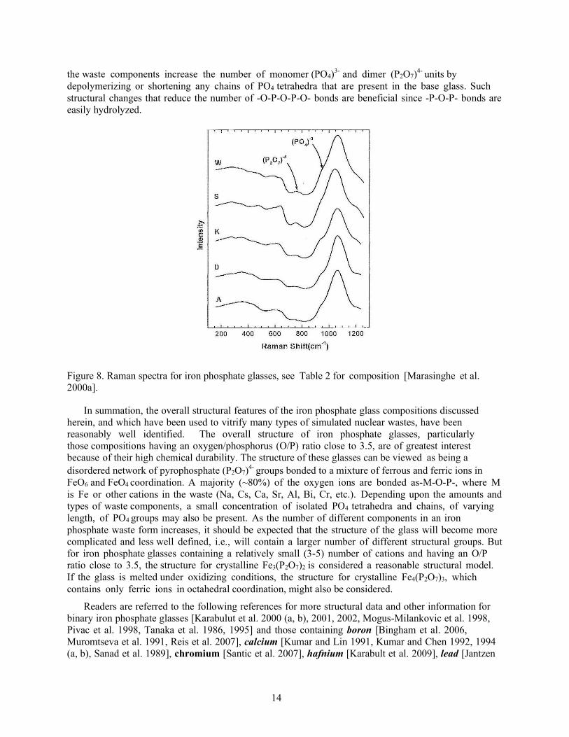
The Raman spectrum for glass A, the 40 Fe2O3-60 P2O5 mol%, base glass in Figure 8, was characteristic of a structure dominated by pyrophosphate, (P2O7)4-, groups [Mogus-Milankovic et al. 1997]. The changes in the Raman spectra with the addition of waste components are relatively small, but the band at ~750 cm-1, assigned to pyrophosphate groups, and the band at ~950 cm-1, assigned to isolated (PO4)3-, become more apparent, especially for glass W which contains 35 wt% of the Hanford T- 111 waste that contains 10 different oxides. These changes have been interpreted to mean that many of
14
the waste components increase the number of monomer (PO4)3- and dimer (P2O7)4- units by depolymerizing or shortening any chains of PO4 tetrahedra that are present in the base glass. Such structural changes that reduce the number of -O-P-O-P-O- bonds are beneficial since -P-O-P- bonds are easily hydrolyzed.
Figure 8. Raman spectra for iron phosphate glasses, see Table 2 for composition [Marasinghe et al. 2000a].
In summation, the overall structural features of the iron phosphate glass compositions discussed herein, and which have been used to vitrify many types of simulated nuclear wastes, have been reasonably well identified. The overall structure of iron phosphate glasses, particularly those compositions having an oxygen/phosphorus (O/P) ratio close to 3.5, are of greatest interest because of their high chemical durability. The structure of these glasses can be viewed as being a disordered network of pyrophosphate (P2O7)4- groups bonded to a mixture of ferrous and ferric ions in FeO6 and FeO4 coordination. A majority (~80%) of the oxygen ions are bonded as-M-O-P-, where M is Fe or other cations in the waste (Na, Cs, Ca, Sr, Al, Bi, Cr, etc.). Depending upon the amounts and types of waste components, a small concentration of isolated PO4 tetrahedra and chains, of varying length, of PO4 groups may also be present. As the number of different components in an iron phosphate waste form increases, it should be expected that the structure of the glass will become more complicated and less well defined, i.e., will contain a larger number of different structural groups. But for iron phosphate glasses containing a relatively small (3-5) number of cations and having an O/P ratio close to 3.5, the structure for crystalline Fe3(P2O7)2 is considered a reasonable structural model. If the glass is melted under oxidizing conditions, the structure for crystalline Fe4(P2O7)3, which contains only ferric ions in octahedral coordination, might also be considered.
Readers are referred to the following references for more structural data and other information for binary iron phosphate glasses [Karabulut et al. 2000 (a, b), 2001, 2002, Mogus-Milankovic et al. 1998, Pivac et al. 1998, Tanaka et al. 1986, 1995] and those containing boron [Bingham et al. 2006, Muromtseva et al. 1991, Reis et al. 2007], calcium [Kumar and Lin 1991, Kumar and Chen 1992, 1994 (a, b), Sanad et al. 1989], chromium [Santic et al. 2007], hafnium [Karabult et al. 2009], lead [Jantzen

15
1986, Sales and Boatner 1988, Sales et al. 1985, Greaves et al. 1988, Doweidar et al. 2006, Boatner, US Patent 1994, Reis et al. 2002(a, b), Santic et al. 2011, Mogus-Milankovic et al. 2005], manganese [Inamura et al. 1995], potassium [Nishida et al. 1981, Moustafa et al. 1999], sodium [Concas et al. 1995 (a, b), Guomei et al. 1994, Menil et al. 1979, Musinu et al. 1996, Mogus-Milankovic et al. 1996, Lin et al. 1989, Topic et al. 2000, Mogus-Milankovic et al. 2001c, Russo et al. 2008, Itoh et al. 1995], technetium [Xu and Heo 2012], tellurium [Tanaka et al. 1990], uranium [Sytko and Pershina 1995, Ramsay et al. 1994, Russo et al. 2008, Rodriguez et al. 2013], vanadium [Oohata et al. 1994], plutonium [Meaker et al. 1996, Ramsay et al. 1994], zinc [Reis et al. 2001, Sales and Otaigbe 1998 and Jermoumi et al. 2002] and other phosphate glasses containing lead–indium and lead-scandium [Suzuya et al. 1999], strontium-molybdenum [Mogus- Milankovic et al. 2003b].
3. IRON PHOSPHATE GLASS WASTE FORMS: LABORATORY SCALE MELTS
Data is available for a large number of iron phosphate glass waste forms that meet the DOE’s waste form acceptance criteria and that contain a wide range of low and high activity nuclear wastes (LAW and HLW) [Day et al. 1998, 2011, 2012, Day and Kim 2003, Huang et al. 2002, 2004 (a, b); 2005, Kim CW et al. 2003 (a, b, c), 2004, Leerssen 2002, Marasinghe et al. 2000a, Mesko et al. 1998a, 1999, Ray 2009]. The majority of these studies used glasses prepared in laboratory scale quantities, but data on manufacturing iron phosphate glass waste forms in larger amounts during continuous processing are also available [Sevigny et al. 2011, Soelberg and Rossberg 2011]. A list of 53 different iron phosphate waste form compositions containing several different types of wastes has been compiled from the literature [Pierce and Day 2011]. These compositions are shown in the “ternary” diagram in Figure 1. Although the list is incomplete, it provides a comprehensive data base supporting the versatility and compositional tolerance of iron phosphate glass for vitrifying nuclear wastes, and the potential use of iron phosphate glass in waste immobilization technology.
A summary of the iron phosphate glass waste forms containing various types of wastes, that have an excellent chemical durability, is given in Table IV along with the maximum waste loading (WL) achieved, to date, for each waste form. The simplified waste compositions, in wt% oxides, used in these waste forms are shown separately in Table V. Many of the maximum waste loadings for these iron phosphate waste forms exceeded those reported for other oxide glasses.
The glass forming chemicals/additives added to the waste, the melting temperature, the techniques employed to measure the chemical durability and the corresponding references are listed in Table IV. It is important to note that in a majority of instances, only two glass forming chemicals, namely P2O5 and Fe2O3, were added to the waste and only one was needed for the high-chromium HLW waste. This feature of iron phosphate glass is highly beneficial, since it reduces the volume of the vitrified waste form as well as simplifying the handling and cost of glass forming chemicals (GFC).
In some cases, the waste loadings given in Table IV could be even higher, but it has been limited by the need to keep the melting temperatures at or below 1250oC so that the overall composition might be processed in a Joule Heated Ceramic Melter (JHCM). The maximum operating temperature of a JHCM is limited by the melter components, particularly the metal electrodes. In the absence of a processing temperature limitation, such as in a Cold Crucible Induction Melter (CCIM), it should be possible to achieve waste loadings that are higher than those listed in Table IV for the iron phosphate waste forms. A more detailed account of the various iron phosphate waste forms listed in Table IV along with a description of the types of nuclear wastes they contain are given in the following section.

16
3.1 Waste Forms Containing
3.1.1 Hanford HLW Sludges; C-106, B-110, C-112, T-111, and TFB
Iron phosphate waste forms containing simplified versions (Table V) of otherwise very complex compositions of the Hanford HLW sludge wastes, C-106, B-110, C-112, T-111 and TFB have been produced in crucible size quantities and their key properties, especially chemical durability, have been carefully measured [Mesko et al. 1998 (a, b), Day et al. 1998]. These wastes were generated from spent nuclear fuel (SNF) when reprocessed to recover Pu and U for reuse in new fuel. The C-106 waste was generated by reprocessing SNF using the PUREX (Plutonium Uranium Refining by Extraction) process, while the B-110, T-111 and C-112 wastes were generated by the BP (Bismuth Phosphate) refining process.
These HLWs have been successfully vitrified to in iron phosphate glass by simply adding P2O5
and, in one case (C-112 sludge), adding P2O5 and small amounts of Fe2O3 to the waste. These glassy waste forms, containing up to 50 wt% waste, were easily melted below 1200°C in 1 h, and met all the DOE chemical durability requirements. Vitrification of these particular HLW sludge wastes, which contain P2O5 and considerable amounts of Fe2O3, in an iron phosphate glass, takes advantage of these components present in the waste. This minimizes the amount of glass forming materials that are needed, the volume of glass that must be produced (in the WTP), and the disposal cost.

17
Table IV: Chemically durable iron phosphate glass waste forms containing various types of nuclear wastes.
Type of Waste (For simulated waste
compositions, see Table V)
Highest Waste Loading (WL)
(wt%)
Primary Glass Forming and
Other Additives
Measured Chemical Durability Melting
Temperature (°C)
References PCT1 VHT2
CIT3 (Dissolution Rate, DR)
HLW: Hanford Tanks C-106, B- 110, C-112, T-111
20 (C-106),
50 (B-110, T-
111), 60 (C-
112)
P2O5, Fe2O3 Yes No Yes 1050-1200 Mesko et al. 1998a; Marasinghe et al. 2000a
High Na2O HLW, TFB (Hanford)
40 P2O5, Fe2O3 Yes No Yes 1015-1200 Day et al. 1998
Al-clad, highly enriched U, Spent Nuclear Fuel (SNF)
15 P2O5, Fe2O3,
CaF2 and/or Na2OYes No Yes 1150-1250 Mesko et al. 1999
High Chromium HLW 75 P2O5 Yes Yes Yes 1150-1250 Day et al. 2003b, Huang et al. 2002; Huang et al. 2004 a, b; Huang et al. 2005
High Na2O/Al2O3/sulfate SBW
(INL) 40 - 45 P2O5, Fe2O3 Yes Yes Yes 1000
Day et al. 2003b, Kim CW et al. 2003 a, c; Leerssen 2002
High MoO3 containing SNF (INL)
30 P2O5, Fe2O3 Yes No Yes 1200 Ryan et al. 2009, Ray 2009
40 P2O5, Fe2O3 Yes No Yes 1400 Ryan et al. 2009, Ray 2009
High sodium/sulfur LAW
(Hanford) 30 P2O5, Fe2O3 Yes Yes No 1050
Day et al. 2003 (a, b), Leerssen 2002; Kim CW et al. 2003 b; 2004
High sodium/sulfur AZ102
LAW (Hanford) 26
P2O5, Fe2O3,
SiO2, Al2O3, Bi2O3, Cr2O3, CaO, ZnO,
ZrO2
Yes Yes No 1050 Day et al. 2011, 2012
1PCT: Product Consistency Test; 2VHT: Vapor Hydration Test; 3CIT: Coupon Immersion Test

18
Table V: Simplified composition (wt%) of the simulated wastes vitrified in iron phosphate glass waste forms in Table IV.
Oxides High Level Waste (HLW) LAW SNF R-SNF
C-106 B-110 C-112 T-111 TFB High
ChromSBW
Average LAW
AZ102 Al-cladHigh Mo
Al2O3 17.70 2.70 4.20 1.10 1.30 21.00 27.80 4.40 0.27 87.18
B2O3 0.40 0.10
BaO 1.20 0.19 8.88
Bi2O3 25.80 29.80 6.70 3.00
CaO 1.50 16.10 3.40 3.00 2.20
CeO2/Ce2O3 4.40 0.36 11.08
Cl 0.90 0.60 0.14
Cr2O3 4.00 0.20 0.40 0.81
Cs2O 0.50 0.32 11.79
CuO 3.80
F 0.80 0.80 1.60 0.60
Fe2O3 16.80 30.60 15.00 26.30 8.30 9.00 1.40
K2O 7.60 3.01
La2O3 5.10 1.00 0.40 0.18 18.65
MgO 2.50
MnO/MnO2 10.40 0.50 0.80
MoO3 0.60 13.92
Na2O 22.10 14.40 7.10 5.60 54.60 26.00 52.30 75.30 77.04
Nd2O3 6.20 0.56 18.65
NiO 9.50 0.20
P2O5 1.30 1.70 14.10 3.60 14.90 5.00 1.60 7.70 0.22
PbO 1.10 0.90
Re2O7 0.10
SO3 2.50 0.20 3.60 9.50 16.79
SnO2 0.25
SrO 0.16 3.11
SiO2 34.70 23.40 11.30 0.80 16.00 0.50 0.43
TeO2 2.75
UO2 30.50 3.30 9.00 8.90
ZnO
ZrO2 0.20 3.00 0.66 10.92
Other* 0.89
Total 100.1 100.1 100.1 99.9 100 100 100 100 100.01 100 100
LAW: Low Activity Waste; SNF: Spent Nuclear Fuel; R-SNF: Reprocessed Spent nuclear Fuel
* Other: 0.06 Rb2O, 0.09 Y2O3, 0.16 Pr2O3, 0.09 Sm2O3, 0.01 Eu2O3, 0.26 RuO2, 0.06 RhO2, 0.04 PdO, 0.02 Pm2O3, 0.05 NpO2, 0.05 PuO2.

19
The composition of the TFB waste in Table V [Day et al. 1998] was calculated to be the average composition of the sludge in all the tanks in Tank Farm B at Hanford. Like the C-106, B-110, C-112, and T- 111 wastes, the TFB waste also contains considerable amounts of P2O5 and Fe2O3, but its alkali (Na2O) content is much higher than the other wastes, see Table V. Up to 40 wt% of the simulated TFB waste was vitrified in an iron phosphate waste form and its chemical durability, as measured by either the CIT or PCT procedure met the DOE requirements, see section V, A.1 and A.2. These iron phosphate waste form compositions were melted and homogenized in less than 1.5 h at temperatures between 1015 to 1200°C which are within the operating range of a JHCM. Even though TFB compositions contain nearly 55 wt% sodium, the corrosion of the refractory crucible by the iron phosphate melt containing 40 wt% of the TFB waste was less than the corrosion that occurred when DWPF glasses were melted in a crucible of the same refractory (discussed later in section VI, C).
3.1.2 Hanford High Chromium HLW
The Hanford HLW has been divided into 17 compositional groups, called clusters, which contain varying amounts of Cr2O3, 4.25 wt% being the highest [Perez et al. 2001, Day et al. 2003b, Huang et al. 2004a]. Chromium oxide is one of several components commonly present in many nuclear wastes that are either insoluble or marginally soluble in oxide melts. For example, the solubility of Cr2O3 in silicate melts is reported to be between 0. 5 and 1.0 wt% [Feng et al. 1996]. Thus, a HLW containing 4.25 wt% Cr2O3 would need to be diluted by ~4.5 to 9 times, or, said in another way, the waste loading would need to be limited to between 12 and 24 wt% to keep the Cr2O3 content of the waste form below 1 wt%.
Chromium oxide has a much higher solubility in iron phosphate melts. A simulated HLW containing 4 wt% Cr2O3, whose overall composition is representative of the high chromium oxide wastes at Hanford, has been vitrified in a phosphate glass by simply adding a source of P2O5 that formed chemically durable glassy waste forms with waste loadings (WL) as high as 65 wt% [Huang et al. 2003, 2004a]. Waste forms containing up to 80 wt% of the high chromium waste have been produced, but they contained small amounts, <1.5%, of Cr2O3 crystals. The melting temperature of the iron phosphate glasses varied with the WL, ranging from 1100°C at a WL of 35 wt% to 1300°C at a WL of 80 wt%. The melting temperature for the most chemically durable waste form, WL of 65 wt%, was 1200°C. The chemical durability of either glassy or partially crystallized waste forms with a waste loading of 75 wt% exceeded that of commercial window glasses. More information for the chemical durability of high chromium HLW waste forms is given in section V, A.1.
3.1.3 Hanford Low Activity Waste (LAW); Average LAW and AZ102 LAW
The Hanford site in Washington State has more than 55 million gallons of radioactive waste stored in 177 underground storage tanks [Perez et al. 2001]. The waste in these tanks consists of a settled sludge layer containing mainly heavy metals, transuranics and phosphates, and a liquid layer above it containing mainly dissolved sodium, nitrates, phosphates and sulfates. A majority of the radiation in these tanks is contained in the sludge layer, which is by definition a high level waste (HLW). The liquid fraction of the waste, which is of larger amount, is known as the low activity waste (LAW). According to the DOE’s current waste remediation strategy, the HLW and LAW fractions will be separated, vitrified independently in a borosilicate glass and stored in an underground repository.
The waste volume and compositions estimated with the Hanford Tank Waste Optimization Simulator (HTWOS) for the Tank Farm Contractors Operation and Utilization Plan (TFCOUP) [Kirkbride 2000] were used as the basis for developing a general composition for LAW. The HTWOS estimation produced about 900 batches of LAW of different compositions. A mass-weighted average composition for batches containing >7 wt% SO3 has been used in formulating borosilicate glass compositions for Hanford LAW. The average LAW composition shown in Table V is a simplified version of this composition. It was developed by neglecting the components whose concentration was <0.5 wt%, and

20
then normalizing the composition to 100%. Most LAW streams like the one in Table V are generally high in sulfate and sodium and both components can potentially limit the waste loading.
The composition of AZ102 LAW, Table V, which is the LAW fraction in Tank AZ102, is similar to the average Hanford LAW composition. However, it contains a much larger amount of SO3 (17 wt% compared to 10 wt%) and slightly larger amounts of total alkali (80 wt% compared to75 wt%). An investigation of the properties of iron phosphate waste forms containing either the average LAW or AZ102 composition yielded the following results.
1. Iron phosphate compositions containing 30 wt% average LAW or 26 wt% for AZ-02 LAW, designated as MS26AZ102F-2), both as-quenched and CCC-treated, with a Na2O content ranging from 20.5 to 22.5 wt% were melted at 1050°C/1100°C in 2 to 3 h. The iron phosphate waste forms satisfied the current PCT and VHT chemical durability standards [Day et al. 2003b, 2011, 2012, Day and Kim 2003, Kim CW and Day 2003b, Leerssen 2002]. Additional information for chemical durability of waste forms containing Hanford LAW is given in section V, A.1.
2. The processing of the MS26AZ012F-2 iron phosphate melt in a research size JHCM at PNNL (Sevigny et al. 2011) and CCIM at INL (Soelberg and Rossberg 2011) was successful. The slurry feed batch was melted without interruption for 10 days in the JHCM (PNNL) between 1030°C and 1050°C and for 70 h in the CCIM (INL) between 1030°C and 1090°C. The minimum and maximum melting rate was 411 and 1330 kg/m2/day, respectively, in the JHCM, and 285 and 664 kg/m2/day, respectively, in the CCIM.
3. There was no sulfate or corrosive sulfate salt liquids formed during crucible melting with dry raw materials or during continuous operation in the JHCM (PNNL) or CCIM (INL) using a slurry batch. This implies that the waste loading in these iron phosphate glasses is not limited by the SO3 content of the LAW, and about 4 to 5 wt% SO3 could be retained in iron phosphate glass waste form.
4. The retention of other volatile components like cesium and rhenium (surrogate for Tc-99) was from 92 to 100% for Cs2O and from 33 to 66% for Re2O7 for various melting conditions (oxidizing or reducing atmospheres and times, ranging from 3 h to 10 days).
5. Corrosion of commercial refractory materials such as alumino-silicate (SiO2 83%, Al2O3
17%), high purity alumina, and Monofrax K-3 is negligible to minimal, see section VI, C.
6. The corrosion of Inconel 690 and Inconel 693 metal coupons, determined by dimensional changes, corrosion depth, and chromium depletion, in iron phosphate melts containing 26 wt% AZ102 LAW at 1050 and 1100°C was within acceptable limits for use as electrodes in a JHCM (Gan et al. 2011). Inconel 693 performed significantly better in iron phosphate melts than Inconel 690.
7. The Inconel 693 electrodes used in the research scale JHCM experiments conducted at PNNL to melt (10 days) an iron phosphate glass that contained 26 wt% of AZ102 LAW had a corrosion rate of <2.5 mm/year [Sevigny et al. 2011] and ~1.6 mm/year [Hsu et al. 2014], two independent measurements. For comparison, the corrosion rate of Inconel 690 that is currently being used in JHCM’s at PNNL and in the DWPF at the Savannah River Site has been reported to range between 1.1 and 2.8 mm/year [Barnes et al. 1982, Iverson et al. 1984].
8. In similar studies conducted using an iron phosphate melt that contained 30 wt% of the average LAW composition, see Table V, at 1050°C for up to 155 days, the corrosion rate was ~0.50 mm/year for Inconel 690 and ~0.28 mm/year for Inconel 693 [Zhu D et al. 2005]. For additional corrosion results see section VI, D.

21
9. The viscosity and electrical conductivity for iron phosphate melts containing Hanford LAW are within the acceptable limits for processing in a JHCM or CCIM.
3.1.4 INL Sodium Bearing Waste (SBW)
Radioactive wastes from nuclear fuel reprocessing at the Idaho Nuclear Technology and Engineering Center (INTEC) have been collected and calcined for several decades. In addition, secondary radioactive wastes from decontamination, laboratory activities, and fuel storage activities have also been stored, as liquid, which is collectively called sodium bearing waste (SBW). According to different estimates, from about 3.8 to 5.7 million liters (1 to 1.5 M gallons) [Peeler et al. 2001, Darab et al. 2001, Vienna et al. 1999] of these wastes are temporarily stored in stainless steel tanks at the Idaho National Engineering and Environmental Laboratory (INEEL), currently the Idaho National Laboratory (INL). These liquid wastes are considered high priority for immobilization, since as a liquid; they can easily contaminate the environment, thus posing a risk to humans and animals. Vitrification in a chemically durable glass is considered one means for immobilizing the SBW, although different options for pre- treating the liquid waste are being evaluated.
The sodium bearing waste is basically an acid solution with approximately 7M (NO3)2-. The other ionic species that are present in the solution at relatively high to moderate concentrations (>1 wt%) include, in decreasing order, [Vienna et al. 1999] Na+, Al3+, K+, SO4
2-, PO42-, Ca2+, Fe3+, Cl-, F-, and
Zr4+. Several different versions of simplified compositions based on oxide components for the SBW have been published [Peeler et al. 2001, Darab et al. 2001, Vienna et al. 1999, Kim CW et al. 2003 (a, b)], but all the differences are small. This difference in composition arises from the choices made in setting the lower limit for the concentration of components that may be excluded for simplifying the overall composition. The simplified compositions listed in Table V were generated by neglecting components present in quantities <0.1 wt% in the original SBW, and normalizing to 100 wt% to account for the excluded mass.
The SBW composition is relatively high in sodium, aluminum and sulfate, Table V [Peeler et al. 2001, Leerssen 2002, Day et al. 2003b, Kim CW et al. 2003 (a, b)]. Glass formulations based on borosilicate compositions for the direct vitrification of SBW were first developed by Vienna et al. (1999), and later extended by Peeler et al. (2001). It was concluded that the presence of sulfur species in the SBW would limit the SBW loading in the glass. The solubility limit for sulfates in silicate melts is generally <1 wt% according to these studies. This low solubility limits the WL to a maximum of 20 wt% (Darab et al. 2001). In an iron phosphate melt at least 5 wt% SO3 can be present in the waste without forming a salt layer or inclusions [Kim DS et al. 2003] so higher waste loadings are possible.
Vitrification of a simulated SBW (see Table V) in an iron phosphate glass shows that a WL of 40 to 45 wt% can be achieved without any sulfate segregation or salt (gall) formation [Leerssen 2002, Kim CW et al. 2003(a, c)]. The waste forms satisfy all the current DOE requirements for chemical durability (CIT, PCT and VHT), see section V, A.1 and A.2. The limiting factor for the chemical durability appears to be the sodium content of the waste. The chemical durability of the waste form becomes unsatisfactory when the Na2O content exceeds about 23 wt%. As was the case for the chemical durability of the TFB sludge waste forms (section V, A.2), the presence of alumina is a significant factor in increasing the chemical durability of iron phosphate waste forms containing SBW waste. The iron phosphate compositions were melted at temperatures, between 950 and 1000°C, in 2 to 4 h, well within the capability of JHCM. The iron phosphate melt retained about 43% of the SO3 present in the batch.
3.1.5 Aluminum-Clad Spent Nuclear Fuel (SNF)
Spent nuclear fuel is highly radioactive and will remain so for millions of years due to the long half-lives of U-235 (7 x 10⁸ years) and the daughter products such as isotopes of Th, Pu, Np, Am, Cm
22
and others produced during use. Like other high or low level nuclear wastes, the management and disposal of SNF must be carefully considered to avoid the release of radioactivity into the environment.
Commercial nuclear fuel rods are clad with aluminum or more commonly with ZircalloyTM. Currently, 409 Al-clad highly enriched SNF rods are stored at the DOE Savannah River site and are being considered for permanent immobilization by vitrification. Present plans call for the SNF rods to be dissolved in a nitric acid solution which will be fed into a furnace along with glass forming chemicals, and melted to form a chemically durable glass. The vitrification process would be similar to that now being used to vitrify HLW at the DWPF in a JHCM.
The SNF waste composition is a complicated mixture of numerous elements, but dominated, as expected, mostly by Al and U. Assuming a two year burn up, a simplified SNF composition based on oxide basis is given in Table V in wt%, where Al2O3 and UO2 constitute the bulk, ~96 wt%, of the waste. The feasibility of using an iron phosphate glass for immobilizing this SNF waste has been investigated [Mesko and Day 1999]. Prior to vitrification, the SNF waste was diluted by adding depleted UO2 to lower the U- enrichment and to avoid the risk of criticality. At least 15 wt% of SNF waste at 8% enrichment has been processed in iron phosphate melts at temperatures <1150°C. The iron phosphate waste forms contained no crystalline solids and their chemical durability was as good as, and in several cases up to 15 times better than the DOE approved ARM-1 reference glass [Mesko and Day 1999], see section V, A.2.
3.1.6 Re-processed Spent Nuclear Fuel
In several countries, especially Europe and Japan, SNF rods are chemically reprocessed to extract Pu and U for reuse in new fuel. The residual high level wastes that contain fission products and minor actinides are then vitrified for safe disposal in a borosilicate glass. The US Department of Energy (DOE), has also created the Advanced Fuel Cycle Initiative (AFCI) program to develop and demonstrate a uranium extraction (UREX+) process for recycling SNF [Ryan et al. 2009]. The current base line AFCI/UREX+ process generates several secondary waste streams which, depending upon the specific separation process, have different compositions. In one of these waste streams the dominant waste elements are lanthanides, ZrO2, alkalies, alkaline earths, MoO3, and noble metals (PdO, Rh2O3, and RuO2). The concentrations of MoO3 are predicted to vary from 1.35 to 13.99 mass%, ZrO2 from 3.04 to 13.75 mass%, and noble metals from 0.96 to 19.60 mass%. With regards to waste loading, two limiting compositions, representing extreme end points, that are expected to result from the separation processes, have been identified [Ryan et al. 2009, Crum et al. 2009, Riley et al. 2009];
1. a waste composition high in MoO3, generally referred to as Collins-CLT, and
2. a waste composition high in noble metals, referred to as Bakel-CLT.
The Mo-limited composition, Collins-CLT, is considered the most likely waste stream of all the base-line re-processed SNF compositions to be implemented [Ryan et al. 2009]. Studies on vitrifying this waste in a borosilicate (BS) glass showed that a waste loading (WL) of 18 wt% was the maximum that did not cause phase separation or crystallization of the melt on cooling [Ryan et al. 2009]. This translates to a maximum MoO3 solubility of about 2.5 wt%. Synthesis of multiphase borosilicate glass ceramic waste forms containing up to 50 wt% of this waste (MoO3 content 6.94 wt%) has been reported [Crum et al. 2011, 2012], but it is unknown whether the chemical durability of these waste forms meet DOE requirements.
In an attempt to increase the waste loading, the feasibility of using an iron phosphate glass to vitrify the Mo-dominated SNF waste, the simplified composition given in Table V was investigated (Ray 2009). Iron phosphate glasses have been reported [Selvaraj et al. 1985, Muthupari et al. 1996, Mogus- Milankovic et al. 2003a] to have a much higher solubility of MoO3, so a higher WL for this waste was expected.

23
Three series of base-line iron phosphate compositions, namely, X Fe2O3-(100-X) P2O5, mol% with X = 15, 20 or 25, containing different amounts (wt%) of the Mo-dominated SNF waste were investigated. The iron phosphate waste forms with a waste loading of 20 wt% were completely amorphous (MoO3
content is 2.78 wt%) and melted between 1150 and 1200°C in 2 h. The chemical durability (PCT and CIT dissolution rate) of the glass waste form containing the highest amount of Fe2O3 (Fe25PW20) met the DOE requirements, but the other two (Fe15PW20 and Fe20PW20) marginally failed. The density of these waste forms ranged from 3.1 to 3.7 g.cm-3, which lowers the volume of waste form compared with other oxide glasses of lower density.
The waste forms with WL >20 wt% were partially crystalline. The degree of crystallinity increased with increasing WL reaching ~2% at WL=30 and ~16% at WL=40. Interestingly, the chemical durability of the partially crystalline waste forms for all three compositional series improved with increasing WL and met all of the DOE standards. A waste loading of 40 wt% corresponded to a MoO3 content of 5.53 wt%. No molybdenum compounds were detected by XRD in the partially crystalline waste forms; rather the crystalline phases were lanthanum, neodymium or cerium phosphates. These results suggest that at least 5.53 wt% MoO3 can be dissolved in iron phosphate glasses.
The melting temperature for these glasses increased with WL. For example, it increased from 1200°C for the Fe25PW20 composition to 1400°C for the Fe25PW40 composition. The composition with 50 wt% WL did not fully melt at 1500°C. It is considered likely that chemically durable iron phosphate waste forms with WL >40 wt% of this Mo-dominated SNF waste could be produced in melters capable of operating at higher temperatures. These or similar iron phosphate compositions are considered to be suitable candidates for processing in a CCIM where higher operational temperature are possible.
3.1.7 Iron Phosphate Glass Waste Forms Containing Common and Important Components Present in Nuclear Wastes
Iron phosphate glasses containing various amounts of one or more components such as U, Cs, Bi, Na, K, Ca, Sr, or Mo, that are commonly present in many nuclear wastes, have been investigated [Marasinghe et al. 1999, 2000b]. Some of these compositions are listed in Table II. The primary purpose was to study the effect of these waste components on the redox equilibria of iron ions, and the structural features and crystallization characteristics of iron phosphate glasses. An estimate of the solubility limit of these components in the iron phosphate glasses was also made. The maximum amount of a component that could be incorporated before crystallization or phase separation occurred in the melt was used as the solubility limit.
These components, as oxides, were substituted for Fe2O3 or P2O5 or both in the base line 40Fe2O3-60P2O5, mol%, glass. Only those compositions which contained the maximum amount of these components and which produced glass upon melting and normal cooling are listed in Table VI. The maximum amount of a particular waste component that was present in the melt before detectable (XRD) crystallization occurred is given in column 2. These results show that a waste containing significant amounts UO2 or Cs2O can be vitrified in an iron phosphate glass.
A large part of the radioactive 137Cs and 90Sr stored at the Hanford site is present as CsCl and SrF2, so experiments were conducted [Mesko et al. 2000] to determine how much of these halides could be incorporated into iron phosphate glass. It should be noted that small amounts of halides in silicate melts often produce immiscibility which is undesirable for immobilization purposes. As described above, various amounts of CsCl or SrF2 were substituted for Fe2O3 or P2O5 or both in the base line 40Fe2O3- 60P2O5, mol%, composition, Table VI. Depending upon the amount of CsCl or SrF2, these glasses were melted between 950 and 1200°C in 1 to 2 h. The melting temperature decreased with increasing amount of CsCl/SrF2. The maximum amount that could be incorporated before crystallization was ~26 mol% (28 wt%) for CsCl and 31 mol% (31 wt%) for SrF2, Table VI. The chemical durability as

24
measured by PCT for these iron phosphate waste forms exceeded the DOE PCT requirements. Compositional analysis of the iron phosphate glasses showed that a majority of the halides was released during melting, but essentially all of the Cs and Sr were retained in the as-made glass.
4. CONTINUOUS MELTING OF IRON PHOSPHATE GLASS
4.1 Joule Heated Research Scale Melter (RSM/JHCM) at PNNL The ability to vitrify a wide range of nuclear wastes in chemically durable, iron phosphate waste
forms has been clearly demonstrated. A majority of this work has been conducted using small crucible scale melts. Unfortunately, no effort has been made, until recently, to investigate iron phosphate waste forms produced on a larger scale by continuously melting either a dry or wet slurry feed containing a simulated Hanford LAW.

25
Table VI: Data for selected iron phosphate waste forms containing components commonly present in nuclear waste.
Waste Component (Oxide)*
Waste Loading (mol%)**
Glass Composition Reference
Mol% Wt%
Bi2O3 20 20Fe2O3-60P2O5-20Bi2O3 15Fe2O3-41P2O5-44Bi2O3 Marasinghe et al. 1999, 2000a
Cs2O 30 28Fe2O3-42P2O5-30Cs2O 24Fe2O3-31P2O5-45Cs2O Marasinghe et al. 1999, 2000a
K2O 20 20Fe2O3-60P2O5-20K2O 23Fe2O3-63P2O5-14K2O Fang et al. 2000b
MoO3 30 10Fe2O3-60P2O5-30MoO3 11Fe2O3-59P2O5-30MoO3 Marasinghe et al. 1999
Na2O 20 32Fe2O3-48P2O5-20Na2O 39Fe2O3-52P2O5-9Na2O Marasinghe et al. 1999
20Fe2O3-60 P2O5-20 Na2O 25Fe2O3-66P2O5-9Na2O Fang et al. 2000b
Na2O+K2O 20 20Fe2O3-60P2O5-10Na2O-10K2O 24Fe2O3-64P2O5-5Na2O-7K2O Fang et al. 2000b
32Fe2O3-48P2O5-10Na2O-10K2O 38Fe2O3-50P2O5-5Na2O-7K2O Fang et al. 2000b
Na2O+Bi2O3 20 32Fe2O3-48P2O5-10Na2O-10Bi2O3 30Fe2O3-40P2O5-3Na2O-27Bi2O3 Marasinghe et al. 2000a
Na2O+CaO 20 32Fe2O3-48P2O5-10Na2O-10CaO 39Fe2O3-52P2O5-5Na2O-4CaO Marasinghe et al. 2000a
Na2O+Cs2O 20 32Fe2O3-48P2O5-10Na2O-10Cs2O 33Fe2O3-45P2O5-4Na2O-18Cs2O Marasinghe et al. 2000a
Na2O+UO2 20 32Fe2O3-48P2O5-10Na2O-10UO2 33Fe2O3-45P2O5-4Na2O-18UO2 Marasinghe et al. 1999, 2000a
SrO 20 32Fe2O3-48P2O5-20SrO 36Fe2O3-49P2O5-15SrO Marasinghe et al. 1999
UO2 15
25Fe2O3-60P2O5-15UO2 24Fe2O3-51P2O5-25UO2 Marasinghe et al. 1999, 2000a
26Fe3O4-59P2O5-15UO2 33Fe3O4-45P2O5-22UO2 Marasinghe et al. 1999
19 32Fe3O4-49P2O5-19UO2 38Fe3O4-36P2O5-26UO2 Marasinghe et al. 2000a
UO2+CaO 20 32Fe2O3-48P2O5-10UO2-10CaO 33Fe2O3-45P2O5-18UO2-4CaO Marasinghe et al. 2000a
CsCl 26 30Fe2O3-44P2O5-26CsCl 31Fe2O3-41P2O5-28CsCl Mesko et al. 2000
SrF2 31 24Fe2O3-45P2O5-31SrF2 27Fe2O3-45P2O5-28SrF2 Mesko et al. 2000
* The waste components were substituted for either Fe2O3 or P2O5 or both. **Maximum amount, mol%, before crystallization or phase separation occurs.

26
This important step was taken when an iron phosphate melt was processed in the joule heated, research scale melter (RSM) at PNNL [Sevigny et al. 2011, Day et al. 2012]. The waste chosen for this RSM/JHCM experiment was the Hanford AZ102 LAW because of its very high sulfate (~17 wt%) and alkali (~80 wt%) content. The optimum waste loading of 26 wt% was chosen from several crucible scale iron phosphate melts, see section III, A.4. This iron phosphate composition is hereafter designated as MS26AZ102F-2.
The RSM at PNNL, whose detailed description and operating parameters are given elsewhere [Sevigny et al. 2011], was operated continuously for 10 days at temperatures between 1030 and 1050°C. The iron phosphate melt (MS26AZ102F-2) was drained periodically through a pour spout tube (InconelTM 690) into a stainless steel canister for cooling. The primary objectives were to determine the operational capability of the joule heated RSM to process an iron phosphate melt and to obtain as much data as possible for assessing the feasibility of conducting larger, pilot-plant scale melting operations. The purpose of the pilot-plant size operations is to demonstrate the feasibility of vitrifying Hanford LAW and HLW waste streams in an iron phosphate melt on a scale more relevant to Hanford operations.
The RSM capability at PNNL is representative of a full-scale melter system and is useful for determining the relationships between the properties of the feed and the final glass waste form. The body of the RSM is an Inconel 625 closed-ended cylinder lined with a commercial (Alfrax) refractory that contained a Monofrax K3 refractory melt cavity (cavity diameter 15 cm, height 17 cm, inside volume 4.5 L). An electric kiln surrounded the melter body to minimize heat loss during operation. The RSM was equipped with an off- gas treatment system that included quenching, wet scrubbing, and high efficiency mist elimination, thereby, allowing direct assessment of effluent partitioning behavior.
Some of the most important goals of the RSM experiment were to determine the following:
1. could an iron phosphate melt be successfully processed in the joule heated RSM, over a 10 day period, without damaging the Inconel 693 electrodes, refractory lining and other melter components,
2. would the iron phosphate waste form meet the DOE requirements for chemical durability,
3. what glass production rates were possible and how did these rates vary with the melter atmosphere,
4. the percent retention of sulfate, cesium and other volatile species in the waste form and,
5. were any unexpected problems encountered.
Two Inconel 693 electrodes (dimension 7.6 cm x 7.6 cm) introduced from the top of the melter body and submerged in the iron phosphate melt supplied joule heating power to the melt in the RSM. A voltage of 10 to 35 V, an average current of 120A, and a current density of 1.6 to 3.5 A.cm-2 were maintained between the electrodes during the melting operation. Initially, the melter was loaded with a sufficient amount of pre- melted glass frit (start-up glass) of the same composition as that of the glass waste form to be processed. The starter glass was melted by turning on the melter kiln heater prior to initiating joule heating of the glass. The melt was agitated by injecting air at a rate of 1 to 1.5 L/min through a submerged Inconel 625 tube to enhance the feed and melt processing rates. The pour spout tube used for discharging the melt was heated to prevent feed line clogging and facilitate draining of the molten glass. Additional operational details are described in [Sevigny et al. 2011].
Once joule heating of the melt was established, the batch feed line was opened for continuous delivery of the slurry feed to the melter. The feed was delivered from a feed tank to the RSM feed nozzle by a peristaltic pump. An agitator in the feed tank kept the slurry well mixed. The feed tank was on a scale that was monitored by the computer data acquisition and control system. The pump speed and, hence, the rate at which the feed was introduced into the melter was controlled from the computer.

27
During the operation of the RSM, the melter conditions were varied in the following ways: (1) sugar was added to the slurry feed as a reductant to control NOx emissions and melt foaming and, (2) the melt was bubbled with air for the purpose of simulating conditions which are part of the current WTP plant design. Four different combinations of variables, namely, (1) no sugar/no air bubbler, (2) no sugar/air bubbler, (3) sugar/no air bubbler, and (4) sugar/air bubbler were used during the test procedures. Although, these parametric variables are likely to affect the major processing conditions such as the melt temperature, melter pressure, feed composition and rate, plenum temperature, cold cap coverage, off-gas temperature and quench-scrubber condensate temperature, efforts were made to maintain similar processing conditions when the variables were changed.
The 10 day RSM experiment was successful and the vitrification of the Hanford AZ102 LAW waste in the iron phosphate glass, waste loading was 26 wt%, progressed as planned. These encouraging test results support the conclusion that iron phosphate compositions can be safely processed in joule heated melters at a larger pilot-plant scale when equipped with Inconel 693 electrodes. The noteworthy information gained from the RSM experiment is summarized below.
1. This successful test produced about 124 kg of an iron phosphate glass waste form containing 26 wt% of AZ102 LAW (MS26AZ102F-2) during continuous operation for 240 h at production rates ranging from 0.31 to 1.0 kg/h (411 to 1330 kg/m2/day). Bubbling the melt with air or adding sugar to the slurry batch increased the glass processing rate. When both were used simultaneously, the glass production rate more than doubled.
2. The glass waste form prepared with or without sugar met all the chemical durability requirements (PCT and VHT) for LAW, see section V, A.1 for details of the chemical durability results. For example, the PCT results for the as-made and CCC-treated waste forms collected at different times during the 10 day experiment had a release rate for Na between 1.3 and 2.7 g/L, which is well below the DOE limit of 4 g/L for LAW. The VHT corrosion rate for the as-made glass waste forms was negligible (ranged from <0.5 to 2.6 g/m2/day), the DOE limit being 50 g/m2/day. The VHT results for the CCC treated samples, which were partially crystalline and not so consistent, were attributed to uneven crystallization and ranged from ~25 to 140 g/m2/day.
3. The iron phosphate melt containing 4.7 wt% SO3 was easily processed, with no detectable evidence of sulfate segregation. The average retention for SO3 and rhenium (surrogate for Tc) was 38 and 36 percent, respectively, for the entire 10 day experiment. The maximum retention for SO3 and rhenium was 78 and 61 percent, respectively. Adding sugar decreased the SO3 retention and increased Re retention.
4. The retention of SO3 was only marginally reduced when the melt was bubbled with air, but the retention was ~23% when sugar was added to the batch, see Figure 9. As expected, the addition of sugar created reducing conditions and increased the fraction of Fe2+ in the glass waste form (Figure 9, Table II).
5. No noticeable change or damage was observed in the melter electrodes, or the metal bubbler and melt discharge tubes. The edges of the Inconel 693 electrodes remained sharp after 10 days of operation see section VI, D. Based on the electrode dimensions, as measured from SEM photos, the corrosion rate of the Inconel 693 electrode was <2.5 mm/year [Sevigny et al. 2011] and ~1.6 mm/year [Hsu et al. 2014], two independent measurements. For comparison, the corrosion rate of the Inconel 690 that is currently used in the DWPF (SRNL) is reported to range between 1.1 and 2.8 mm/year [Barnes et al. 1982, Iverson et al. 1984].

28
Figure 9. Concentration of SO3 as a function of iron redox for the MS26AZ102F-2 glasses prepared at RSM (JHCM)-PNNL under different melting conditions [Sevigny et al. 2011, Day et al. 2012]
Overall, the RSM experiment to vitrify the Hanford AZ102 LAW in an iron phosphate melt in the joule heated RSM at PNNL provided useful and encouraging information in terms of overall melter performance, feed input and melt production rates, glass quality and chemical durability, retention of volatile components, especially SO3, and performance and minimal corrosion of the melter electrodes (Inconel 693), refractory lining and bubbler and melt discharge tubes [Sevigny et al. 2011].
4.2 Bench Scale Cold Crucible Induction Melter (CCIM) at KRI (Russia) and INL (USA)
As a means of vitrifying high and low level nuclear wastes (HLW and LAW), only the JHCM design discussed above is currently being used by DOE for glass melting. At the present time, the maximum operating temperature of joule heated melters in the US is limited by the Inconel 690 metal electrodes whose temperature limit is 1200°C.
As a potential alternative to the JHCM, Cold Crucible Induction Melters (CCIMs) have been developed which avoid the temperature limitations of a JHCM. The CCIMs have been developed and used outside the United States (US) for many years to vitrify HLW, intermediate level waste (ILW) and LAW [Girold et al. 2008, Stefnovsky et al. 2010].
The CCIM design concepts make use of induction heating from an induction coil through a melter shell (crucible) that is transparent to the induction field heating the melt. In this design, the induction coil does not directly contact the molten glass, but instead surrounds an array of vertically oriented water-cooled metal tubes. The assembly of water-cooled metal tubes acts as a kind of crucible and contains the molten pool of glass. The water cooling freezes the outer layer of the melt around the periphery and at the bottom of the melt. This forms a type of “cold crucible” of the same glass composition. Since no metal electrodes or refractory materials are required in a CCIM for heating or containing the melt, the corrosion of glass contact refractories and metal electrodes present in a JHCM are absent in a CCIM. Thus, a CCIM should ideally have a longer melter life and be capable of operating at temperatures higher than those in a JHCM.

29
The feasibility of processing iron phosphate glasses in a continuously operated CCIM has been investigated in two experiments and both produced encouraging results. In one experiment, the SBW (Table V) at INL was vitrified in an iron phosphate glass at a waste loading of 40 wt% in a CCIM at the V. G. Khlopin Radium Institute (KRI) in St. Petersburg, Russia [Kim CW et al. 2003 (a, b), Gombert and Richardson 2001, Gombert et al. 2002]. In the second experiment, the same iron phosphate glass composition containing 26 wt% of the Hanford AZ102 LAW (MSAZ102F-2), as was used in the research size JHCM at PNNL (section IV, A), was vitrified in a bench scale CCIM at INL [Soelberg and Rossberg 2011, Day et al. 2012].
4.2.1 Bench Top CCIM Experiment at KRI
The KRI bench-top CCIM consisted of a six turn vertical induction coil with an internal diameter of ~12 cm which surrounded a 9 cm diameter, 40 cm tall water cooled metal tube assembly that acted as the melter crucible [Gombert and Richardson 2001, Gombert et al. 2002]. A batch weighing ~1000 g of an iron phosphate composition containing 40 wt% of the simulated SBW (Table V) was prepared by thoroughly mixing appropriate amounts of the raw materials and melted in the KRI CCIM for 1 h [Kim CW et al. 2003 (a, b), Gombert and Richardson 2001]. The exact melting temperature was not measured/known, but based on the results, is estimated to have been above 1000°C as determined from a crucible-scale melt of an identical composition (section III, A.3). The overall glass composition was 50.3P2O5-9.7Fe2O3-40(SBW), wt%, and the batch materials used were mostly dry powders except H2SO4
and H3PO4 acids which were used as the sources for SO3 and P2O5, respectively. About 18 g of a sacrificial, electrically conducting material (silicon carbide) was mixed with the batch to initiate the melting process. Once the batch was melted, the heating was continued by an eddy current established in the melt. After melting, ~800g of glass was obtained, indicating a mass loss of 21 wt% due to the loss of volatile components and an unknown amount of material/glass adhering to the water-cooled metal tubes. The as-produced iron phosphate glass waste form was designated as IP40WG- CCIM, whereas, it’s identical counterpart produced by crucible scale melting (section III, A.3) was designated as IP40WG.
The noteworthy results for these SBW containing iron phosphate glass waste forms are noted below.
1. An iron phosphate composition containing 40 wt% SBW was produced in a CCIM and by conventional melting at 1000oC. No evidence of sulfate segregation was observed in either case.
2. The chemical durability of the waste forms, as measured by PCT, VHT and CIT exceeded that of the reference EA glass; see section V, A.1 and Table VII.
3. The waste forms prepared by conventional melting (IP40WG) and CCIM (IP40WG-CCIM) procedures, had the same density (Table VII).
4. The chemical durability and thermal properties for the IP40WG-CCIM waste forms differed slightly from those of the IP40WG waste forms. It is suspected that this difference is due to the higher Fe2+ concentration in the IP40WG-CCIM glass (56% compared to 11%), Table VII.
5. The h ighe r Fe2+ concentration in the IP40WG-CCIM waste form is attributed to the presence of SiC used as a starter material in the batch, which created reducing conditions in the melt.

30
Table VII. Selected properties of iron phosphate glass waste forms containing 40 wt% SBW and prepared by conventional melting (IP40WG) and CCIM processing (IP40WG-CCIM) [Kim CW et al. 2003 (a, b), Gombert and Richardson 2001].
Properties IP40WG IP40WG-CCIM
Density, g/cm3 2.76 ± 0.01 2.76 ± 0.01 1Glass transition temperature Tg, °C 430 ± 3 420 ± 3 1Crystallization temperature Tx, °C 590 ± 3 560 ± 3 1Melting temperature Tl, °C 740 ± 3 718 ± 3 2Fe2+ fraction 0.11 0.56 3VHT corrosion rates, g/m2/day <0.2 40 1 Measured by DTA. 2 Fe2+ fraction = Fe2+/[Fe2+ + Fe3+] measured by Mössbauer spectroscopy. 3 No DOE specified limit for VHT for HLW is available for comparison; but that for LAW is 50 g/m2/day.
4.2.2 Bench Scale CCIM Experiment at INL
As mentioned before, the CCIM experiment at INL was conducted to demonstrate the vitrification of a Hanford LAW that contains large amounts of sulfate and alkali compared to other Hanford waste streams, in an iron phosphate glass. The same MSAZ102F-2 composition that contained 26 wt% of the Hanford AZ102 LAW, that was used in the RSM/JHCM experiment at PNNL was also used for the CCIM experiment at INL.
The CCIM cylindrical crucible wall consisted of vertical water-cooled tubes [Soelberg and Rossberg 2011] an internal diameter of 26.7 cm, and a height of 40.6 cm. This apparatus was surrounded by a cylindrical induction coil assembly. A conductive metal cage enclosed the melter and induction coil system for safety purposes and to protect the equipment. The equipment was operated in a continuous fashion using a slurry batch feed of the MS26AZ102F-2 composition and included the following sub-systems; (1) induction power system, (2) feed system, (3) melter system, (4) glass product draining system, (5) cooling water system, (6) off-gas control system, and (7) process monitoring and control system.
Instead of using SiC powder to initiate heating as in the KRI CCIM (section B.1 above), pre-melted glass frit of the same MS26AZ102F-2 composition was used as the starter glass in the CCIM at INL. The electrical conductivity of a MS26AZ102F-2 glass is sufficiently high that it is self-heating. The slurry feed was started after the start up glass was molten and the melt attained the desired temperature (~1030°C). The melt was bubbled with air using an Inconel 625 tube and an air flow of between 1 and 1.5 L/m. Bubbling accelerated the mixing (thermal convection currents) and homogenization of the melt and which permitted a higher feed rate (from 0.86 L/h to 2.0 L/h) and glass production rate (from 0.66 kg/h to 1.5 kg/h). To control NOx emission and foaming, about 25 g of sugar per liter of slurry was added to the slurry batch. In the RSM experiment at PNNL, sugar was added at 50g per liter to the slurry feed at certain times.
The noteworthy results obtained from the CCIM experiment at INL are as follows.
1. The CCIM operated continuously for 70 h at temperatures between 1030 and 1090°C producing a homogeneous iron phosphate glass, designated as MS26AZ102F-2. The batch contained 26 wt% of the Hanford AZ102 LAW (4.7 wt% of SO3) and melted without forming any detectable sulfate layer or “gall” layer. The density of the glass collected at different times varied only nominally, between 2.79 and 2.85 g/cm3.
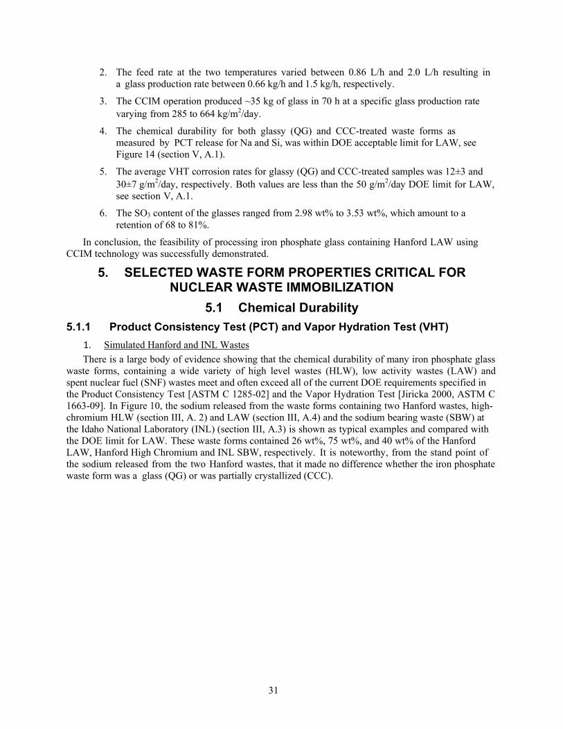
31
2. The feed rate at the two temperatures varied between 0.86 L/h and 2.0 L/h resulting in a glass production rate between 0.66 kg/h and 1.5 kg/h, respectively.
3. The CCIM operation produced ~35 kg of glass in 70 h at a specific glass production rate varying from 285 to 664 kg/m2/day.
4. The chemical durability for both glassy (QG) and CCC-treated waste forms as measured by PCT release for Na and Si, was within DOE acceptable limit for LAW, see Figure 14 (section V, A.1).
5. The average VHT corrosion rates for glassy (QG) and CCC-treated samples was 12±3 and 30±7 g/m2/day, respectively. Both values are less than the 50 g/m2/day DOE limit for LAW, see section V, A.1.
6. The SO3 content of the glasses ranged from 2.98 wt% to 3.53 wt%, which amount to a retention of 68 to 81%.
In conclusion, the feasibility of processing iron phosphate glass containing Hanford LAW using CCIM technology was successfully demonstrated.
5. SELECTED WASTE FORM PROPERTIES CRITICAL FOR NUCLEAR WASTE IMMOBILIZATION
5.1 Chemical Durability
5.1.1 Product Consistency Test (PCT) and Vapor Hydration Test (VHT)
1. Simulated Hanford and INL Wastes
There is a large body of evidence showing that the chemical durability of many iron phosphate glass waste forms, containing a wide variety of high level wastes (HLW), low activity wastes (LAW) and spent nuclear fuel (SNF) wastes meet and often exceed all of the current DOE requirements specified in the Product Consistency Test [ASTM C 1285-02] and the Vapor Hydration Test [Jiricka 2000, ASTM C 1663-09]. In Figure 10, the sodium released from the waste forms containing two Hanford wastes, high-chromium HLW (section III, A. 2) and LAW (section III, A.4) and the sodium bearing waste (SBW) at the Idaho National Laboratory (INL) (section III, A.3) is shown as typical examples and compared with the DOE limit for LAW. These waste forms contained 26 wt%, 75 wt%, and 40 wt% of the Hanford LAW, Hanford High Chromium and INL SBW, respectively. It is noteworthy, from the stand point of the sodium released from the two Hanford wastes, that it made no difference whether the iron phosphate waste form was a glass (QG) or was partially crystallized (CCC).

32
Figure 10. Normalized sodium release, determined by the Product Consistency Test (PCT), from glassy (QG) or heat treated/partially crystallized(CCC)ironphosphate waste forms. Refs are Hanford LAW [Kim CW et al. 2003b], Hanford High Chromium HLW [Huang et al. 2004b], and Han Hanford TFB [Kim CW et al. 2003a]. Right hand bars denote DOE limit for LAW and HLW.
Vapor hydration test (VHT) results for iron phosphate waste forms, for the same three wastes in Figure 10, are shown below in Figure 11. The corrosion rates for the two glassy (quenched) Hanford wastes are less than 10% of the permissible DOE limit while the corrosion rate for the INL sodium bearing waste is barely measurable. The two heat-treated/partially crystallized (CCC) Hanford wastes (LAW and HLW) had a higher corrosion rate than the glassy waste forms, but still much below the DOE limit for LAW.
Figure 11. Corrosion rate as determined by the Vapor Hydration Test (VHT), for two Hanford HLW glass (quenched) and heat treated (CCC)/partially crystallized iron phosphate waste forms and INL SBW glassy waste form. Waste loadings and references are the same in Figure 10.

33
The IP40SBW iron phosphate waste form whose corrosion rate is shown in Figure 11, contained 40 wt% of the INL sodium bearing waste (SBW). Another 1000 gram batch of this same iron phosphate waste form composition was melted for one hour in an experimental cold crucible induction melter (CCIM) at the V. G. Khlopin Radium Institute in Russia [Gombert 2001, 2002] (section IV, B). The normalized elemental mass release for the conventionally melted, (IP40WG) and CCIM melted (IP40WG-CCIM) iron phosphate waste forms are shown in Figure 12 along with the elemental release data for the DOE environmental assessment (EA) glass. While there are small differences between the two iron phosphate waste forms melted in the US and in Russia, it is clear that the elemental release of sodium (Na) from both iron phosphate glasses is 3 to 7 times smaller (higher chemical durability) than the Na release from the EA glass. Sodium is the only common element in the two iron phosphate glass waste forms and the EA glass. The dissolution rate (DR) in deionized water at 90°C for these glasses was measured by the CIT technique described in the next section (A.2). The results are compared in Figure 13, which also show that the IP40WG and IP40WG-CCIM iron phosphate waste forms are more chemically durable than the standard EA glass.
Figure 12. Comparison of the normalized elemental mass release (g/m2) from a conventionally melted iron phosphate waste form (IPG40WG) and a CCIM melted waste form containing 40 wt% of the INL sodium bearing waste after PCT in DIW at 90oC for seven days. The environmental assessment (EA) glass is shown for comparison. Elements for which the mass release was <0.01 g/m2 are not shown. Sodium is the only element in common for all three glasses. The initial (pHi) and final (pHf) pH of the leachate is given for each glass. Si in CCIM melted sample (*) is from the sacrificial SiC used in the CCIM and (**) is the DOE requirement for HLW [Kim et al. 2003a].

34
Figure 13. Dissolution rate (DR) in DIW at 90°C as a function of immersion time for the iron phosphate glass waste forms containing 40 wt% SBW prepared using conventional melting (IP40WG) and CCIM procedures (IPWG40-CCIM), and the reference EA glass. Initial pH of DIW was 5.8. The nearly constant pH of the leachate for the IP40WG and IP40WG-CCIM samples compared to that for the EA glass attributed to the larger buffering action of the phosphate glasses.
The PCT normalized mass release of Na and Si for the iron phosphate glass waste form containing 26 wt% of AZ102 LAW, prepared in the RSM at PNNL (section IV, A) and in the CCIM at INL (section IV, B) is compared in Figure 14 along with the same composition waste forms prepared by several other melting procedures. As indicated in Figure 14, the normalized mass release of Na and Si from all of the iron phosphate waste forms, which were prepared in many different ways, was well below the DOE limit. The release of Na and Si from the heat treated/partially crystallized waste forms (CCC) was typically slightly higher than from the quenched glass (QC) waste forms, but the small difference is of little consequence.
This data, along with the other data acquired from these two 10 day experiments, is considered to be particularly relevant in terms of demonstrating (a) it is possible to vitrify a high alkali/high sulfate waste in an iron phosphate glass on a larger scale (although still small by practical needs) (b) no corrosive salt (gall) layer was present, (c) iron phosphate glass can be produced by joule heating (metal electrodes) or induction heating, (d) an iron phosphate melt can be drained from either type of furnace, and (d) the solidified iron phosphate waste form meets all required chemical durability requirements.
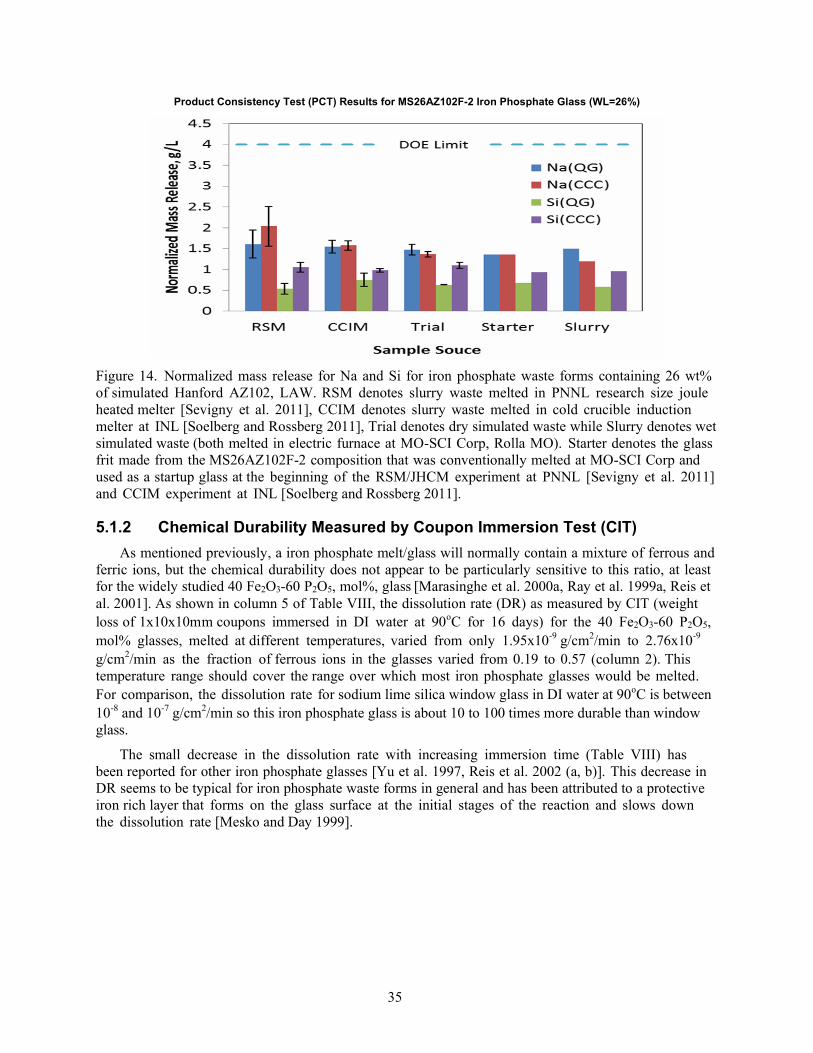
35
Product Consistency Test (PCT) Results for MS26AZ102F-2 Iron Phosphate Glass (WL=26%)
Figure 14. Normalized mass release for Na and Si for iron phosphate waste forms containing 26 wt% of simulated Hanford AZ102, LAW. RSM denotes slurry waste melted in PNNL research size joule heated melter [Sevigny et al. 2011], CCIM denotes slurry waste melted in cold crucible induction melter at INL [Soelberg and Rossberg 2011], Trial denotes dry simulated waste while Slurry denotes wet simulated waste (both melted in electric furnace at MO-SCI Corp, Rolla MO). Starter denotes the glass frit made from the MS26AZ102F-2 composition that was conventionally melted at MO-SCI Corp and used as a startup glass at the beginning of the RSM/JHCM experiment at PNNL [Sevigny et al. 2011] and CCIM experiment at INL [Soelberg and Rossberg 2011].
5.1.2 Chemical Durability Measured by Coupon Immersion Test (CIT)
As mentioned previously, a iron phosphate melt/glass will normally contain a mixture of ferrous and ferric ions, but the chemical durability does not appear to be particularly sensitive to this ratio, at least for the widely studied 40 Fe2O3-60 P2O5, mol%, glass [Marasinghe et al. 2000a, Ray et al. 1999a, Reis et al. 2001]. As shown in column 5 of Table VIII, the dissolution rate (DR) as measured by CIT (weight loss of 1x10x10mm coupons immersed in DI water at 90oC for 16 days) for the 40 Fe2O3-60 P2O5, mol% glasses, melted at different temperatures, varied from only 1.95x10⁻⁹ g/cm2/min to 2.76x10⁻⁹
g/cm2/min as the fraction of ferrous ions in the glasses varied from 0.19 to 0.57 (column 2). This temperature range should cover the range over which most iron phosphate glasses would be melted. For comparison, the dissolution rate for sodium lime silica window glass in DI water at 90oC is between 10-8 and 10-7 g/cm2/min so this iron phosphate glass is about 10 to 100 times more durable than window glass.
The small decrease in the dissolution rate with increasing immersion time (Table VIII) has been reported for other iron phosphate glasses [Yu et al. 1997, Reis et al. 2002 (a, b)]. This decrease in DR seems to be typical for iron phosphate waste forms in general and has been attributed to a protective iron rich layer that forms on the glass surface at the initial stages of the reaction and slows down the dissolution rate [Mesko and Day 1999].

36
Table VIII. Average dissolution rate, DR, in deionized water at 90°C after 4, 8, and 16 days for glasses made by melting a 40Fe2O3 - 60P2O5, mol%, composition at temperatures listed for 1 h.
Melting Temperature, (°C)
Fraction of Fe2+ (±0.02) DR±1.50 (10-9 g/cm2/min)
4 days 8 days 16 days
1150 0.17 3.50 2.95 2.19
1200 0.19 1.46 2.58 1.95
1350 0.42 3.09 4.00 2.76
1400* 0.57 4.51 3.09 2.66 * Melted for 2 h
Based on an increasing body of evidence [Day et al. 1998, Mesko and Day 1999, Marasinghe et al. 2000a, Leerssen 2002], the molar oxygen to phosphorus (O/P)ratio is a much more important factor in determining the chemical durability of iron phosphate waste forms, either as a glass or a glass ceramic. As mentioned previously, the iron pyrophosphate composition, 40 Fe2O3-60P2O5, mol%, which ideally has a molar O/P ratio of 3.5, has an outstanding chemical durability. The dissolution rate data in Figure 15 are for fifteen iron phosphate waste forms [Day et al. 1998] that contained from 20 to 40 wt% (numbers in boxes) of a Hanford HLW whose composition was calculated to be the average composition for the waste stored in all the tanks in Tank Farm B at Hanford, section III, A.1. This TFB waste contained 54.6 Na2O, 14.9 P2O5, 8.3 Fe2O3, 6.7 Bi2O3, 6.2 Nd2O3, 4.4 CeO2, 1.3 Al2O3, and 3.6 other, wt%. The only two glass forming materials added to the waste were Fe2O3 and P2O5; see Table V. The dissolution rate of each waste form composition was calculated from the weight loss of glass plates, 10x10x1mm, in DI water at 90oC for 14 days, duplicate samples.
Figure 15. Iron phosphate glass containing TFB waste. Variation of the dissolution rate of iron phosphate waste forms in deionized water with their O/P molar ratio. The glasses contained 19-38 Fe2O3, 42-63 P2O5, 3-22 Na2O, and 1-9 wt% others [Day et al. 1998].
The iron phosphate waste forms with the smallest dissolution rate (highest chemical durability) in Figure 15 (points 1, 2, 12, 3) had an O/P ratio between ~3.5 and ~3.7. The dissolution rate increased when the O/P ratio of the waste form was either lower or higher than these values. As a point of comparison, the two dashed horizontal lines in Figure 15, labeled CVS-IS and LD6-54-12, denote the dissolution

37
rate for two “standard” borosilicate glasses made at PNNL [Day et al. 1998]. All but two of the iron phosphate waste forms had a dissolution rate less than that of the CVS-IS glass. If the criteria for waste form acceptability is based on the chemical durability of the CVS-IS model glass, then iron phosphate waste forms with an O/P ratio between 3.5 and 4.0 would be acceptable. These iron phosphate waste forms had a density ranging from 2.90 g/cm3 (data point 2) to a high of 3.16 g/cm3; (data point 7).
These data suggest that the O/P ratio is an important factor affecting the chemical durability of an iron phosphate glass waste form and a ratio of 3.6 ± 0.1 appears optimum for the iron phosphate glasses containing this particular Hanford HLW, average of Tank Farm B. It is considered likely that the optimum O/P molar ratio will depend to some unknown degree upon the overall composition of the actual nuclear waste, particularly the presence or absence of components like Al2O3 which behave structurally (form Al-O-P bonds) as Fe2O3. It should be noted that the O/P molar ratio in the examples cited above were calculated from the batch composition, which is a common procedure, but 15 to 20% of the ferric ions in the batch will typically be reduced to ferrous ions (FeO) when melted in air so the O/P ratio in the actual waste form will be slightly smaller than that calculated from the batch composition. Except for unusual cases, the O/P molar ratio calculated from the batch composition should be a good indicator for qualitatively estimating the chemical durability of a waste form.
Another example [Leerssen 2002] in Figure 16 shows how the dissolution rate (chemical durability) varies with the O/P ratio for iron phosphate glass waste forms containing six different wastes. Once again, the lowest dissolution rate (smaller than 1x10⁻⁸ g/cm2/min, the value for window glass) is found in those waste forms where the O/P molar ratio is between 3.5 and ~4.1.
As shown by the preceding examples, an O/P molar ratio of about 3.5 is desirable since it ideally corresponds to a phosphate glass whose structure is composed of pyrophosphate groups (P2O7). This means the glass contains very few P-O-P bonds which are considered to be easily hydrolyzed [Bunker et al. 1984] and which results in a low chemical durability. In a binary iron phosphate glass, therefore, the chemically susceptible P-O-P bonds [Sales and Boatner 1986] are replaced by an increasing number of the more chemically durable Fe-O-P bonds with increasing Fe2O3 content.
Thus, an iron phosphate glass is expected to become more chemically durable, as shown in Figure 17, where the dissolution rate in DI water at 90oC for several types of iron phosphate glasses [Mesko et al. 1999] is seen to decrease several orders of magnitude with an increase in the number of Fe-O-P bonds, (least squares fit), as calculated from the batch composition. The top line is for phosphate glasses that contain only iron or only aluminum while the bottom line is for more chemically durable glasses that contain a mixture of Al and Fe ions. As a reference point, window glass has a dissolution rate of 1 x 10⁻⁸
g/cm2/min. in DI water at 90oC.

38
Figure 16. Dissolution rate at 90oC as a function of O/P molar ratio for iron phosphate glasses containing INL sodium bearing waste (SBW, numbers denotes wt% SBW in the waste form) in comparison to other iron phosphate waste forms. Data for iron phosphate glass containing (20 to 40 wt%) Hanford TFB waste (squares) [Marasinghe et al. 1998]. NKFP and NCFP [Kim et al. 2003c] which contain (20 mol% sodium (N)/potassia (K), 20 to 32 mol% Fe2O3 and 48 to 60 mol% P2O5), F40M [Marasinghe et al. 1998] (contains 40 wt% Fe2O3 and 60 wt% P2O5) and FCs17 [Yu et al. 1997] which contains 29 wt% Fe2O3, 38 wt% P2O5, and 33 wt% Cs2O. Shaded area denotes general trend in dissolution rate with O/P ratio reported by [Marasinghe et al. 1998, Kim et al. 2003c]. Window glass dissolution rate is 10-7 to 10-8 g/cm2/min [Leerssen 2002].
The data points in Figure 17 clearly fall into two separate groups that show a linear decrease in log DR
with an increase in the number of Fe-O-P and Al-O-P bonds. A mixture of Al and Fe ions in the waste form is clearly an advantage since the dissolution rate for waste forms containing both ions is 100 to 1000 times smaller than that for iron phosphate waste forms which contain only Fe or Al individually. Thus, the O/P molar ratio and the Fe/P molar ratio can be used as design parameters for formulating iron/aluminum phosphate waste form compositions with an aim of achieving the lowest dissolution rate or highest chemical durability.

39
Figure 17. Log dissolution rate, DR, for iron phosphate glassy waste forms in DI water at 90oC for 7 days [Mesko et al. 1999] versus the number of Fe-O-P and Al-O-P bonds as calculated from the batch composition. Open squares are for glasses which contain 15 wt% SNF [Mesko et al. 1999], black dots denote sodium containing iron phosphate glass [Yu et al. 1997], black squares denote potassium aluminophosphate glasses [Peng and Day 1991], and black stars denote potassium alumino-iron phosphate glasses [Peng and Day 1991].
5.1.3 Factors Controlling Chemical Durability
A large amount of existing data for iron phosphate waste forms, clearly demonstrates that iron phosphate waste forms, either as a glass or as a glass-ceramic satisfy, and often exceed, the current DOE chemical durability requirements, at least for the laboratory size melts made to date. This includes Hanford LAW and HLW, the sodium bearing waste at INL and spent nuclear fuel wastes. While the preceding statement is based on small scale laboratory melts, there are no identifiable reasons to suspect that the chemical durability of iron phosphate waste forms produced on a larger scale (tons per day) such as that expected at Hanford, would not meet the current DOE requirements.
Two compositional parameters which are recognized as being important to achieving a high chemical durability for an iron/aluminum phosphate waste form are the O/P molar ratio and the Fe/P or (Fe+Al)/P molar ratio. These ratios will depend, to some degree, upon the number, composition, and type of components present in a specific waste so typically the best chemical durability is achieved over a range of values, rather than at one specific value, for these ratios. If the waste contains other glass forming oxides such as B2O3 and SiO2, in addition to P2O5, then consideration should be given to using the O/(P+B+Si) molar ratio in place of the O/P molar ratio. Similarly, if the glass contains Al and other similar cations such as Bi, Cr, U, etc., in addition to the Fe, then consideration should be given to using the [Fe+Al+(Bi, Cr, U,)]/P molar ratio.

40
In simple binary iron phosphate glasses, the highest chemical durability occurs when the O/P molar ratio has a value between 3.4 and 3.6 and the Fe/P ratio is ~0.67. Other studies [Bingham et al. 2006, Marasinghe et al. 2000 (a, b), Mesko et al. 2000, Leerssen 2002] of more compositionally complex waste forms suggest that the O/P ratio should be between 3.25 to ~3.70 (in some cases as high as 4.0) and the Fe+Al/P molar ratio should be between 0.45 to 0.70 for the best chemical durability.
When formulating batch compositions for a particular waste, the two ratios, oxygen/(glass forming cation) and (Fe+Al+other)/(glass forming cation), can provide general guidance in identifying those waste form compositions expected to have the highest chemical durability in aqueous solutions (water) with a pH between 6 and 8. It is fortunate that the acceptable limits for these two ratios, which correspond to the compositions of highest chemical durability, are relatively broad, see Figures 15 and 16. This means that small variations in these ratios, due to variations in batch composition or processing conditions are unlikely to cause large changes in the chemical durability. In other words, iron phosphate glass has a reasonable tolerance to changes in composition or processing conditions.
For more information on the chemical durability of other iron phosphate glasses and waste forms, containing wastes not mentioned above, the reader is referred to the following [Fang 2000, Fang et al. 2000 (a, b), 2001, Clement et al. 2001, Day et al. 1998, Leerssen 2002, Agnew et al. 2010, Bingham et al. 1980, 2011, Bunker et al. 1984, Clement et al. 2001, Haworth et al. 2003 (a, b), Iwase et al. 1994, Kim et al. 2003a, Kim CW et al. 2003 (a, b, c), 2004, Kim DS et al. 2003, Meaker et al. 1996, Mesko et al. 2000 (b, c), Mogus- Milankovic et al. 2005, MO-SCI Corp 2004, 2010, Premila 2012, Ramsey et al. 1994, Reis et al. 2002b, 2007, Russo et al. 2008, Schumacher et al. 2010, Sengupta 2012, Sevigny et al. 2011, Soelberg and Rossberg 2011, Stefanovskii and Lifanov 1989, Taylor et al. 2002, Xu et al. 2012, Yu et al. 1995, Yunusov et al. 1991].
5.2 Density Iron phosphate glasses, including those containing Hanford LAW and HLW, typically have a 10 to
15% higher density than other comparable oxide glasses due to the higher molecular weight of Fe2O3 and P2O5 as compared to B2O3 and SiO2. This is an advantage since this means a container/canister of a given size can hold a larger weight of iron phosphate waste form, or a given weight of an iron phosphate waste form will occupy a smaller volume than a less dense waste form [Agnew et al. 2010].
In general, the density of iron phosphate waste forms containing wastes such as the HLW and LAW at Hanford is between 2.70 and 3.25 g/cm3. For example, the density of iron phosphate waste forms containing 35 to 40 wt% of the average tank farm B waste at Hanford, varied between 2.95 and 3.22 gm/cm3 depending upon the amount of waste and the other components added to the waste [Day et al. 1998]. The density of iron phosphate waste forms containing from 35 to 80 wt% of the high chromium HLW waste at Hanford varied from 2.68 to 2.97 g/cm3, respectively, [Huang et al. 2004b].
The density of an iron phosphate waste form containing 50 wt% of the B-110 waste, 50 wt% of the T- 111 waste, and 60 wt% of the Hanford C-112 was 3.01, 3.22 and 3.29 gm/cm3, respectively [Mesko et al. 1998b]. The density of iron phosphate glasses containing sodium, increased from 2.78 to 3.11 as the Fe2O3 content increased from 17.7 to 34.5 wt% [Yu et al. 1997].
The average density of the iron phosphate glass waste form recently processed in the RSM at PNNL, that contained 26 wt% of the AZ102 LAW at Hanford, was 2.77 ± 0.03 gm/cm3 for 18 samples that were produced over a 10 day period [Sevigny et al. 2011]. Similarly, the average density of this same iron phosphate glass waste form composition produced in the CCIM at INL was 2.80 ± 0.01 gm/cm3 for 9 samples produced over a 70 h period [Soelberg and Rossberg 2011]. These density values for the MS26AZ102F-2 waste forms prepared in RSM/JHCM and CCIM were in excellent agreement with the density of MS26AZ102F- 2 waste forms prepared from crucible scale melts.
Iron phosphate waste forms containing high molecular weight oxides such as lead oxide are expected

41
Vis
cosi
ty (
pois
e)
to have an even higher density. The density of waste forms containing 42 to 58 wt% PbO ranged from 4.1 to 4.7 gm/cm3 [Reis et al. 2002b, 2007].
6. PROPERTIES IMPORTANT TO MELT PROCESSING It is important that the properties of the batch and/or melt used in waste vitrification be suitable for
the type of melter being used and keep the processing costs as low as possible. This means that the batch components should melt and form a chemically homogeneous melt as quickly as possible and the corrosion of the melter components by the melt should be small so that the melter has the longest possible operational life. Ideally, the batch should melt at low temperatures, the melt would have a low viscosity so that thermal convection currents would rapidly mix and homogenize the melt, and the electrical conductivity of the melt would be appropriate for the type of melter, joule heated or CCIM.
As discussed previously, most iron phosphate compositions melt at relatively low temperatures, generally between 950 and 1200°C. A majority melt between 1000 and 1100°C depending upon the type of waste and the waste loading. There are some exceptions, such as the Hanford high chromium waste which must be melted above 1300oC in order to take advantage of the very high 65 to 80 waste loadings that are possible.
In addition, phosphate melts typically have a lower viscosity, higher fluidity, which leads to more rapid mixing and reduces the time needed for chemical homogenization. This reduces the overall melting time and leads to higher melt through-put rates.
A melt which has a high electrical conductivity at the melting temperature is an advantage in a CCIM since it provides better coupling with the induction field.
These melt processing properties namely, high temperature viscosity and electrical conductivity, and corrosion rate of melter components by iron phosphate melts containing a selected representative waste streams are discussed in more detail in the following sections.
6.1 High Temperature Viscosity High temperature viscosity data is available for several iron phosphate melts containing Hanford
LAW [Kim DS et al. 2003, Kim CW et al. 2003b], Hanford AZ102 (high sodium, high sulfate) LAW [Day et al. 2012], Hanford high chromium HLW [Huang et al. 2004a, 2005], Hanford Tank Farm B HLW [Day et al. 1998], and the INL sodium bearing waste [Kim CW et al. 2003a] over their expected melting (processing) range. Figure 18 shows an example [Day et al. 2011] of the high temperature viscosity curve for the iron phosphate melt containing 26 wt% of the Hanford AZ102 LAW (MS26AZ102F-2) which lies within the viscosity range (20 to 110 poise) specified for processing in Joule Heated Melters (JHCM) and CCIM. The viscosity curve for the DWPF EA glass is shown for comparison. Note that the iron phosphate melt has a lower viscosity, higher fluidity, than the EA glass over most of the temperature range.
260 240 220 200 180 160 140 120 100
80 60 40 20 0
MS26AZ102F-2 DWPF EA SRM

42
Figure 18. High temperature viscosity for an iron phosphate melt (MS26AZ102F-2) containing 26 wt% of a Hanford high sodium, high sulfate LAW measured with a rotating spindle viscometer [Day et al. 2012]. Data points are the average of three measurements.
As would be expected, the high temperature viscosity depends upon the composition of the waste and the overall composition of the iron phosphate melt. When iron phosphate melts are held for long time periods at a given temperature, the viscosity has been observed [Huang et al. 2005] to increase. For example, the viscosity of an iron phosphate melt at 1250oC, which contained the Hanford high chromium HLW, increased from 19 Poise to 27 Poise after 32 hours [Huang et al. 2005]. This increase in viscosity was accompanied by an increase in the fraction of ferrous ions in the melt/waste form from 0.07 to 0.35.
The small change in melt viscosity cited above was for a static melt and in a continuous melting operation the change in viscosity would likely be even smaller since resident times would be shorter. Nevertheless, any change in conditions that increases the fraction of ferrous ions, such as longer residence time, higher melt temperature or furnace atmosphere (more reducing), should be expected to increase the melt viscosity. While the percentage change in viscosity may be large (25 to 50% in the example above, the practical effect of a viscosity change of 8 Poise in such a fluid melt would be, most likely, of little consequence in a JHCM or CCIM.
The temperature dependence of the viscosity of the LAW containing iron phosphate melts typically follows the Arrhenius equation with an activation energy of 47 to 67 kJ/mol [Kim CW et al. 2003b] and 19 to 28 kJ/mol [Kim DS et al. 2003] being reported.
Readers desiring additional information on the high temperature viscosity of iron phosphate melts are referred to the following references [Chromcikova et al. 2013, Taylor et al. 2002, Day et al. 1998, MO-SCI Corp. 2010].
6.2 High Temperature Electrical Conductivity Iron phosphate glasses have been of significant scientific interest [Taragin et al. 1972, Dozier et
al. 1972, Vaughan and Kinser 1975, Murawski 1982], since unlike iron-free glasses (such as window or chemical glass ware), where the electrical conductivity is due to the motion of ions (Na, K, etc.), the electrical conductivity of iron phosphate glasses is due primarily to the jumping of electrons between the ferrous (Fe2+) and ferric (Fe3+) ions and to the motion of alkali ions [Nasu and Soga 1982], if any are present. The conductivity of alkali-free, binary iron phosphate glasses, at low temperatures (200oC) is a maximum when the glass contains an equal number of ferrous and ferric ions, i.e., the Fe2+/Fe2++Fe3+,

43
ratio equals about 0.5 [Vaughan and Kinser 1975, Murawski 1982 (an excellent review article), [Dozier et al. 1972]. When used for waste vitrification purposes, the AC electrical conductivity of iron phosphate melts is of more interest over the range from 900 to 1200oC which covers the melting range of most iron phosphate compositions.
The ac electrical conductivity has been measured as a function of temperature and frequency for several iron phosphate melts containing Hanford LAW and HLW [Kim and Day 2003b, Day et al. 2012], typically in the range from ~900 to ~1350oC, A typical example is shown in Figure 19 for the MS26AZ102F-2 melt that contained 26 wt% of the high sodium, high sulfate Hanford AZ102 LAW. The AC conductivity for the iron phosphate melt shown in Figure 19 is clearly within the conductivity limits, over a wide temperature range, recommended for processing in a JHCM or in a CCIM.
Figure 19. High temperature AC conductivity, measured at Vitreous State Lab, Catholic University of America. Melt contained 26 wt% of the high sodium, high sulfate, Hanford LAW AZ102 [Day et al. 2012].
Another example [Kim, DS et al. 2003] of the high temperature AC conductivity for two other iron phosphate melts containing 27 wt% of a Hanford LAW (MS-LAW-1-1) and 22 wt% of the INL sodium bearing waste (SBW-22-20) is shown in Figure 20. The waste used in the MS-LAW-1-1 melt is the average LAW composition in Table V, except it contains a smaller amount (0.9 wt%) of SO3. The composition for SBW in the SBW-22-20 melt is the same as in Table V. The AC conductivity of the MS26AZ102F-2 melt in Figure 19 is also included in Figure 20 for comparison.

44
Figure 20. Electrical conductivity of iron phosphate melts containing Hanford LAW (MS LAW 1-1) and INL sodium bearing waste (SBW) [Vienna et al. 2002].
The composition for the average LAW is very close to that of AZ102 except that AZ102 contains a much larger amount (~17 wt%) of SO3. The AC conductivity for the MS-LAW-1-1 melt is a little higher than that of the MS26AZ102F-2 melt, but they are close over a comparable temperature range, from 42 to 85 S/m for the MS26AZ102F-2 melt and from 53 to 89 S/m for the MS-LAW-1-1 melt at temperatures from 900 to 1150°C. In any case, these values are within the WTP recommended limits between 900 and 1050°C for melt processing. The AC electrical conductivity of the SBW-22-20 iron phosphate melt is lower than that of the MS26AZ102F-2 and MS-LAW-1-1 melts and lies within the WTP recommended values for the entire temperature range for processing, from 900 to 1300°C, Figure 20.
The existing data show that the AC conductivity of iron phosphate melts containing various Hanford waste is within the limits (10 to 70 S/M) recommended for processing in a JHCM or in a CCIM. This has been confirmed by successfully processing an iron phosphate composition containing 26 wt% of a Hanford LAW AZ102, whose composition [Day et al. 2012] was close to that used in the MS-LAW-1-1 [Kim DS et al. 2003], in the research size melter (RSM/JHCM) at PNNL [Sevigny et al. 2011] and also in the bench scale CCIM at INL [Soelberg and Rossberg 2011]. The RSM/JHCM was operated for 10 days between 1030 and 1050°C, and the CCIM was operated between 1030 and 1090°C continuously for 70 h.
In summary, the high temperature electrical conductivity of iron phosphate melts is composed of an electronic component, the jumping of electrons (polaron hopping) between the ferrous and ferric ions in the melt, and an ionic component which is due to the motion of mobile ions, such as alkalies, that may be present in the waste. The electronic component will depend upon the relative amounts of ferrous/ferric ions in the melt, with the electronic conductivity being highest when both ions are present in equal amounts. Thus, the overall ac conductivity of an iron phosphate melt will not only depend upon the melt’s overall composition, but it will also depend upon those conditions (furnace atmosphere, temperature and time and types of raw materials that can reduce/oxidize the melt) that determine the relative amounts of ferrous/ferric ions. Under stable melting conditions, however, the AC conductivity should be reproducible/controllable.

45
Readers desiring more information about the conduction mechanism, polarization and ac/dc conductivity at lower temperatures, 25 to 400oC, (solid waste forms), conductivity in mixed alkali iron phosphate waste forms and the conductivity of iron phosphate waste forms containing PbO, SrO, ZnO, MoO3 and Bi2O3 are referred to the following references [Topic et al. 2000, Santic et al. 2000, 2010, Mogus- Milankovic et al. 1993, 1999 (a, b), 2000 (a, b), 2001 (a, b), 2003 (a, b), 2004 (a, b), 2007, 2010, El-Desoky et al. 2001, Chen et al. 2001, 2002, Tanaka et al. 1990, Doweidar et al. 2006].
6.3 Corrosion of Refractory Ceramics The data available for the corrosion of commercial refractories by iron phosphate melts is limited,
but that which is available, along with the experience gained from short term tests and large scale production (in Russia) suggests that iron phosphate melts, as opposed to the general perception for common phosphate melts, are not excessively corrosive toward most refractory oxides. In fact, early laboratory work showed that iron phosphate melts, containing a wide range of HLW, LAW, and SBW wastes, were remarkably non- corrosive toward dense refractory oxides such as alumina, alumino-silicate, and silica [Chen and Day 1999]. Crucibles made from the preceding oxides have been used to contain laboratory size iron phosphate melts at temperatures much higher (up to 1400oC) than those used in current JHCMs, with little detectable corrosion.
A typical example of the non-corrosive nature of iron phosphate melts is shown in Figure 21 for a high purity silica crucible in which about 20 kg of an iron phosphate waste form containing 27 wt% of a Hanford LAW (average LAW in Table V) and 20.3 wt% Na2O was melted at 1150°C for 14 days [Kim et al. 2003b]. As shown in the deliberately cut vertical cross section of the crucible, the melt-crucible interface is very sharp and there is no perceptible corrosion at the melt line. There was negligible attack of the crucible by the melt after 14 days at 1150°C even though the melt contained 20.3 wt% sodium oxide.
Phosphate melts, in general, are often considered more corrosive toward refractory ceramics than other types of melts, but the experience in Russia, where a sodium aluminophosphate glass has been melted in a refractory lined JHCM on a large scale, indicates that reasonable service-life (several years) is being achieved for refractories in contact with a aluminophosphate melt, which due to its low iron content is expected to be more corrosive than an iron phosphate melts. A recent article (Bingham et al. 2011) provides an excellent review of the glass contact refractories used in waste vitrification melters, but it does not address iron phosphate melts.
In a separate investigation, the corrosion rate of six commercial refractory materials such as silica, alumina, zircon, AZS-1, AZS-2, and chromium in iron phosphate melts containing different nuclear wastes was measured under dynamic conditions at temperatures between 1000 and 1300°C [Chen and Day 1999]. Test coupons, in the form of cylindrical rods (10 to 15 mm diameter, 50 mm long) were rotated at 9.2 rpm while immersed to a depth of ~40mm in the melt for times ranging from a minimum of 24 h to as long as 240 h. The corrosion rate was measured from the depth (mm) of penetration of the melt into the refractory at the melt line, where corrosion is typically the greatest.
The dynamic corrosion rate, at the melt line, for the three most corrosion resistant refractories, namely alumina, chromium, and zircon, in iron phosphate melts containing three Hanford wastes (T111, C112, and TFB), the base line F43 (40Fe2O3-60P2O5, mol%) melt, and a reference DWPF melt is shown in Figure 22. The iron phosphate melt labeled T111 contained 35 wt% of the Hanford T111 waste, the C112 melt contained 50 wt% of the Hanford C112 waste and the TFB melt contained 30 wt% of the Hanford TFB waste (section III, A.1). The temperatures used for the measurements (shown in parenthesis in Figure 22) are those where the respective wastes would likely be melted/processed.

46
Figure 21. A deliberately cut vertical cross section of a high purity silica crucible after melting ~20 kgs of iron phosphate glass at 1150oC for 14 days. Melt contained 27 wt% of Hanford LAW and 20.3 wt% Na2O [Kim et al. 2003b].
In most cases, the dynamic corrosion rate was lower than the corrosion rate (dashed line) used in the design of the DWPF joule heated melter. This suggests that these iron phosphate melts should be no more, and possibly less corrosive than the DWPF melt used in this study. The corrosion rate for all three refractories was barely measurable in the iron phosphate melt that contained the Hanford T111 waste. The high chromium refractory (C1215z, Corhart Refractories) had the lowest corrosion rate (<0.1 mm/day) among all of the iron phosphate melts except in the F43 iron phosphate melt.
As expected, the corrosion rate of each refractory increased with temperature for each iron phosphate melt. With the exception of the high chromium refractory in the F43 melt, the corrosion rate of the-refractories in the other iron phosphate melts never exceeded the design value for DWPF at the recommended maximum processing temperature for these wastes. For example, the corrosion rate for the chromium refractory in the iron phosphate melt containing the Hanford TFB waste was well below the DWPF corrosion limit of 0.32 mm/day even at the temperature of 1300oC (not shown in Figure 22), which is significantly above the normal melting temperature for this waste. These results indicate that it should be possible to melt iron phosphate compositions containing Hanford waste in melters constructed using common commercial refractory materials such as alumina, zircon or chromium.

47
Figure 22. Corrosion rate, measured at the melt line, for three commercially produced refractories (cylindrical rods) rotated at 9.2 rpm for 24 h in an iron phosphate melt at the temperature shown. The F43 melt is 43Fe2O3 – 57P2O5 wt%. The T111, and C112 iron phosphate melts contain 35 and 50 wt% of simulated waste from Hanford tanks T111 and C112, respectively. The TFB iron phosphate melt contains 30 wt% of Hanford waste from Tank Farm B, average composition. DWPF is a borosilicate melt containing 28 wt% of a simulated waste, Savannah River [Chen and Day 1999].
A final bit of encouraging evidence, that indicates iron phosphate melts are no more corrosive toward the refractory lining in a JHCM than other types of high temperature glass forming melts, comes from the recent 10 day melting experiment in the research size joule heated melter at Hanford [Sevigny et al. 2011]. This small joule heated melter is lined with a Monofrax K-3 refractory lining. In this 10 day
experiment, the commercial K-3 refractory lining was in continuous contact with an iron phosphate partially melted batch (slurry feed) or liquid melt at 1030oC and produced 124 kgs of an iron phosphate glass waste form. This melt contained 26 wt% of the high sodium, high sulfate Hanford AZ102 LAW waste and the nominal sodium content of the melt was 20 wt%. At the completion of the 10 day experiment, the refractory and metal components of the melter were examined visually and it was concluded that “corrosion of the melter components was acceptable, and losses to the melter exhaust were typical of other waste glasses” [Sevigny et al. 2011].
Clearly, additional research is needed to evaluate and identify candidate refractories which would be expected to provide optimal service life when in contact with a specific iron phosphate melt. All of the limited data currently available indicates that such refractories are likely to exist among commercially available refractories. After identifying the best candidate refractory, by conducting corrosion tests using iron phosphate melts of the appropriate composition (Hanford HLW and LAW), larger pilot-plant scale corrosion experiments should be conducted for longer times and at the anticipated operating temperature (Top) and Top + 50oC.
6.4 Corrosion of Refractory Metals (Electrodes) If a particular nuclear waste composition is to be melted in a JHCM, then it is important to know the
extent to which the metal electrodes may be chemically corroded by the melt or by any surrounding hot, corrosive gases. Since the degree of electrode corrosion is expected to increase with increasing temperature, this corrosion may determine the maximum temperature at which a JHCM can operate,

48
which in turn, may also limit the maximum waste loading. At the present time, two types of electrodes are in use; Inconel 690, a nickel based super alloy, has given good service in the DWPF at Savannah River. In Russia, molybdenum electrodes have been used, successfully, to melt some 5700 MT of a low iron, sodium aluminophosphate glass since 1987. Of course, there is no concern about electrode corrosion in a CCIM since the melt is heated by induction so there is no need for internal electrodes.
Based on the relatively few studies where the corrosion of Inconel 690 and 693 have been measured in iron phosphate melts, there is growing evidence that Inconel 693 is more corrosion resistant than Inconel 690 [Kim CW et al. 2005, Gan et al. 2011, Hsu et al. 2013, 2014, Zhu et al. 2005]. Furthermore, the corrosion resistance of 693 was judged to be adequate (14 day tests) up to 1100°C and perhaps 1150°C [Gan et al. 2011] in the iron phosphate melt containing 26 wt% of the Hanford AZ102 LAW.
An example of the higher corrosion resistance for Inconel 693, compared to Inconel 690, is shown in Figure 23 where the weight loss of the two nickel-based alloys, submerged in an iron phosphate melt containing 30 wt% of Hanford LAW at 1050oC, was measured for 155 days, the longest test conducted to date [Zhu et al. 2005]. The iron phosphate melt was replaced every 7 days. The average dimensional change calculated from SEM pictures of the coupons before and after the test were 1.3 and 0.7 microns/day, for Inconel 690 and 693, respectively. This compares favorably to a corrosion rate of ~6.5 microns/day reported [Barnes et al. 1982] for the Inconel 690 electrodes, operated at 1150oC in the JHCM at DWPF, Savannah River Site.
The weight loss data in Figure 23 indicate that the corrosion resistance of Inconel 693 is about twice that of Inconel 690.
Figure 23. Percent weight loss for Inconel 690 and 693 coupons (14x9x7 mm) submerged in an iron phosphate melt at 1050oC and containing 30 wt% of Hanford LAW. Estimated error corresponds to the size of the data points [Zhu et al. 2005].
In another investigation [Hsu et al. 2013, 2014], the depth of chromium depletion at and below the surface, the volume of internal voids, and SEM/EDS analysis of the interior was determined above and below the melt line for Inconel 690 and 693 specimens after 7 or 14 days exposure to the Hanford AZ102 melt at temperatures between 1000oC and 1190oC. Three different corrosion processes were noted in both alloys, but Inconel 693 was concluded to be the most corrosion resistant over the range 1050oC to 1165oC. The major compositional difference between these two alloys is that Inconel 693 contains less iron and about 3 wt% aluminum and 1 wt% niobium which improves its high temperature corrosion resistance.

49
Useful practical information was obtained from the recent 10 day melter test at PNNL where Inconel 693 electrodes were used, for the first time, in a small joule heated melter to process (at 1030oC) an iron phosphate slurry feed into 124 kgs of an iron phosphate waste form which contained 26 wt% of Hanford AZ102 LAW [Sevigny et al. 2011]. The Inconel 693 electrodes were immersed to a depth of about 7 cm in the iron phosphate melt and were exposed to gases between 300 and 700oC in the plenum area above the melt. The average/maximum electrode current density was 1.6 and 3.5 A/cm2, respectively. During selected segments of the 10 day test, the melt was bubbled with air and sugar (reducing agent) was added to the slurry feed, separately or simultaneously, which about doubled the glass production rate. The glass production rate varied from 411 to 1330 kg/m2/day. The latter exceeded the present goal of 1000 kg/m2/day for a JHCM processing Hanford HLW and operating at 1150oC (~120oC higher).
While the Inconel 693 electrodes used in the joule heated melter at PNNL were discolored, they functioned normally throughout the entire 10 day test. The appearance of the Inconel 693 electrode shown in Figure 24, suggests that Inconel 693 has an acceptable corrosion resistance in this iron phosphate melt; the cut edges are still sharp, no melt line is noticeable and no pitting or distortion is visible. However, a 10 day experiment is admittedly short compared to the desired service-life of several years. A corrosion rate of <0.3 mm/year was calculated from the small dimensional changes of the electrodes and <2.1 mm/year from SEM analysis [Sevigny et al. 2011]. An average of these two values should be a good overall estimate at this time.
Figure 24. Appearance of the front and back face of an Inconel 693 electrode after being used for 10 days at 1030oC in the small research scale joule heated melter to produce 124 kgs of an iron phosphate waste form containing 26 wt% of Hanford AZ102 LAW [Sevigny et al. 2011]. The average/maximum electrode current density was 1.6 and 3.5 A/cm2, respectively.

50
While all of the existing, but limited evidence for Inconel 693 is encouraging, more questions must be answered before it will be known whether iron phosphate melts can be processed on the large scale as specified for use in JHCMs of the size that will be used at Hanford. In the case of Inconel 693, all of the current data suggests that it should be possible to use 693 electrodes in a full scale JHCM operating at 1025 to 1050oC and processing an iron phosphate composition such as Hanford AZ102LAW, at the required production rates. However, the corrosion resistance of any electrode material considered for such use,
Inconel 693 being one, must be evaluated as a function of melter operating temperature, electrode current density, resistance to hot gases above the melt, tolerance to melt composition and excursions, etc., in order to reliably estimate the expected service life, measured in years.
6.5 Overview At this time, only two types of melters appear to be available for melting iron phosphate glass on a
large scale, namely, a Joule Heated Ceramic Melter (JHCM) similar to those used successfully at West Valley and Savannah River or some type of an induction melter such as a Cold Crucible Induction Melter (CCIM) [Ramsey et al. 2011]. To date, the high sulfate, high alkali Hanford AZ102 LAW has been successfully processed in both types of melters, but on a small scale, 124 and ~35 kgs of glass at PNNL and INL, respectively [Sevigny et al. 2011 and Soelberg and Rossberg. 2011].
Nevertheless, these limited, small scale experiments have demonstrated, for the first time, that an iron phosphate slurry feed containing 26 wt% of a high sulfate/high alkali simulated waste can be melted, drained and cooled to a solidified iron phosphate waste form which meets all current DOE chemical durability requirements [Sevigny et al. 2011 and Soelberg and Rossberg 2011].
The glass production rates in the research size JHCM at Hanford, which ranged from 411 to 1330 kg/m2/day, were judged to be acceptable (at an operating temperature of only 1030oC). The latter 1330 kg/m2/day production rate in the RSM at Hanford exceeds the design rate of 1000 kg/m2/day for a full scale JHCM operating at 1150oC at Hanford. Similarly, the glass production rate in the small CCIM at INL, ranged from 285 to 664 kg/m2/day. The average sulfate content of the iron phosphate waste form was 1.78 and 3.32 wt% for the JHCM and CCIM, respectively, while the retention of cesium was 100% and the retention of tellurium (surrogate for Tc) was 33% in both melters [Day et al. 2012].
These two small scale experiments, while clearly demonstrating that iron phosphate slurry feed compositions can be melted in either type of melter, were limited in scope/time. In the case of processing iron phosphate melts in a JHCM, considerably more information is needed to assess the potential corrosion (life time) of the ceramic refractory lining and/or the electrodes. The metal electrodes (Inconel 690) now being used in the JHCM at Savannah River is a factor that limits the maximum operating temperature for processing an iron phosphate melt. This in turn, can limit the maximum waste loading and the glass through put rate. If more corrosion resistant ceramic refractories and electrode materials were available, then higher operating temperatures could lead to higher waste loadings and/or higher glass production rates, both of which would reduce the overall time and expense for vitrification at Hanford.
Since CCIM melters do not require electrodes immersed in a melt or a refractory ceramic lining, the frozen melt on the water-cooled induction coils serves to contain the melt, the corrosion issues are less important (ideally non-existent) than in a JHCM. Examples are known [Huang et al. 2003, 2004 (a, b), 2005] where the higher operating temperatures possible in a CCIM (~1350oC) enables the production of iron phosphate waste forms with a waste loading of 70 to 80 wt% of the high chromium HLW waste at Hanford and which meets all DOE chemical requirements.

51
The following sections describe the limited studies where the corrosion of various refractory ceramics and metal electrodes in iron phosphate melts has been investigated and which are relevant to processing in JHCMs.
7. FOCUS ON HANFORD WASTES
7.1 Overview As indicated in the preceding sections, most of the information gained from vitrifying numerous
Hanford LAW and HLW compositions in iron phosphate glass has come from laboratory size melts. Nevertheless, this body of information has shown that iron phosphate glass possesses unique properties that can be quite beneficial for vitrifying Hanford wastes. Those properties/features directly applicable to Hanford waste are listed below.
1. Low melting temperatures, typically from 900 to 1200oC.
2. Robust and chemically durable iron phosphate glass or glass ceramic waste forms that meet and exceed DOE PCT and VHT requirements.
3. High solubility for “problem” components, heavy metals (Cr, Mo, U, etc.), halides (F, Cl, I), and sulfates (SO3).
4. High retention of volatile species such as SO3, Tc-99, Cs-137, and I-129.
5. Waste loadings from 25% to 75 wt% depending upon waste composition.
6. Minimum corrosion of refractories (K-3) and metal electrodes (Inconel 693) used in JHCM.
7. Demonstrated capability for processing iron phosphate melts in research size JHCM.
8. Minimum number of glass forming chemicals needed, only 1-3 for some wastes.
Based on the data available at this time, there are no known technical reasons which would prevent iron phosphate glass from being used to vitrify the nuclear waste stored in the 177 tanks at Hanford.
7.2 Hanford LAW In a recent assessment [Agnew et al. 2010] of the Low Activity Waste at Hanford, it was
suggested that the use of iron phosphate glass would greatly reduce (by a factor >2) the amount of Hanford ILAW glass that would have to be produced compared with the amount indicated by other current baseline projections. The relevant findings of this study are depicted in Figure 25. For a description of the assumptions, data, and detailed analysis that was used in the calculations leading to Figure 25, the reader is referred to the referenced [Agnew et al. 2010] report. The fact that an iron phosphate glass has a much higher solubility for sulfate (SO3) is the primary factor that explains the significantly smaller amount (281,000 MT) of an iron phosphate glass waste form. The 125 kgs of iron phosphate glass waste form (containing 26% of Hanford AZ102 LAW) that was recently melted at 1030oC in the research size joule heated melter at PNNL had an average SO3 content of 1.78% and a maximum SO3 content of 3.43% [Sevigny et al. 2011].
The calculated curve for the iron phosphate glass waste form in Figure 25 assumes that the waste form contained 24 wt% Na2O. This level of Na2O has not be achieved to date, but a Na2O content close to that, 22.6 wt%, has been achieved for Hanford LAW (Kim et al. 2003b) in an iron phosphate waste form. This suggests that 24 wt% Na2O content is likely to be achievable. Furthermore, the encouraging results obtained from the recent (2010) experiment where 125 kgs of an iron phosphate composition, containing 26 wt% of Hanford AZ102 (20 wt% Na2O and 4.4 wt% SO3), was successfully melted/processed at 1030oC in the research size JHCM at PNNL suggest that it should be possible to vitrify Hanford LAW, without sulfate limits, in a JHCM of larger size. In the PNNL experiment, the

52
glass production rate was as high as 1330 kg/m2/day [Sevigny et al. 2011] which is close to the 1,500 kg/m2/day rate projected for a WTP LAW melter [Ramsey et al. 2011].
Figure 25. Calculated amount metric tons) of iron phosphate glass waste form (281,000 MT) needed to vitrify Hanford LAW with no sulfate limit compared with the amount (718,000 MT) needed when the sulfate content of the batch is limited to 0.48 wt% and 448,000 MT for Rev. 4 baseline [Agnew et al. 2010].
While it was concluded [Agnew et al. 2011] that the volume of an iron phosphate glass waste form would be much smaller because of the higher sulfate solubility, questions were raised about whether the electrical conductivity of iron phosphate glass would be suitable for processing in a JHCM and whether sugar would be a suitable reducing agent to reduce NOx emissions. Both of these issues were addressed in the recent experiment in the research size JHCM at PNNL and the results are encouraging. As shown in Figure 20, the electrical conductivity of the MS26AZ102F-2 iron phosphate melt falls within the limits specified for a JHCM and the iron phosphate composition was successfully melted in the research size JHCM without incident. Furthermore, sugar (50 gm/L) was added to the slurry feed and functioned as a reducing agent with no adverse consequences. In fact, the melting rate increased/doubled when sugar was added to the slurry feed.
There are at least two steps that need to be taken to verify whether the lower glass volume shown in Figure 25 for Hanford LAW vitrified in an iron phosphate glass can be realized. The first is to conduct a larger (pilot-plant) scale experiment in a JHCM equipped with Inconel 693 electrodes and process an iron phosphate glass such as that (MS26AZ102F-2) melted previously in the research size JHCM at PNNL [Sevigny et al. 2011].
The second step is to conduct a similar experiment in a CCIM, where there is no refractory or electrode corrosion issues, as was done recently [Soelberg and Rossberg 2011] and where higher operating temperatures can be employed to increase the glass through put rate. A through put rate of ~2800 kg/m2/day has been achieved with a SRS HLW simulant melted at 1250oC in a pilot scale CCIM in France [Ramsey et al. 2011]. Similar rates could be possible for a Hanford waste such as the high chromium waste where a waste loading of 75% has been obtained [Huang et al. 2004(a, b)] for an iron phosphate composition processed at 1250oC, in a crucible size melt. Since 1250oC is within the

53
capability of a CCIM, it would be valuable to know the glass through-put rate for a waste such as the Hanford high chromium waste where a waste loading of 75 wt% is known to be possible.
Operating at higher temperatures, while desirable for some wastes such as the high chromium HLW at Hanford, is not as desirable when a waste, such as the Hanford LAW contains volatile components (Tc-99, I-129, Cs-137, and SO3). With increasing melt temperature and/or residence time in the melter, the retention of these volatile components is reduced, and in most instances, this is undesirable since they must be captured and treated in the off gas.
7.3 Hanford HLW Hanford’s entire HLW inventory which was previously grouped into 17 clusters [Perez et al. 2001]
has been regrouped into seven categories in terms of the abundance of a specific element. These groups are shown schematically in Figure 26 [Vienna and Marra 2012]. Several of these wastes, such as the SO3 limited (8%), high Cr2O3 (4%), P2O5 – CaO limited (9%), and high Fe2O3 (12%), individually are small percentages of the total Hanford HLW, but because of the “problem” component they contain they will likely account for a much larger percentage of the total amount of vitrified waste (number of canisters). However, this will depend upon the glass composition which is used for vitrification. These wastes contain components which often limit the maximum waste loading because of their low solubility in some glasses. However, these poorly soluble components are readily soluble in iron phosphate melts at high waste loadings, an example being the Hanford high chromium waste [Huang et al. 2004 (a, b), 2005, Santic et al. 2007, 2010].
Figure 26. Grouping all of the high level wastes (HLW) at Hanford [Vienna and Marra 2012].
When a simulated Hanford HLW containing 4 wt% Cr2O3 (see high chromium composition in Table V) was vitrified in an iron phosphate glass, the waste loading ranged from 55 to 75 wt% [Huang et al. 2004b]. These iron phosphate waste forms met all DOE chemical durability requirements (VHT as well as PCT), either as a glass or glass-ceramic. The iron phosphate compositions containing 55 and 75 wt% of the high chromium waste was melted at 1150oC and 1250oC, respectively.
At the present time, these attractive (high waste loadings) iron phosphate compositions cannot be processed in a JHCM until electrode materials are found which can operate in iron phosphate melts at these temperatures. The maximum service temperature for Inconel 693 electrodes in an iron phosphate glass is currently 1050oC (in Hanford LAW), possibly 1100oC [Gan et al. 2011, Hsu et al. 2013, 2014]. However, there are no known reasons why these iron phosphate compositions, with such attractive waste

54
loadings, could not be processed in a CCIM. These temperatures are easily achieved in a CCIM and the electrode corrosion problem is avoided.
In addition to the high waste loadings mentioned above, which are the result of the high solubility of Cr2O3 in iron phosphate melts, another attractive benefit of an iron phosphate melt is that only one glass forming chemical (GFC), namely a source of P2O5, must be added to the high chromium waste listed in Table V. Minimizing the number of glass forming chemicals simplifies the batch preparation process, saves storage space and should lower the overall cost.
Another interesting concept that seems to have merit is the idea of blending some of the HLW wastes at Hanford. The high chromium (4 wt%) waste composition listed in Table V is a simplified version of a blend of the chromium waste in three clusters, #7 (2.0% Cr2O3), #8 (2.5% Cr2O3), and #14 (4.0% Cr2O3). These three clusters were chosen since they have the three highest chromium content of the 17 clusters [Perez et al. 2001] at Hanford. By simply adding one glass forming chemical, a source of additional P2O5, to this blended HLW composition, iron phosphate waste forms were produced whose waste loadings ranged from 55 to 75 wt%. These high waste loadings combined with the higher density (2.85 to 2.90 gm/cm3) of these iron phosphate waste forms could reduce the total volume of vitrified HLW by a significant amount.
It is not known to what degree the HLW wastes at Hanford can be blended with the present facilities, but blending all 17 HLW clusters seems to be possible from the viewpoint of the vitrification process. Recent work (unpublished) by the authors of this report has shown that a simulated waste composition made by blending all 17 clusters together, in proportion to the weight of each cluster, and adding an appropriate amount of a single glass forming chemical (P2O5), can be processed/melted at 1050oC. The waste loading of the iron phosphate waste form was 40 wt%.
At a melting temperature of 1350oC, a waste loading of 65 wt% of this blended HLW is possible and the iron phosphate waste form was completely glassy, as analyzed by XRD. The dissolution rate (7days at 90OC), as measured by the coupon immersion test (CIT), was 1.7 x 10⁻⁸ g/cm2/min. which is comparable to window glass.
A processing temperature of 1050oC is within the temperature capability of a JHCM equipped with Inconel 693 electrodes. A CCIM should be capable of operating at 1350oC where waste loadings of 65 wt%, or higher, appear possible.
In summary, the data currently available indicates that much of the Hanford HLW wastes such as the high chromium, sulfate limited, calcium phosphate limited and high iron are chemically compatible with iron phosphate melts. They can be vitrified in iron phosphate melts, either as an individual waste or as a blended waste. In particular, there is much evidence available for laboratory size melts, which shows that the high chromium wastes at Hanford, either individually or blended, can be vitrified in an iron phosphate glass at waste loadings of 55 to 75 wt% in a JHCM operating at 1150 or 1250oC [Huang et al. 2004 (a, b), 2005].
Unfortunately, these temperatures are currently unattainable in a JHCM until electrode materials are found which can operate at these temperatures in an iron phosphate melt. However, there is a possibility, that with further testing, Inconel 693 or another refractory metal may be found that can operate at 1150oC. For the time being, the only possible way of vitrifying Hanford HLW in iron phosphate glass at the highest proven-waste loadings is to use a CCIM or some other type of induction melter where metal electrodes are not needed.
7.4 Direct Tank Hanford Waste Another alternative that has been recently proposed for immobilizing Hanford waste [Siemer 2013] is
to not separate the waste into a low level and high level waste, but to pump the waste from some number

55
of tanks (blended) directly to the WTP at Hanford and then vitrify that blended feed stream. It is proposed to vitrify this waste using an alumino-iron phosphate glass frit that contains 22 wt% alkali oxides (Na2O + K2O). Using a September 8, 2003 download from the tank farm Best Basis Inventory, the glass was calculated to contain impurities consisting of 1.7 wt% salt phase forming anions (SO3 + halides) and 1.8 wt% of other metal oxides. By difference, the composition of the waste form is 22% alkali oxides, 19.4% Al2O3, 10.1% Fe2O3, and 45% P2O5, wt%, which comes from the tank waste and an alumino-iron phosphate glass frit. The chemical durability of the alumino-iron phosphate waste form is said to meet the PCT standards.
The salt phase forming anions are 1 wt% SO3 and 0.7 wt% halides (F, Cl, and I). These components are estimated to be less than one half of the saturation solubility (salt formation limit) in the alumino-iron phosphate glass. The other minor metal oxides total 1.8 wt% and, of this, 0.6 wt% is SiO2 which is expected to behave as a glass forming oxide. The total of other metal oxides is 1.2 wt%, or 12,000 ppm. This low concentration of anions and “other” metal oxides is so small that the blending criteria for the retrieved waste can be very broad, ± 50% of the average value being a reasonable operational goal.
8. RECOMMENDATIONS FOR IMPLEMENTING IRON PHOSPHATE GLASS AT HANFORD
The following recommendations briefly describe the work needed to provide the additional information and experience required for utilizing iron phosphate glass and are focused primarily on vitrifying the nuclear waste at Hanford. However, much of the information would also be useful if it was decided to vitrify the SBW and/or calcine wastes at INL in iron phosphate glass. Factors which have been taken into consideration in arriving at these recommendations are (a) the status of the current overall knowledge base as it exists for iron phosphate waste forms, either as a glass or glass-ceramic, (b) actions which could be undertaken on a timely basis using the present and planned facilities at Hanford, and (c) steps expected to result in the most savings in terms of time and cost. These recommendations are based primarily on technology issues so their potential consequences in other areas while not ignored, remain unaddressed.
No attempt was made to list the following six recommendations in any type of priority order. All six are considered important and necessary, but it is recognized that they may not be viewed as having equal importance
Recommendation #1: Melter Experiments in JHCM, Pilot-Plant Scale
Perhaps the greatest obstacle to implementing the use of iron phosphate glass at Hanford is the lack of information and processing experience for melting iron phosphate compositions on a larger scale. The goal, therefore, is to demonstrate that iron phosphate glass waste forms can be produced on a larger scale in a joule heated ceramic melter, lined with commercial ceramic refractories and equipped with Inconel 693 electrodes. The data for laboratory melts and the recent experiments in the research size joule heated melter at PNNL have clearly demonstrated that much of the Hanford LAW and HLW can be vitrified in iron phosphate melts at temperatures as low as 950oC, depending upon the waste composition and waste loading Iron phosphate waste forms have been produced which meet DOE’s chemical durability requirements at waste loadings as high as 75 wt% so the payoff is a known quantity.
What is lacking is data for iron phosphate melts produced at the pilot-plant scale, where an iron phosphate slurry feed is melted in a JHCM equipped with Inconel 693 electrodes at temperatures of 1050oC or below. It is suggested that the Hanford LAW AZ102, high sulfate, high alkali waste would be a good choice for this pilot-plant scale experiment. The data from the RSM/JHCM experiment at PNNL provides a level of confidence in planning the larger scale experiment and it utilizes an important Hanford LAW. The high sulfate solubility in iron phosphate melts/glass offers a practical opportunity for significantly reducing the volume of LAW glass to be produced at Hanford. It is also possible that

56
pretreatment of the Hanford LAW to reduce the sulfate content, as presently planned, may not be necessary.
The proposed pilot-plant scale experiments would include investigating those parameters normally important to melt processing such as the choice of raw materials, the glass production rate, melt compositional uniformity and reproducibility, off-gas analysis, melt/glass compositional uniformity, effect of reducing/oxidizing atmosphere on melt properties, and other factors considered important to the chemical durability of the waste form.
Depending upon the results of the pilot-plant JHCM experiments and the timing of future events (JHCM change out) at Hanford, it might be possible to substitute Inconel 693 electrodes for the Inconel 690 electrodes in an existing or replacement JHCM and, thereby, process Hanford high sulfate LAW in an iron phosphate melt within a short time frame.
Recommendation #2: Improved Electrode Materials for Operation above 1100oC
The goal is to investigate and identify candidate materials which can be used as electrodes in a JHCM at temperatures above 1050oC and, which are corrosion resistant to an iron phosphate melt. The motivation for this recommendation is to take advantage of the significantly high waste loadings, 55 to 70 wt%, which have been reported for iron phosphate waste forms containing the Hanford high chromium HLW, as well as other Hanford wastes. There is limited evidence indicating Inconel 693 may be suitable for temperatures up to 1100oC in selected iron phosphate melts. However, for temperatures up to 1250oC, which are needed for the higher waste loadings, other electrode materials will be needed.
Candidate electrode materials would include corrosion resistant and electrically conducting ceramics, refractory metals with or without corrosion resistant coatings, or gas cooled metal electrodes (which might also serve as gas bubblers to increase the melting rate).
While this recommendation is directed at the future use of iron phosphate glass at Hanford, the availability of electrodes that can operate above 1150oC would be equally useful in a JHCM at Hanford processing any type of oxide melt.
Recommendation #3: Melter Experiments in CCIM, Pilot-Plant Scale
Two of the most desirable features of a cold crucible induction melter (CCIM) are that the corrosion problems of refractory and electrode materials inherent in a JHCM are eliminated and temperatures up to 1350oC, and higher, can be easily attained. With the exception of those Hanford wastes which contain volatile components such as sulfate and radionuclides (Tc-99, Cs-137), melting other wastes at the highest practical temperature is desirable for several reasons, but primarily because much higher waste loadings are possible. Furthermore, higher melting temperatures induce higher convection currents in melts by virtue of their increased fluidity (lower viscosity). Higher melt convection coupled with the stirring of the melt by the magnetic field, reduces the time to achieve chemical homogeneity in the melt, thereby, increasing the overall melt production (through-put) rate.
The encouraging results obtained when the Hanford AZ102 LAW was vitrified in an iron phosphate composition melted in the bench scale CCIM at INL [Soelberg and Rossberg 2011], clearly demonstrated the feasibility, on a small scale, of processing iron phosphate glass in a CCIM. Based on these results and the benefits that could be obtained from higher (70 wt%) waste loading, it is recommended that an iron phosphate composition containing Hanford HLW be melted, on a larger scale, as was recently done in Marcoule France where a Savannah River Site HLW simulant feed was melted at 1250oC in a CCIM. The data obtained from such an experiment would be extremely useful in calculating the reduction in time and cost of vitrifying Hanford HLW at such high waste loadings.

57
Recommendation #4: Assess Corrosion Resistance of Inconel 693 in Iron Phosphate Melts
At this time, the corrosion resistance of Inconel 693 in iron phosphate melts appears adequate at temperatures up to 1050oC, but the existing data is limited to only a few iron phosphate melts containing Hanford waste and there is no data showing how the corrosion resistance of Inconel 693 may depend upon the melt composition. Since the most extensive data is available for an iron phosphate melt containing the Hanford AZ102 LAW, it is recommended that the corrosion resistance of Inconel 693, and other potential electrode materials, be investigated in iron phosphate melts whose chemical composition covers the compositional limits expected for Hanford LAW as it will be fed to a JHCM at Hanford.
The goal of this research is to (1) determine the extent to which the corrosion resistance of Inconel 693 may vary with the melt composition, (2) identify what, if any, components in the waste are particularly corrosive, (3) gain an understanding of the corrosion mechanisms as a function of temperature and melt composition, and (4) establish the compositional boundaries and temperature range over which Inconel 693 can be safely used for chosen conditions.
Recommendation #5: Direct Vitrification of the Tank Waste in Iron Phosphate Glass
There is ample data suggesting that iron phosphate glass has a large tolerance for certain components (sulfates, halides, heavy metals, etc.) in the Hanford waste that currently require the tank waste to be pretreated to remove or reduce these troublesome components. Since an iron phosphate glass has a high chemical solubility for such components, it may be possible to reduce or perhaps eliminate pretreatment of the tank waste and send a mixture of the tank waste, along with the proper amount of glass forming chemicals (or iron phosphate glass frit), directly to a JHCM at Hanford.
It is recommended, therefore, that a study of such a procedure, while admittedly different from the current plans at Hanford, be undertaken for the purpose of (a) determining the practicality of reducing the processing/pretreatment of the Hanford tank to remove sulfates, halides, and other such troublesome components and (b) evaluating the potential benefits, in terms of cost and time, that could be realized from the smaller waste form volume and higher glass production rates that seem possible by vitrifying the waste in iron phosphate glass.
Recommendation #6: Determine Long-Term Corrosion of Iron Phosphate Waste Forms
The existing chemical durability data for iron phosphate waste forms, glassy or glass-ceramic, leaves little doubt that the chemical durability of these waste forms can meet and exceed all current DOE requirements (PCT, VHT). However, all of the existing chemical durability data is for relatively short-term tests, a few days or weeks, and there is very little chemical durability data for long-term corrosion/weathering of iron phosphate waste forms. It is recommended, therefore, that a systematic study of the weathering of candidate iron phosphate waste forms, containing Hanford LAW and HLW, be undertaken for the purposes of (1) identifying the key corrosion mechanisms which might potentially affect the weathering of iron phosphate waste forms over geologic time scales and (2) providing data that could be used to model the long-term weathering of iron phosphate waste forms.
9. CONCLUSIONS Several decades of research on hundreds of iron phosphate glass waste form compositions have
demonstrated that iron phosphate glass is a viable alternative for vitrifying many types of nuclear wastes. The increasing body of technical data reviewed herein strongly suggests that iron phosphate glass is particularly well suited for vitrifying those Hanford wastes that contain appreciable amounts of sulfates, halides, heavy metals, and actinides. Since such components have a high solubility in iron phosphate melts, it appears that the planned pre-treatment of the waste, to reduce the quantity of these components to “acceptable” levels, could be minimized and possibly eliminated. In addition, the retention

58
of volatile species in an iron phosphate waste form is typically high, especially in those iron phosphate compositions that can be processed below 1050oC.
The chemical durability of iron phosphate waste forms, either as a glass or glass-ceramic, meets all current DOE requirements, PCT or VHT, even at waste loadings exceeding 70 wt%, depending upon the waste composition. For optimum chemical durability, an iron phosphate waste form should contain only a small number of the easily hydrolyzed P-O-P bonds and a large percentage of the more chemically resistant M-O-P bonds, where M includes cations such as Fe, Al, Cr, U, etc. For the most chemically durable iron phosphate waste forms, the O/P molar ratio is typically in the general range of 3.4 to 3.8 and the M/P ratio is in the general range of 0.60 to 0.75.
A majority of the data for iron phosphate glasses comes from laboratory size crucible melts so there is a pressing need to obtain data for iron phosphate waste forms processed on a larger scale. The recent experiments where an iron phosphate composition, containing Hanford AZ102 LAW, was successfully processed in the research size JHCM at PNNL and in a bench scale CCIM at INL provide encouraging evidence that iron phosphate melts can likely be successfully processed on a larger scale in both types of melters.
Iron phosphate glasses are compatible with a wide range of waste feed compositions and are tolerant of compositional fluctuations. As an example, there are no known technical reasons why iron phosphate glass cannot be used to vitrify Hanford waste either separated into a LAW fraction and a HLW fraction, as currently planned, or as un-separated tank waste. There is significant data indicating that pretreatment of the waste to reduce its sulfate (SO3) and aluminum content is not necessary if the waste is vitrified in an iron phosphate glass. The same is true for the high chromium HLW waste. Based on limited, but consistent data at this time, there is also reason to believe that an undiluted high sulfate, Hanford LAW could be processed in an iron phosphate glass in a full size JHCM operating at 1050oC, when equipped with Inconel 693 electrodes. Ideally, the only change that would be needed is to replace the Inconel 690 electrodes in an existing JHCM at Hanford with Inconel 693 electrodes.
Similarly, a blend of three separate high chromium, Hanford wastes (containing 4 wt% Cr2O3) has been vitrified in laboratory size iron phosphate melts, WL of 45 wt%, at 1100oC. This is close to what is considered the maximum temperature limit for Inconel 693 electrodes. Thus, it is uncertain, at this time, whether this waste can be vitrified in a JHCM equipped with Inconel 693 electrodes. At a melter operating temperature of 1250oC, attainable in a CCIM, the waste loading for this blended high chromium waste in an iron phosphate glass is 75 wt%. Remarkably, it is only necessary to add one glass forming chemical, a source of P2O5, to vitrify this blended waste.
In addition to the data for the blend of three high chromium wastes, other blended Hanford wastes have also been successfully vitrified in iron phosphate glass. These include a composition corresponding to a blend of all the tank waste in Tank Farm B and a blended (average) composition for all, 17 clusters, of the Hanford waste. In both cases, the blended wastes were vitrified in an iron phosphate melt at 1000 to 1050oC which is within the operating range of a JHCM equipped with Inconel 693 electrodes.
There is growing evidence suggesting that blending the Hanford waste on a grander scale has the potential to significantly reduce the number of feed stream compositions, and, therefore, glass formulations, if the waste is vitrified in iron phosphate glass. Recent work has shown, on a laboratory scale, that a feed whose composition is the average of all the HLW at Hanford (all 17 clusters) can be vitrified in an iron phosphate glass at 1050oC, waste loading of ~40 wt%. This temperature is again within the range of a JHCM equipped with Inconel 693 electrodes. Again, this blended waste was vitrified by adding only one glass forming chemical, namely a source of P2O5. Blending the Hanford HLW to produce a single feed stream composition that could be vitrified in an iron phosphate glass is probably unrealistic. However, even if the number of different HLW feed streams was 6 or 10, that is still a much smaller number than those being contemplated at this time at Hanford. Reducing the

59
number of feed streams should significantly reduce the glass formulation/validation effort and simplify the continuous melting operation.
Unanswered questions still remain, but it appears that the proven combination of high waste loading and high solubility of “problem” waste components in iron phosphate glass, provides a possible path for significantly reducing the volume of glass waste form that is expected to be produced at Hanford. The higher density of iron phosphate waste forms alone reduces the volume of glass (or canisters) by 10 to 15%. The much higher sulfate (SO3) and halide (Cl, F) solubility limits in iron phosphate glass has been estimated in various studies to reduce the volume of processed waste form by 25 to 50%, depending on other assumptions. The authors are not aware of any published estimates for the reduction in glass volume that would also be possible due to the higher solubility limit of chromium in iron phosphate glass. However, it could be as large as 50% in high chromium batches since the chromium solubility limit in iron phosphate glass is at least twice that in other glasses.
The existing and growing information base for iron phosphate glass reveals a potentially practical means of addressing some of the difficult problems in vitrifying the challenging nuclear wastes at Hanford. Perhaps most important, is the considerably smaller volume of vitrified waste form (possibly ~50% of that currently projected) that would likely be produced if the Hanford waste was vitrified in an iron phosphate glass or glass-ceramic waste form. Furthermore, there is a reasonable and growing amount of evidence which suggests that much of the Hanford waste can be processed in a JHCM operating at 1000 to 1100oC (equipped with Inconel 693 electrodes) to produce an iron phosphate waste form whose chemical durability satisfies all relevant DOE requirements.
For the preceding reasons, it is recommended that serious consideration be given to examining how iron phosphate glass can be smoothly integrated, with minimum disruption into the existing plans and procedures at Hanford. When viewed from the perspective that recovery of the tank waste will continue over a 30 to 40 year period and that the operational life time of a JHCM will be on the order of 10 years, each melter change out/replacement will be an opportunity to implement iron phosphate glass technology. If the recommendations contained herein, especially those for larger scale melting experiments and glass formulation/evaluation research, are implemented in a timely fashion, it is estimated that sufficient data should be available so that a decision to implement iron phosphate glass technology could be made prior to the change out of the first generation JHCM melters, perhaps sooner.
10. ACKNOWLEDGEMENTS The authors acknowledge the helpful information, suggestions and other assistance provided by the
following persons:
John Vienna, PNNL
Jay Roach, Nexergy Technical, LLC
Eric Pierce, Oak Ridge National Lab
David Peeler, SRNL
Allyn Boldt, retired Gary Smith, PNNL
Richard Smith, retired
Steve Agnew, Columbia Energy and Environmental Services, Inc.
James Marra, SRNL
Vincent Maio, INL

60
11. REFERENCES Agnew SF, JW Bailey and FR Reich. 2010. “Assessment of Alkali Iron Phosphate Glass for Hanford Low
Activity Waste.” Columbia Energy and Environmental Services CEES Letter Report, 1-17.
ASTM C 1285-02. 2002. (Reapproved 2008). “Standard Test for Determining Chemical durability of Nuclear, Hazardous, and Mixed Waste Glasses and Multiphase Glass Ceramics: The Product Consistency Test (PCT).” ASTM International.
ASTM C 1663-09. 2009. “Standard Test for Measuring Waste Glass or Glass Ceramic Durability by Vapor Hydration Test.” ASTM International.
Barnes SM, GJ Sevigny, and RW Goles. 1982. PNNL Report, PNNL-SA-10316.
Bingham PA and RJ Hand. 2006. “Structure and properties of iron borophosphate glasses.” Eur. J. of Glass Sci. & Technol. 47 B(4):313-317.
Bingham PA, AJ Connelly, NC Hyatt and RJ Hand. 2011. “Corrosion of glass contact refractories for the vitrification of radioactive wastes: a review.” International Materials Review 56(4):226-242.
Boatner LA, BC Sales, SCS Franco. 1994. “Alkali-Lead Iron Phosphate Glass and Associated Method.” US patent No. 5298329.
Brow RK, CM Arnes, X Yu, and DE Day. 1994. “An XPS Study of Iron Phosphate Glasses.” Phys. Chem. Glasses 35(3):132.
Bunker BC, GW Arnold and JA Wilder. 1984. “Phosphate Glass Dissolution in Aqueous Solutions.” J. Non- Cryst. Solids 64:291-316.
Campbell JH, TI Suratwala, CB Thorsness, JS Hayden, AJ Thorne, JM Cimino, AJ Marker III, K Takeuchi, M Smolley, and GF Ficini-Dorn. 2000. “Continuous Melting of Phosphate Laser Glasses.” J. Non-Cryst. Solids 263&264:342-357.
Chen F and DE Day. 1999. “Corrosion of Selected Refractories by Iron Phosphate Melts.” Ceramic Transactions 93:213-220.
Chen F, W Jie and DE Day. 2001. “Electrical Property & Redox State in Iron Phosphate Melts.” J. Chinese Ceramic Soc. 29(1):26-30.
Chen F, W Jie and DE Day. 2002. “Electrical Resistivity of Iron Phosphate Glasses.” Physics and Chemistry of Glasses 43(3):133-36.
Chromcikova M, M Lissova, P Mosner, I Rössleova, M Liska and L Koudelka. 2013. “Viscosity and Activation Energy for Viscous Flow of PbO-WO3-P2O5 glasses.” Eur. J. of Glass Sci. & Technol. 54B(3):129-132.
Clement J, G Avila, M Navarro, S Martinez, MP Ginebra and JA Planell. 2001. “Chemical Durability and Mechanical Properties of Calcium Phosphate Glasses with the Addition of Fe2O3, TiO2 and ZnO.” Key Engineering Vol. 192-195:621-624.
Concas G, F Congiu, E Manca, C Muntoni and G Pinna. 1995a. “Mossbauer spectroscopic investigation of some iron-containing sodium phosphate glasses.” J. Non-Cryst. Solids 192 & 193:175-178.
Concas G, F Congiu, C Muntoni and G Pinna. 1995b. “Mossbauer spectroscopic investigation of iron in sodium phosphate glasses.” J. Phys. Chem. Solids 56(6):877-881.
Crum JV, AL Billings, J Lang, JC Marra, C Rodriguez, JV Ryan, and JD Vienna. 2009. “Base Line Glass Development for Combined Fission Products Waste Streams.” Report No. AFCI-WAST-WAST-MI-DV-2009- 000075, PNNL, Richland, WA.

61
Crum JV, BJ Riley, LR Turo, M. Tang, and A Kossoy. 2011. “Summary Report: Glass-Ceramic Waste Forms for Combined Fission Products.” Fuel cycle Research and Development, FCRD-WAST-2011-000358, PNNL-20749, PNNL, WA.
Crum JV, L Turo, B Riley, M Tang, and A Kossoy. 2012. “Multi-Phase Glass-ceramics as a Waste Form for Combined Fission Products: Alkalis, Alkaline Earths, Lanthanides and Transition Metals.” J. Am. Ceram. Soc. 95:1297-1303.
Darab JG, DD Graham, BD MacIssac, RL Russell, HD Smith, JD Vienna, DK Peeler. 2001. “Sulfur Partitioning During Vitrification of INEEL Sodium Bearing Waste: Status Report.” Final Report, Pacific Northwest National Laboratory (PNNL) DOE contract DE-AC06-76RL01830.
Day DE, Z Wu, CS Ray and P Hrma. 1998. “Chemically Durable Iron Phosphate Glass Waste forms.” J. Non- Cryst. Solids 241:1-12.
Day DE and CW Kim. 2003a. “Iron Phosphate Glass as an Alternative Waste Form for Hanford LAW.” Pacific Northwest Laboratory Operated by Battelle prepared for the U. S. Department of Energy, PNNL 14251.
Day DE, CS Ray, CW Kim, and D Zhu. 2003b. “Iron Phosphate Glasses: An Alternative for Vitrifying Certain Nuclear Wastes.” Annula Report submitted to the Environmental Management Science Program, US Department of Energy, Contract DE-FG07-96ER45618.
Day DE, RK Brow, CS Ray and CW Kim. 2011. “Formulation of Iron Phosphate Glasses with Simulated Hanford LAW for Joule Heated and Cold Crucible Induction Melters.” Final Report, Pacific Northwest National Laboratory (PNNL) DoE Contract DE-AC05-76RL01830.
Day DE, RK Brow, CS Ray, CW Kim, ST Reis, JD Vienna, DK Peeler, FC Johnson, EK Hansen, G Savigny, N Soelberg, IL Pegg and H Gan. 2012. “Iron Phosphate Glass for Vitrifying Hanford AZ102 LAW in Joule Heated and Cold Crucible Induction Melters.” Waste Management 2012 conference, paper #12240, February 2012, Phoenix AZ.
Donald IW, BL Metcalfe and RNJ Taylor. 1997. “Review: The Immobilization of High Level Radioactive Wastes using Ceramics and Glasses.” J. Mater. Sci. 32:5851-5887.
Doweidar H, K El-Egili, YM Moustafa and I Abbas. 2006. “Density and dc conductivity of Fe2O3-PO3-PbO-P2O5 glasses.” Eur. J. of Glass Sci. & Technol. 47(5):610-618.
Dozier AW, LK Wilson, EJ Friebele and DL Kinser. 1972. “Correlation of Structure and Electrical Properties of 55FeO-45P2O5 Glass.” J. Am. Ceram. Soc. (55):373-77.
El-Desoky MM, K Tahoon et al. 2001. “Conductivity and dielectric behavior of iron sodium phosphate glasses.” Materials Chemistry and Physics 69:180-185.
Fang X. 2000. “An Investigation of Iron Phosphate Glasses.” PhD Dissertation, University of Missouri-Rolla (now Missouri University of Science and Technology).
Fang X, CS Ray, GK Marasinghe and DE Day. 2000a. “Properties of Mixed Na-K Iron Phosphate Glasses.” Ceramic Transactions, Vol. 107, Environmental Issues and Waste Management Technologies V, 207-14.
Fang X, CS Ray, GK Marasinghe and DE Day. 2000b. “Properties of Mixed Na2O & K2O Iron Phosphate Glasses.” J. Non-Cryst. Solids 263 & 264:293-98.
Fang X, CS Ray, A Mogus-Milankovic and DE Day. 2001. “Iron Redox Equilibrium, Structure and Properties of Iron Phosphate Glasses.” J. Non-Cryst. Solids 283(1-3):162-72.

62
Feng Z, H Gan and IL Pegg. 2008. “Inconel 690 Corrosion in WTP HLW Glass Melts Rich in Aluminum, Bismuth, Chromium or Aluminum/Sodium.” Prepared for the U.S. Department of Energy. ORP-43648.
Feng X, PR Hrma, JH Westsik Jr., NR Brown, MT Schweiger, H Li et al. 1996. “Glass Optimization for Vitrification of Hanford Site Low-Level Tank Waste.” PNNL-10918, Pacific Northwest National Laboratory, Richland, WA.
Gan H, AC Buechele, Z Feng, C Wang, C Viragh and IL Pegg. 2011. “Final Report Testing of Iron Phosphate LAW Glass (VSL-11R2340-1).”
Gombert D and JG Richardson. 2001. “Cold Crucible Induction Melter Technology: Results of Laboratory Directed Research and development.” Idaho National Engineering and environmental Laboratory Report, prepared for US Department of Energy, contract DE-AC07-99ID13727, INEEL/EXT-01-01213.
Gombert D, J Richardson, A Aloy and DE Day. 2002. “Cold-Crucible Design Parameters for Next Generation HLW Matters.” Waste Management (WM) 02 Conference, Feb. 2002, Tucson, AZ.
Greaves GN, SJ Gurman, LF Gladdens, CA Spence, P Cox, BC Sales, LA Boatner, RN Jenkins, A Maksimov, OV Zvereva, YM Mininzon, IS Lyubutin, SV Luchko, and VV Yakovlev. 1988. “A Structural basis for the corrosion resistance of lead-iron-phosphate glasses: An X-ray absorption spectroscopy study.” Philosophical Magazine 58(3):271-283.
Hoppe U. 1996. “A structural model for phosphate glasses.” J. Non-Cryst. Solids 195:138-147. Haworth H, DJ Wronkiewicz and DE Day. 2003a. “Long-Term Durability of Simulated Iron – Phosphate Nuclear Waste Glass.” Mater. Res. Soc. Symp. Proc. 757:207-212.
Haworth H, DJ Wronkiewicz and DE Day. 2003b. “Long-Term Durability Testing of Simulated Iron-Phosphate Nuclear Waste Glass.” Mater. Res. Soc. Symp. Proc.: Scientific Basis for Nuclear Waste Management XXVI: 2002 MRS Fall Meeting, Boston, MA, Vol. 757:II3.22.1-II23.22.6. Materials Research Society, Warrendale, Pennsylvania.
Hirayama C, JG Castle Jr., and M Kuriyama. 1968. Phys. Chem. Glasses 9:109.
Hsu JH, JW Newkirk, CW Kim, CS Ray, RK Brow, ME Schlesinger and DE Day. 2013. “Corrosion of Inconel 690 and Inconel 693 in an iron phosphate glass melt.” Corrosion Science 75:148-157.
Hsu JH, JW Newkirk, CW Kim, CS Ray, RK Brow, ME Schlesinger and DE Day. 2014. “The performance of Inconel 693 electrodes for processing an iron phosphate glass melt containing 26 wt-% of a simulated low activity waste.” J. Nucl. Materials 444:323-330.
Huang W, CW Kim, CS Ray and DE Day. 2003. “Solubility of High Chromium Nuclear Wastes in Iron Phosphate Glasses.” Ceramic Transactions 143:347-354.
Huang W, DE Day, CS Ray, CW Kim and A Moguš-Milanković. 2004a. “Vitrification of High Chromium Oxide Nuclear Waste in Iron Phosphate Glasses.” J. Nuclear Materials 327:46-57.
Huang W, DE Day, CS Ray, CW Kim and ST Reis. 2004b. “Properties and Solubility of Chromium in Iron Alumina Phosphate Glasses Containing High Level Nuclear Waste.” Glass Science and Technology 77:203- 210.
Huang W, DE Day, CS Ray and CW Kim. 2005. “High Temperature Properties of an Iron Phosphate Melt Containing High Chromium Nuclear Waste.” J. Nuclear Materials 346:298-305.
IAEA, Vienna. 1992. “International Atomic Energy Agency (Vienna), Design and Operation of High Level Waste Vitrification and Storage Facilities.” Technical reports Series No. 339.

63
Ijjaali M, G Venturini, R Gerardin, B Malaman and C Gleitzer. 1991. “Synthesis, structure and physical properties of a mixed-valence iron diphosphate Fe3(P2O7)2: first example of trigonal prismatic Fe2+ with O2- ligands.” Eur. J. Solid State Inorg. Chem. 28:983-998.
Inamura T, H Wakabayashi, T Toriyama, H Iijima and T Tsuchiya. 1995. “Mossbauer Spectroscopy of a Semiconductive Phosphate Glass (10MnO-30Fe2O3-60P2O5) at Low Temperature.” Proceedings of ICAME.
Itoh H, T Inamura, H Wakabayashi, T Toriyama and H Iijima. 1995. "Mossbauer Spectroscopy on an Alkali Phosphate 20Na2O-20Fe2O3-60P2O5 Glass at Low Temperature.” Proceedings of ICAME.
Iverson DC and DF Bickford. 1984. Mater. Res. Soc. Symp. Proc. 44:839-845.
Iwase M and T Yamamoto. 1994. “Activities and solubilities of ferrous oxide in melts formed during the immobilization of high level nuclear waste.” Glass Technology 35(2):77-88.
Jantzen CM. 1986. “Investigation of Lead-Iron Phosphate Glass for SRP Waste.” Advances in Ceramics 20:157-165.
Jermoumi T and M Hafid. 2002. “Properties of (0.5-x)Zn-xFe2O3-0.5P2O5 glasses.” Materials Research Bulletin 37:49-57.
Jiricka A. 2000. Pacific Northwest National Laboratory Technical Procedure, GDL-VHT, Rev 1, PNNL, Richland, WA.
Karabulut M, G Marasinghe, CS Ray, DE Day, O Ozturk and GD Waddill. 1999. “X-ray Photoelectron and Mossbauer Spectroscopic Studies of Iron Phosphate Glasses Containing U, Cs and Bi.” Non-Cryst. Solids 249:106-116.
Karabulut M, GK Marasinghe, CS Ray, GD Waddill, DE Day, YS Badyal, ML Saboungi, DL Price, SD Shastri and D Haeffner. 2000a. “A High Energy X-ray and Neutron Scattering Study of Iron Phosphate Glasses Containing Uranium.” J. Appl. Phys. 87(5):285-93.
Karabulut M, GK Marasinghe, CS Ray, DE Day, GD Waddill, PG Allen, JJ Bucher, CH Booth, DK Shuh and M Grimsditch. 2000b. “Local Environment of Iron and Uranium Ions in Vitrified Iron Phosphate Glasses Studied by FeK and ULIII edge X-ray Absorption Fine Structure Spectroscopy.” J. Materials Res. 15(9):1972-84.
Karabulut M, E Melnik, R Stefan, GK Marasinghe, CS Ray, CR Kurkjian and DE Day. 2001. “Mechanical & Structural Properties of Phosphate Glasses.” J. Non-Cryst. Solids 288:8-17.
Karabulut M, GK Marasinghe, CS Ray, DE Day, GD Waddill, CH Booth, PG Allen, DL Caulder and DK Shuh. 2002. “Investigation of Iron Local Environment in Iron Phosphate Glasses with Different Fe (II) Concentration.” J. Non-Cryst. Solids 306:182-92.
Karabulut M, E Metwalli, DE Day and RK Brow. 2003. “Mossbauer and IR Investigation of Iron Ultraphosphate Glasses.” J. Non-Cryst. Solids, 328:199-206.
Karabulut M, M Yusksek, GK Marasinghe and DE Day. 2009. “Structural Features of Hafnium Iron Phosphate Glasses.” J. Non-Cryst. Solids 355:1571-1573.
Kim CW, CS Ray, D Zhu, DE Day, D Gombert, A Aloy, A Mogus-Milankovic and M Karabulut. 2003a. “Chemically Durable Iron Phosphate Glasses for Vitrifying Sodium Bearing Waste (SBW) Using Conventional and Cold Crucible Induction Melting (CCIM) Techniques.” J. Nuclear Materials 322:152-164.
Kim CW and DE Day. 2003b. “Immobilization of Hanford LAW in Iron Phosphate Glasses.” J. Non-Cryst. Solids 331:20-31.

64
Kim CW, D Zhu, DE Day and D Gombert. 2003c. “Iron Phosphate Glasses for Vitrifying Sodium Bearing Waste.” Ceramic Transactions 143:329-336.
Kim CW, D Zhu, DE Day, DS Kim, JD Vienna, DK Peeler, TE Day and T Neidt. 2004. “Iron Phosphate Glass for Immobilization of Hanford LAW.” Ceramic Transactions 155:309-318.
Kim CW, D Zhu and DE Day. 2005. “Corrosion Resistance of Metal Electrodes in an Iron Phosphate Melt.” Ceramic Transactions 168:59-68.
Kim DS, WC Buchmiller, JD Vienna, DE Day, CW Kim and et al. 2003. “Iron Phosphate Glass as an Alternative Waste Form for Hanford LAW.” PNNL-14251, Pacific Northwest National Laboratory, Richland, WA.
Kirkbride RA. 2000. “Tank Farm Contractor Operation and Utilization Plan (TWRS-OUT), HNF-SD-WM-SP-012, Rev. 2.” CH2M Hill Hanford Group, Richland, WA.
Kumar B and S Lin. 1991. “Redox State of Iron and Its Related Effects in the CaO-P2O5-Fe2O3 Glasses.” J. Am. Ceram. Soc. 74(1):226-228.
Kumar B and CH Chen. 1992. “Effects of melting atmosphere on properties of glass in the CaO-P2O5-Fe2O3 system.” Physics and Chemistry of Glasses 33(5):204-208.
Kumar B and CH Chen. 1994a. “Glass formation, crystallization and magnetic properties of glasses in the CaO-P2O5-Fe2O3 system.” Physics and Chemistry of Glasses 35(3):128-131.
Kumar B and CH Chen. 1994b. “Magnetic properties of materials in the CaO-P2O5-Fe2O3 system.” J. Appl. Phys. 75(10):6760-6762.
Lambert SL and DS Kim. 1994. Pacific Northwest National Laboratory report, PNNL #WHC-SP-1143.
Leerssen RD. 2002. “Iron Phosphate Glass for the Vitrification of INEEL Sodium Bearing Waste and Hanford Low Activity Waste.” MS Thesis, University of Missouri-Rolla (now Missouri University of Science and Technology).
Lin Y, Y Zhang, W Huang, K Lu and Y Zhao. 1989. “Structural study of iron in phosphate glasses.” J. Non- Cryst. Solids 112(1–3):136–141.
Malaman B, M Ijjaali, R Gerardin, G Venturini and C Gleitzer. 1992. “Fe7(P2O7)4, a mixed-valence iron diphosphate, the missing link between Fe2P2O7 and Fe3(P2O7)2.” Eur. J. Solid State Inorg. Chem. 29:1269- 1284.
Marasinghe GK, M Karabulut, CS Ray, DE Day, G Shumsky, WB Yelon, CH Booth, PG Allen and DK Shuh. 1997. “Structural Features of Iron Phosphate Glasses.” J. Non-Cryst. Solids 222:144-52.
Marasinghe GK, M Karabulut, CS Ray, DE Day, CH Booth, PG Allen, JJ Bucher, NM Edelstein and DK Shuh. 1998. “Redox Characteristics and Structural Properties of Iron Phosphate Glasses: A Potential Host Matrix for Vitrifying High Level Nuclear Waste.” Environmental Issues and Waste Management Technologies III, Ceramic Trans. 87:261-270.
Marasinghe GK, M Karabulut, CS Ray, DE Day, PG Allen, JJ Bucher, NM Edelstein, DK Shah, YS Badyalk, ML Saboungi, M Grimsditch, SD Shastri and D Haeffner. 1999. “Effects of Nuclear Waste Components on Redox Equilibria, Structural Features and Crystallization Characteristics of Iron Phosphate Glass.” Ceram. Trans. 93:195-202.
Marasinghe GK, M Karabulut, CS Ray, DE Day, DK Shuh, PG Allen, ML Saboungi, M Grimsditch, D Haeffner. 2000a. “Properties and Structure of Vitrified Iron Phosphate Nuclear Waste forms.” J. Non-Cryst. Solids 263 & 264:146-54.

65
Marasinghe GK, M Karabulut, X Fang, CS Ray, DE Day, DL Caulder, JJ Bucher, NM Edelstein, DK Shuh and PG Allen. 2000b. “Vitrified Iron Phosphate Nuclear Waste forms Containing Multiple Waste Components.” Transactions, American Ceramic Soc. 107:115-22.
Marasinghe GK, M Karabulut, X Fang, CS Ray and DE Day. 2001. “Iron Phosphate Glasses: An Alternative to Borosilicate Glasses for Vitrifying Certain Nuclear Wastes.” Ceramic Transactions, Environmental Issues & Waste Management Technologies VI 361-68.
Meaker TF, WG Ramsey, JM Pareizs, DG Karraker and DE Day. 1996. “Composition Development for Vitreous Plutonium Products.” Ceramic Transactions 72:409-417.
Menil F, L Fournes, JM Dance and JJ Videau. 1979. “Sodium-Iron Fluorophosphate Glasses: Part 2: EPR and Mossbauer Resonance Study.” J. Non-Cryst. Solids 34:209-221.
Mesko MG, DE Day and BC Bunker. 1998a. “Immobilization of High-Level Radioactive Sludges in Iron Phosphate Glasses.” Science and Technology for Disposal of Radioactive Tank Wastes. Eds. WW Schulz and NJ Lombardo, Plenum Publishing Corp., 379-92.
Mesko MG and DE Day. 1998b. “Science and Technology for Disposal of Radioactive Tank Wastes.” Science and Technology for Disposal of Radioactive Tank Wastes, edited by Schulz and Lombardo 379-392.
Mesko MG and DE Day. 1999. “Immobilization of Spent Nuclear Fuel in Iron Phosphate Glass.” J. Nuclear Matls. 273:27-36.
Mesko MG, DE Day and BC Bunker. 2000. “Immobilization of CsCI and SrF2 in Iron Phosphate Glass.” Waste Management 20:271-78.
Mogus-Milankovic A, DE Day, GJ Long and GK Marasinghe. 1996. “Structural and Magnetic Properties of Fe2O3-P2O5-Na2O Glass.” Phys. Chem. Glasses 37(2):57-61.
Mogus-Milankovic A, B Pivac, K Furic and DE Day. 1997. “Structural Study of Iron Phosphate Glasses.” Phys. Chem. Glasses 38(2):74-78.
Mogus-Milankovic A, DE Day and B Santic. 1999a. “DC Conductivity and Polarization in Iron Phosphate Glasses.” Phys. Chem. Glasses 40 (2):69-74.
Mogus-Milankovic A, B Santic, B Pivac and DE Day. 1999b. “TSC and de Conductivity for Cesium Iron Phosphate Glasses.” Phys. Chem. Glasses 40(6):305-10.
Mogus-Milankovic A, B Santic, CS Ray and DE Day. 2000. “Electrical Relaxation in Mixed Alkali Iron Pyrophosphate Glasses.” J. Non-Cryst. Solids (263 -264):299-304.
Mogus-Milankovic A, B Santic, DE Day and CS Ray. 2001a. “Electrical Conductivity in Mixed Alkali Iron Phosphate Glasses.” J. Non-Cryst. Solids 283(1-3):119-28.
Mogus-Milankovic A, A Santic, A Gajovic and DE Day. 2001b. “Electrical Properties of Sodium Phosphate Glasses Containing Al2O3 and/or Fe2O3, Part II.” J. Non-Cryst. Solids 296:57-64.
Mogus-Milankovic A, A Gajovic, A Santi and DE Day. 2001c. “Structure of Sodium Phosphate Glasses Containing Al2O3 and/or Fe2O3, Part I.” J. Non-Cryst. Solids 289:204-13.
Mogus-Milankovic A, A Santic, A Gojovic and DE Day. 2003a. “Spectroscopic Investigation of MoO3 – Fe2O3 – P2O5 and SrO – Fe2O3 – P2O5 Glasses Part I.” J. Non-Cryst., Solids 325:76-84.
Mogus-Milankovic A, A Santic, M Karabulut and DE Day. 2003b. “Study of Electrical Properties of MoO3– Fe2O3–P2O5 and SrO–Fe2O3–P2O5 Glasses by Impedance Spectroscopy, Part II.” J. Non-Cryst. Solids 330:128- 141.

66
Mogus-Milankovic A, A Santic, M Karabulut and DE Day. 2004a. “Electrical Conductivity & Relaxation in MoO3-Fe2O3-P2O5 Glasses.” J. Non-Cryst. Solids 345/346 494-99.
Mogus-Milankovic A, A Santic, ST Reis, K Furic and DE Day. 2004b. “Mixed Ion-Polaron Transport in Na2O- PbO-Fe2O3-P2O5 Glasses.” J. Non-Cryst. Solids 342 97-109.
Mogus-Milankovic A, A Santic, ST Reis, K Furic and DE Day. 2005. “Studies of Lead-Iron-Phosphate Glass by Raman, Mossbauer & Impedance Spectroscopy.” J. Non-Cryst. Solids 351:3246-58.
Mogus-Milankovic A, V Licina, ST Reis and DE Day. 2007. “Electronic Relaxation in Zinc Iron Phosphate Glasses.” J. Non-Cryst. Solids 353 2659-2666.
Mogus-Milankovic A, L Parvic, ST Reis, DE Day and M Ivanda. 2010. “Structural and Electrical Properties of Li2O-ZnO-P2O5.” J. Non-Cryst. Solids 356 715-719.
MO-SCI Corporation. 2004. “Immobilization of Hanford Low Activity Waste in Iron Phosphate Glass or Glass Ceramics.” Final Technical Report for Battelle PO#4268:1-21.
MO-SCI Corporation. 2010. “Formulation of Iron Phosphate (FeP) Glasses to Vitrify Hanford AZ102 LAW in Joule Heated and Cold Crucible Induction Melters.” Candidate Glass MS26AZ102F-2:1-13.
Moustafa YM. 1999. “Iron Oxychloride Potassium Phosphate Glasses.” IOP Publishing 2278-2286. Mukhamet-Galeyev AP, LO Magazina, KA Levin, ND Samotoin, AV Zotov and BI Omelianenko. 1995. “The Interaction of Na-A1-P-Glass (Cs, Sr-Bearing) with Water at Elevated Temperatures (70-250oC).” Mater. Res. Soc. Symp. Proc. Vol. 353:79.
Murawski L. 1982. “Electrical conductivity in iron-containing oxide glasses.” J. of Materials Science 17:2155- 2163.
Muromtseva ME and GS Ivanova. 1990. “Structure of Glasses in the Fe2O3-B2O3-P2O5 System.” Lensovet Leningrad Technological Institute 5(16):698-701.
Musinu A, G Piccaluga and G Pinna. 1996. “X-ray Diffraction Investigation of Iron in Sodium Phosphate Glasses.” J. Phys. Chem. Solids 100:12462-12466.
Muthupari S and KJ Rao. 1996. “Thermal and Infrared Spectroscopic Studies of Binary MO3-P2O5 and Ternary Na2O-MO3-P2O5 (M = Mo or W) Glasses.” J. Phys. Chem. Solids 57:553.
NRC. 2011: National Research Council of the National Academies. “Waste Forms technology and Performance: Final Report.” The National Academies Press, Washington, DC.
Nasu H and N Soga. 1982. “Temperature Dependence of Electrical Conduction of Sodium-Iron Phosphate Glasses.” J. Non-Cryst. Solids 53:123-124.
Nishida T and T Shiotsuki. 1981. “Mossbauer and ESR Studies of Non-Bridging Oxygens in Potassium Phosphate Glasses.” J. Non-Cryst. Solids 43:115-122.
Oohata T, K Shirahata, T Toriyama, T Inamura, K Yoshino and H Iijima. 1994. “Mossbauer spectroscopy of a semi-conductive phosphate glass (10V2O5-30Fe2O3-60P2O5) at low temperature.” Hyperfine Interactions 94:2131-2137.
Padhi AK and KS Nanjundaswamy. 1997. “Effect of Structure on the Fe3+/Fe2+ Redox Couple in Iron Phosphates.” J. Electrochemical Society. 144(5):1609-1613.
Peeler DK, TB Edwards, IA Reamer, RJ Workman, JD Vienna, JV Crum, and MJ Schweiger. 2011. “Glass Formulation Development for INEEL Sodium-Bearing Waste (FY2001 WM-180).” Prepared for US Department of Energy, Contract DE-AC09-96SR18500, WSRC-TR-2001-00295.

67
Perez JM Jr., DF Bickford, DE Day, DS KIM, SL Lambert, SL Marra, DK Peeler, DM Stratchan, MB Triplett, JD Vienna, and RS Wittman. 2001. Pacific Northwest National Laboratory Report, PNNL-13582.
Pierce EM and DE Day. 2013. “Iron Phosphate Glass an Alternative Technology for Immobilization of Radioactive Waste: Review of Literature Data Relevant to Long-Term Performance.” Journal Nuclear Materials (in review).
Pivac B, A Mogus-Milankovic and DE Day. 1998. “Iron Valence and Coordination in Phosphate Glasses as Studied by Optical Spectroscopy.” J. Non-Cryst. Solids 226:41-46.
Premila SM. 2012. “Stability of cesium loaded iron phosphate glass.” Simulation for nuclear waste immobilization: An FTIR study.” http://msg.igcar.gov:1-4.
Ramsey WG, NE Bibler and TF Meaker. 1994. “Compositions and Durabilities of Glasses for Immobilization of Plutonium and Uranium IU).” Prepared for the U. S. Department of Energy WSRC-MS-94-0550:1-13.
Ramsey WG, MF Gray, RB Calmus, JA Edge and BG Garrett. 2011. “Next Generation Melter(s) for Vitrification of Hanford Waste: Status and Direction.” Prepared for the U. S. Department of Energy, WRPS-48700-FP:1- 13.
Ray CS, X Fang, M Karabulut, GK Marasinghe and DE Day. 1999a. “Effect of Melting Temperature and Time on Iron Valence and Crystallization of Iron Phosphate Glasses.” J. Non-Cryst. Solids 249:1-16.
Ray CS, X Fang, M Karabulut, G Marasinghe and DE Day. 1999b. “Iron Redox and Crystallization of Iron Phosphate Glass.” Ceram. Trans. 43:187-194.
Ray CS. 2009. “Developing Iron Phosphate-Based Glasses for Immobilizing High Molybdenum Containing Waste from Spent Nuclear Fuel.” Final Report prepared for PNNL.
Reis ST, M Karabulut and DE Day. 2001. “Chemical Durability & Structure of Zinc-Iron Phosphate Glasses.” J. Non-Cryst. Solids 292:150-57.
Reis ST, DLA Farica, JR Martinelli, WM Pontuschka, DE Day and CSM Partitu. 2002a. “Structural Features of Lead Iron Phosphate Glasses.” J. Non-Cryst. Solids 304 1-3:188-194.
Reis ST, M Karabulut and DE Day. 2002b. “Structural Features and Properties of Lead Iron Phosphate Nuclear Waste Forms (I).” J. Nuclear Materials 304 87-95.
Reis ST, A Mogus-Milankovic, V Licina, JB Yang, M Karabulut, DE Day and RK Brow. 2007. “Iron Redox Equilibrium Structure & Properties of Zinc Iron Phosphate Glasses.” J. Non-Cryst. Solids 353:151-58.
Riley BJ, JV Crum, WC Buchmiller, BT Rieck, MJ Schweiger and JD Vienna. 2009. “Initial Laboratory Scale Melter Test Results for Combined Fission Product Waste.” AFCI-WAST-PMO-MI-DV-2009-000184, PNNL, Richland WA.
Roach Y. 2013. Personal communication.
Rodriguez DS, PA Arboleda, DO Russo, F Soldera, CJR Gonzalez-Oliver and JM Rincoln. 2013. “Thermal behavior of iron aluminum phosphate glasses containing UO2.67.” Eur. J. of Glass Sci. & Technol. 54A(3):111- 118.
Russo DO, DS Rodriguez, JM Rincon, M Romero and CJR Gonzalez-Oliver. 2008. “Thermal properties and crystallization of iron phosphate glasses containing up to 25 wt% additions of Si-, Al-, Na- and U-oxides.” J. Non-Cryst. Solids 354:1541-1548.

68
Ryan JV, GF Piepel, AL Billings, JC Marra, CS Ray, JV Crum, J Lang and C Rodriguez. 2009. “FY09 Combined Waste Streams Glass Testing-Summary Report; Advanced Fuel Cycle Initiative.” Prepared for US Department of Energy Waste Forms Campaign, AFCI-WAST-WAST-MI-DV-2010-000022.
Sales BC and LA Boatner. 1984. “Lead phosphate glass as a stable medium for the immobilization and disposal of high-level nuclear waste.” Materials Letters 2(4, Part 2):301-304.
Sales BC, MM Abraham, JB Bates and LA Boatner. 1985. “Structural Properties of Lead-Iron Phosphate Glasses.” J. Non-Cryst. Solids 71:103-112.
Sales BC and LA Boatner. 1986. “Physical and chemical characteristics of lead-iron phosphate nuclear waste glasses.” J. Non-Cryst. Solids 79(1-2):83-116.
Sales BC and LA Boatner. 1988. “Lead-Iron Phosphate Glass.” Elsevier Science Publishers 193-231.
Sales BC and JU Otaigbe. 1998. “Structure of zinc polyphosphate glasses.” J. Non-Cryst. Solids 226:287-293. Sanad AM, I Kashif, MA Khaled, SA Aly and H Farouk. 1989. “Mossbauer, structural and magnetic studies of glasses of the CaO-P2O5-Fe2O3 system.” Physics and Chemistry of Glasses 30(1):27-29.
Santic A, A Mogus-Milankovic and DE Day. 2001. “The d.c. Electrical Conductivity of Iron Phosphate Glasses.” J. Non-Cryst. Solids 296:65-73.
Santic A, A Mogus-Milankovic, K Furic, V Bermanec, CW Kim and DE Day. 2007. “Structural Properties of Cr2O3-Fe2O3-P2O5 Glasses, Part I.” J. Non-Cryst. Solids 353:1070-1077.
Santic A, A Mogus-Milankovic, CW Kim and DE Day. 2010. “Electrical Properties of Cr2O3-Fe2O3-P2O5 Glasses, Part II.” J. Non-Cryst. Solids 356 (2010) 2699-2703.
Santic A, Z Skoko, A Gajovic. ST Reis, DE Day and A Mogus-Milankovic. 2011. “Physical Properties of Lead Iron Phosphate glasses Containing Cr2O3.” J. Non-Cryst. Solids 357:3578-3584.
Schumacher RF and DA Crowley. 2010. “Characterization of HLW and LAW Glass Formers – Final Report – (U). Prepared for the U. S. Department of Energy WSRC-TR-2002-00282:1-47.
Seimer DD. 2013. “A Practical Solution to Hanford’s Tank Waste Problem.” paper #8213, Global 2013, Salt Lake City Utah (in press).
Sengupta P. 2012. “A review on Immobilization of Phosphate Containing High Level Nuclear Wastes within Glass Matrix---Present Status and Future Challenges.” J. Hazardous Materials 235-236:17-28.
Selvaraj U and KJ Rao. 1985. J. Non-Cryst. Solids, 72:315.
Sevigny GJ, ML Kimura, CM Fischer, MJ Schweiger, CP Rodriguez, D Kim and BJ Riley. 2011. “Iron Phosphate Glass-Containing Hansford Waste Simulant.” Prepared for the U. S. Department of Energy, PNNL-20670.
Soelberg N and S Rossberg. 2011. “Melting Hanford LAW into Iron-Phosphate Glass in a CCIM.” Prepared for the U. S. Department of Energy National Laboratory operated by Battelle Energy Alliance INL/EXT-11- 23251:1-53.
Stefanovskii SV and FA Lifanov. 1989. “Glasses for Immobilization of Sulfate-Containing Radioactive Wastes.” Radiokhimiya 31(6):746-751. English translation by Plenum Publishing Corporation 1990.
Suzuya K, C-K Loong, DL Price, BC Sales and LA Boatner. 1999. “The Structure of Lead-Indium Phosphate and Lead-Scandium Phosphate Glasses.” 258:48-56.
Sytko V and M Pershina. 1995. “Phosphate glasses with great concentration of uranyl and rare earths ions and its films for solar cell concentrators.” Proceedings of SPIE 2531:272-280.

69
Tanaka K, N Soga, R Ota and K Hirao. 1986. “ESR and Mossbauer Studies of Crystallization Process of Iron Phosphate Glass.” Bulletin. Chem. Soc. Jpn. 59’:1079-1085.
Tanaka K, T Yoko, M Nakano, M Nakamura and K Kamiya. 1990. “Electronic conduction in Fe2O3-TeO2-P2O5 glasses: an explication for high conductivity of iron-containing tellurite glasses.” J. Non-Cryst. Solids 125:264- 271.
Tanaka K, S Tanabe, K Hirao and N Soga. 1995. “Mossbauer spectra of binary iron oxide based glasses at liquid nitrogen temperature.” Physics and Chemistry of Glasses 36(6):244-246.
Taragin MF, JC Einstein and W Haller. 1972. “Mossbauer Study of Fe57 in an aluminophosphate glass.” Physics and Chemistry of Glasses 13(5):149-152.
Taylor PR and Wanqing Huang. 2002. “Properties of Iron Phosphate Waste Forms.” EPD Congress and Fundamentals of Advanced Materials for Energy Conversion 395-407.
Topic M, A Mogus-Milankovic and DE Day. 2000. “A Study of Electrical Polarization Mechanisms in Sodium Iron Phosphate Glasses by Partial Thermally Stimulated Depolarization Current.” J. Non-Cryst. Solids 261:146- 54.
Vaughan JG and DL Kinser. 1975. “Electrical Resistivity Surface for FeO-Fe2O3-P2O5 Glasses.” J. Am. Ceram. Soc. 58(7-8):326-329.
Vienna JD, MJ Schweiger, DE Smith, HD Smith, JV Crum, DK Peeler, IA Reemer, CA Musick, and RD Tillotson. 1999. “Glass Formulation Development for INEEL Sodium Bearing Waste.” Pacific Northwest National Laboratory Report prepared for US department of Energy, Contract DE-AC06-76RLO 1830, PNNL-12234.
Vienna JD, WC Buchmiller, JV Crum, DD Graham, D-S Kim, BD MacIsaac, MJ Schweiger, DK Peeler, TB Edwards, IA Reamer and RJ Workman. 2002. “Glass Formulation Development for INEEL Sodium-Bearing Waste.” PNNL-14050, Pacific Northwest National Laboratory, Richland, WA.
Vienna J and J Marra. 2012. “A Roadmap to High Level Waste Vitrification in the U.S.” Glass and Optical Materials Division Meeting (The American Ceramic Society), St. Louis, MO.
Wang G, Y Wang and B Jin. 1994. “Structural Properties of Sodium-Iron Phosphate Glasses.” Proceedings of SPIE 2287:214-225.
Wright AC, RN Sinclair, JL Shaw, R Haworth, GK Marasinghe and DE Day. 2006. “A Neutron Diffraction Study of the Structure of Iron Phosphate Glasses.” 8th Intl. Otto Schott Colloquim, Jena.
Wright AC, RN Sinclair, JL Shaw, R Haworth, GK Marasinghe and DE Day. 2008. “A Neutron Diffraction Study of the Structure of Iron Phosphate Glasses.” Physics & Chemistry of Glasses: Eur. J. of Glass Sci. & Technol. Part B, 49:1-7.
Wright AC, RN Sinclair, JL Giles, R Haworth, GK Marasinghe, DE Day, G Cuello, H Fischer and JW Taylor. 2012. “The Atomic and Magnetic Structure of Iron Phosphate Glasses.” Physics and Chemistry of Glasses: Eur. J. of Glass Sci. & Technol. B, December 2012, 53 (6):227-244.
Xu K and J Heo. 2012. “Iron-Phosphate Glasses for Immobilization of Radioactive Technetium.” Prepared for the U. S. Department of Energy, PRP-52101-VA.
Yu X and DE Day. 1995. “Effect of Raw Materials on the Redox State of Iron and Properties of Iron Phosphate Glasses.” In Proceedings 17th IntI. Congress on Glass, Beijing, Vol. 2, 45-51.
Yu X, DE Day, GJ Long and RK Brow. 1997. “Properties and Structure of Sodium-Iron Phosphate Glasses.” J. Non-Cryst. Solids 215:21-31.
Yunusov MY and RN Turaev. 1991. “Properties and Structure of Multi-component Iron-Containing Glasses.” Institute of General Physics, Academy of Sciences of the USSR 16(6):873-878.

70
Zhu D, CW Kim and DE Day. 2005. “Corrosion Behavior of Inconel 690 and 693 in an Iron Phosphate Melt.” J. Nuclear Materials 336:47-53.