a research outlook on turbulent vortex control in pump sump · 2020. 8. 6. · controlling...
TRANSCRIPT

Ebara Engineering Review No. 255(2018-4)─ ─39
quantity like velocity or pressure, three-dimensionality, and non-linearity. Research on turbulent flows has been studies extensively since Osborne Reynolds published a paper on this topic in 1883, which is about 400 years after the observation of flow regimes by Leonardo da Vinci. He drew turbulent and laminar flows with
AbstractTurbulence is encountered across a spectrum of natural and engineered flows. The chaotic vortex dynamics over a wide range of spatial and temporal scales in turbulent flows can cause undesirable energy loss, vibrations, and noise generation. On the other hand, the dispersion and mixing properties of turbulence can be beneficially used to enhance combustion, heat transfer, and cleaning. For these reasons, deepening the understanding of turbulence and enhancing the capabilities of predicting and controlling turbulent flows are critical in enabling robust high-performance operation of fluid-based machines. In this paper, we consider an industrial flow example of a turbulent submerged vortex that appears in pump sumps, and review research and development activities on vortex prevention at Ebara. We also present our efforts on developing an active flow control technique based on modal analysis. We anticipate that the fusion of fluid mechanics and data science can facilitate the characterization of turbulent flows and support the development of active turbulent flow control strategies.
Keywords: Turbulence, Flow control, CFD, Submerged vortex, Pump sump, Modal analysis, Data science
[Technical Papers]
A Research Outlook on Turbulent Vortex Control in Pump Sump
Byungjin AN*, Qiong LIU**, Kunihiko TAIRA**,Motohiko NOHMI*, and Masashi OBUCHI*
* Technologies, R&D Division** Florida State University
1. Introduction
Turbulence occurs in most natural and engineered flows, including flow of water from a tap, a stream of air from a hair dryer, atmosphere turbulence, and solar flare that causes the Dellinger effect (resulting in communication failure due to an abnormality in the ionosphere). In Figure 1, the occurrence of turbulence when a smooth flow of water ejected from a nozzle collides with a still fluid is visualized with ink. Broadly speaking, irregular flow is called turbulent flow and smooth flow is called laminar flow. These flows can be intuitively distinguished. The definition of turbulent flow, however, has not yet been established. Whether a f low is turbulent or not is determined by its characteristics, such as irregular variations in physical
Laminar flow
Turbulent flow
Fig. 1 Flow visualization experiment with ink

A Research Outlook on Turbulent Vortex Control in Pump Sump
Ebara Engineering Review No. 255(2018-4)─ ─40
many scientists? The answer lies in the chaotic vortex dynamics over a wide range of spatial and temporal scales known as a feature of turbulent flows, which can cause undesirable energy loss, vibrations, and noise generation, which are troublesome to fluid-based machines. On the other hand, the dispersion and mixing properties of turbulence can be used to enhance combustion, heat transfer, and cleaning. For these reasons, deepening the understanding of turbulence and enhancing prediction and control of turbulent flows are critical for enabling robust high-performance operation of fluid-based machines.
Turbulence control is generally divided into two categories: (1) passive control, including the use of riblets, and chevron nozzle, which requires no addition of external energy; and (2) active control, including the use of synthetic jet and plasma actuator, which requires the addition of external energy6). Walsh et al. reported that the application of V-shaped riblets on a flat plate, as shown in Figure 3, resulted in an 8 % or more reduction in drag in an experiment7), and Choi et al. conducted simulations to identify the mechanism of drag reduction by using riblets8). Rashed et al. reported that the application of V-shaped riblets on a rotor, as shown in Figure 4, resulted in a 37 % or more reduction
astonishing preciseness, as shown in Figure 21). The Navier-Stokes equations were derived in 1850. Following this, Reynolds researched transitions from laminar to turbulent flow. Based on experimental observations, he proposed a non-dimensional parameter used to distinguish turbulent and laminar flows and to predict turbulence2). This non-dimensional parameter, called the Reynolds number, is the most important dimensionless number of fluid mechanics and is defined as the ratio of inertial force and viscous force. In his book3), Professor Kajishima of Osaka University defines turbulent flow as follows: “If a turbulent flow can be simply defined, it is a three-dimensional flow accompanied by irregular fluctuations that occur when the Reynolds number is large.” In 1887, “turbulence” was used as a term for the first time in a scientific literature. In those days, William Thomson (Lord Kelvin), a British physicist, used
“turbulence” for the first time in his paper. Since then, turbulent flows and smooth flows have been referred to as turbulence and a laminar flow, respectively4), 5). In Reynolds’ 1883 paper, “turbulence” and “laminar flow” were not used, but instead terms such as “sinuous motion” and “irregular eddies” were used to explain flow patterns2).
Turbulence is one of the most difficult classical physics problems. Between 1995 and 2016, more than 46000 research papers included the term “turbulence” among their topics. In short, many researchers have regarded it as an important topic in hydrodynamics4). Why has turbulence become central to research of so
Fig. 2 Leonardo’s drawing of turbulence (Source: wikimedia.org / CC BY-SA FR)
Fig. 3 Riblets applied to a flat plate
Cross-section in the center
Fig. 4 Riblets applied to a rotor

A Research Outlook on Turbulent Vortex Control in Pump Sump
Ebara Engineering Review No. 255(2018-4)─ ─41
in drag9). Passive control has the advantage of requiring no external energy, but often cannot cope with flow fluctuations which could cause the opposite effect. On the other hand, extensive research on active control has confirmed its robustness. Munday and Taira reported on the use of active control that injects wall-normal jet over an airfoil to control leading edge separation. As shown in Figure 5, this control approach resulted in a 31 % increase in lift force and a 37 % reduction in drag6). Active control changed a large vortex structure generated in the wake due to leading edge separation, as shown in Figure 5 (a), to reattached flow over the airfoil, as shown in Figure 5 (b).
In this paper, we review Ebara’s past passive control technique related to suppressing techniques for vortices in industrially important pump sumps. Moreover, we discuss the outlook on the development of an active control technique to attenuate vortices in pump sumps.
2. Research on Turbulent Vortex Control Techniques in Pump Sump
The generation of air-entraining vortices and submerged vortices in circulating water pump sumps with a free surface used in drainage pumping stations, and in thermal or nuclear power plants, would cause troubles such as pump performance degradation, vibrations, noise, etc. For this reason, Ebara has conducted much research on the vortex-generating mechanism in pump sumps and preventive measures. Figure 6 shows the latest experiment to visualize the generation of vortex in a model pump sump. As shown in Figure 7, we have observed that air-entraining vortices and submerged vortices were generated from the free surface and the bottom and side walls, respectively.
Our research on pump sumps can be divided into two approaches. One is to conduct model experiments or numerical analysis on certain events affected by vortices and to establish countermeasures against vortices, in order to design optimal pump sumps that eliminate the generation of vortices. Nishikawa et al. conducted model
Air-entraining vortices
Submergedvortices
Fig. 7 Air-entraining vortex and submerged vortex visualization experiment in a model pump sump. (Photographing speed: 500 fps)
Fig. 6 Vortex visualization experiment in a model pump sump.
(a)Baseline flow (b)Controlled flow
Fig. 5 Active control of separated flow around an NACA0012 airfoil6) (Instantaneous Q isosurface colored by pressure distribution. Courtesy of Munday and Taira)

A Research Outlook on Turbulent Vortex Control in Pump Sump
Ebara Engineering Review No. 255(2018-4)─ ─42
experiments on an actually designed pump station, analyzed the results comprehensively, and provided the important notes for planning a pump sump10), 11). Each experiment uses experimental parameters, such as flow rate, suction level, standard for a similitude experiment (Froude number or flow speed), presence/absence of a vortex breaker, number of operating pumps, shape of the pump sump including a water path, and shape of a sucked flow, in order to examine predictions of vortex generation and preventive measures. As an example, a model experiment was conducted to examine the possible emergence of vorticies in a drainage pumping station designed by a customer and to assess the effectiveness of a submerged vortex breaker. Anti-submerged vortex devices, as shown in Figure 8, were installed and tested, which revealed that any of them can prevent vortex generation10). In another example, Figure 9 shows a rainwater pump facility in a sewerage treatment plant and a measure to prevent air-entraining vortices and swirling flows (indicated by the shaded areas). After confirming that air-entraining vortices are generated in multiple pump facilities, at the gate on the upstream side, and under the pump operating conditions, air-entraining vortices were generated in P3 and P4 sumps and strong swirling flows occurred in P5 sump. Thus, performance degradation of the pumps was of concern. Since P1 and P2 had no problems due to the narrow openings on their back sides, a wall was provided to the back sides of other pumps. As a result, effective prevention of vortex generation was reported11).
Second approach is to systematically analyze the shape of pump sumps, the water intake conditions, and the operating conditions for the pump to establish design guidelines with high robustness. It is necessary, therefore, to understand the influence by many variables, such as inflow fluctuation, the surrounding environment, and the operating conditions, as well as their mutual relationships. From late 1970s to early 1990s, the main research on flow patterns was conducted through visualization of cross sections of pump sumps with the aims of inferring the cause of vortex generation and establishing preventive measures12)-15). In those days, observation of flow patterns visualized by means of aluminum powder, as shown in Figure 10, confirmed
three types of vortices: the submerged vortex from floor (Γ0), the submerged vortex from side wall (Γ1), and the air-entraining vortex (Γ2 ), as shown in Figure 11. In addition, after examining the relationship between voltices and flow patterns, researchers reported that the critical submergence can be significantly reduced by installing a vortex breaker, such as a vertical flat plate or horizontal circular pipe, in a pump sump. Furthermore, they conducted detailed visualization experiments by means of the hydrogen bubble technique, as shown in Figure 10 (b), they were able to relate the ratio between the bell mouth diameter and suction pipe inner diameter, the sump dimensions, the impact on the critical submergence by the inflow condition with flow patterns. Based on the results, they proposed design guidelines for vortex prevention13)-15).
In the 1990s, numerical simulations began to be utilized in addition to visualization experiments. Today, anti-vortex device are commonly designed using computational analysis alone, without the use of model experiments. Figure 12 shows that simulations
Fig. 9 Geometry of a pump sump11)
Flat plate Cross plate Truncated cone
Fig. 8 Anti-submerged vortex devices10)

A Research Outlook on Turbulent Vortex Control in Pump Sump
Ebara Engineering Review No. 255(2018-4)─ ─43
can identify the vortex patterns near the suction port and provide important insights for the selection of an effective anti-vortex device16). Downward flow behind the pump and submerged vortices from the side wall were reproduced, as shown in Figure 12 (a). Analysis was then conducted to examine the effectiveness of a rear wall step as a anti-vortex device. As a result, the downward flow was suppressed, as shown in Figure 12 (b) and the generation of submerged vortices from the side wall was prevented. In the 2000s, it became possible to perform numerical simulations with consideration of the free surface in a pump sump. Obuchi et al. reproduced water level oscillation caused by flow separation at the suddenly expanded part of the pump sump entrance while two pumps were operating, with numerical simulations. Based on their analysis, they established control techniques to mitigate fluctuations and solved the problem17). Figure 13 shows the results of analysis of the flow patterns from the reservoir that were reproduced with numerical analysis to establish measures to prevent vortex generation in pump sumps
in a drainage pumping stat ion. This analysis demonstrates that a water flow through the water pass becomes biased in the reservoir, which enters a pump sump causing vortices18).
As described above, techniques to prevent vortex
(a) Aluminum powder technique (b) Hydrogen bubble technique
Fig. 10 Vortex visualization experiments in a model pump sump12), 14)
Fig. 11 Forms of vortices in a pump sump12)
(a) Without anti-vortex device
(b) With anti-vortex device (step)
Fig. 12 Flow patterns obtained in the numerical analysis (velocity vector)16)
Balancing reservoir
Inlet canal
Drainage pump station
Fig. 13 Analysis result of flows in pump sumps including a reservoir18) (Six pumps operated)
A Research Outlook on Turbulent Vortex Control in Pump Sump
Ebara Engineering Review No. 255(2018-4)─ ─44
recovered, as shown in Figure 16 (a). Application of the no-slip boundary condition can reproduce a vortex qualitatively similar to the experimental result, as shown in Figure 16 (b).
3.2 Active control of submerged vortices
The vortical flow from numerical simulation was examined with the dynamic mode decomposition (DMD)22), 23). Figure 17 shows the dominant dynamic modes obtained from the DMD analysis. Based on the insights,
generation in a pump sump are mainly divided into two types: an approach applied to individual cases and an approach using systematic research. More than 40 years of research has been conducted with experiments and numerical analysis. Passive control accounts for most preventive measures against vortex generation. Since passive control provides effective vertex prevention under the preset conditions, it is used in the actual equipment. Nonetheless, passive control cannot adapt to change in operating conditions, such as intake conditions and changes in water level. To establish preventive measures with high robustness against vortex generation, active flow control is considered to be a necessary technology.
3. Development of Active Control Technique for Submerged Vortices
We present ongoing research on the development of the active flow control techniques to effectively control and suppress submerged vortices in a pump sump. Submerged vortices are examined here with numerical simulations. The dynamic behavior and the characteristics of the vortex flows were extracted by modal analysis. Based on the results, we examined active control methods of vortex generation and examine their effectiveness. The following results are based on the presentation at APS DFD2017 (The 70th Annual Meeting of the American Physical Society Division of Fluid Dynamics, Denver, USA, Liu et al., E16.00005)19), which is also published by Liu et al.20).
3.1 Submerged vortex models
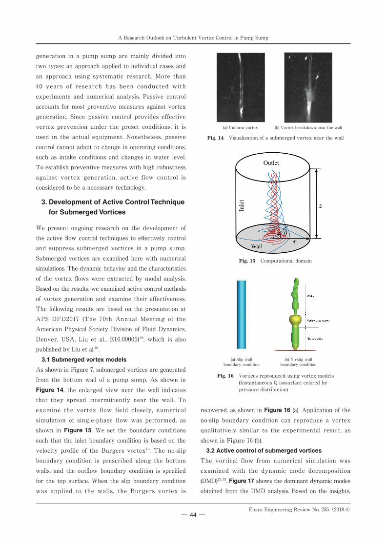
As shown in Figure 7, submerged vortices are generated from the bottom wall of a pump sump. As shown in Figure 14, the enlarged view near the wall indicates that they spread intermittently near the wall. To examine the vortex flow field closely, numerical simulation of single-phase flow was performed, as shown in Figure 15. We set the boundary conditions such that the inlet boundary condition is based on the velocity profile of the Burgers vortex21). The no-slip boundary condition is prescribed along the bottom walls, and the outflow boundary condition is specified for the top surface. When the slip boundary condition was applied to the walls, the Burgers vortex is
(a) Slip wallboundary condition
(b) No-slip wallboundary condition
Fig. 16 Vortices reproduced using vortex models (Instantaneous Q isosurface colored by pressure distribution)
Fig. 15 Computational domain
(a) Uniform vortex (b) Vortex breakdown near the wall
Fig. 14 Visualization of a submerged vortex near the wall

A Research Outlook on Turbulent Vortex Control in Pump Sump
Ebara Engineering Review No. 255(2018-4)─ ─45
we hypothesize the vortex structures on the downstream side can be broken apart by providing appropriate disturbances through active flow control methods. We describe one of the effective control methods based on the actuation input listed in the Table below. Actuation weakened vortices by applying blowing and suction from the bottom wall at the center of the vortex so that the velocity profile is changed in the circumferential direction. Here, A is amplitude, ωC is angular velocity, t is time, and ± indicates the rotation direction of blowing and suction. θ, r, and, z are the circumferential direction, radial direction, and height direction in the cylindrical coordinate system, respectively. The control variables are the frequency and amplitude. The velocity profile rotates in the same direction as that of the vortex rotation (co-rotating) or in reverse (counter-rotating) around the center of the vortex.
Figure 18 shows the effect of vortex control based on the time-averaged pressure. Regardless of whether control is performed in the same rotation direction or in the reverse direction, the static pressure of the vortex center generally increased. Moreover, the static pressure gradient in the downstream direction became smooth from around the wall. Here, the ratio of the rising static pressure is calculated as Preduce = (P c
avg −Pavg) / Pavg , where Pavg is the time-averaged static pressure in the circumferential direction and c (superscript) denotes the controlled case. The ratio of increase in static pressure in the co-rotating and counter-rotating directions are about 60 % and 39 %, respectively. Figure 19 shows controlled vortices. We confirmed that vortex cores are more dispersed with the co-rotating control than with the counter-rotating one.
Table Control methods
Control strategy Co-rotating Counter-rotatingMass injection Acos(θ−ωc t)e− r2 Acos(θ+ωc t)e− r2
Fig. 17 Dominant dynamic modes of submerged vortex (colored by uz)
Fig. 18 Change in the static pressure distribution with control
(a) Counter-rotating (b) Co-rotating
Fig. 19 Vortical structures with control (Instantaneous Q-isosurface colored by pressure distribution)

A Research Outlook on Turbulent Vortex Control in Pump Sump
Ebara Engineering Review No. 255(2018-4)─ ─46
4. Conclusion
Active flow control is an effective tool for developing fluid-based machines with high efficiency and high performance. In support of the development of flow control techniques, modal analysis22)-26) and data science27), 28) based on research on the non-stationary behavior of turbulence are considered. In this paper, we consider an industrial flow example of a turbulent submerged vortex that appears in pump sumps, and review research and development activities on vortex prevention at Ebara. We also present our efforts to develop an active flow control technique based on modal analysis. As data science continues to develop in areas such as machine learning and big data processing techniques, future approaches in fluid dynamics research are expected to be chaneged. We anticipate that the fusion of fluid mechanics and data science can facilitate the characterization of turbulent flows and support the development of active turbulent flow control strategies.
References
1) Ecke, R. The turbulence problem, Los Alamos Science, 29, p.124-141, (2005).
2) Reynolds, O. On the dynamical theory of incompressible viscous fluids and the determination of the criterion, Philosophical Transactions of the Royal Society of London. A186, p.123-164, (1895).
3) Kajishima, T. “Numerical Simulation of Turbulent Flows (revised edition)” (in Japanese), Yokendo, Co. Ltd., 2014.
4) Schmitt, F. G. Turbulence from 1870 to 1920: The birth of a noun and of a concept, Comptes Rendus Mécanique, 345.9, p.620-626, (2017).
5) Thomson, W (Lord Kelvin). Stability of motion (continued from the May, June and August numbers). Broad rivers flowing down an inclined plane bed, Philos. Mag., 24.148, p.272–278, (1887).
6) Munday, P. M. and Taira, K. Effects of wall-normal and angular momentum injections in airfoil separation control, AIAA Journal, p.1-13, (2017).
7) Walsh, M. Turbulent boundary layer drag reduction using riblets, 20th Aerospace Sciences Meeting, (1982).
8) Choi, H., Moin, P. and Kim, J. Direct numerical simulation of turbulent flow over riblets, Journal of Fluid Mechanics, 255, p.503-539, (1993).
9) Rashed, M. K., et al. Effect of structure height on the drag reduction performance using rotating disk apparatus, Fluid Dynamics Research, 49.1, 015507, (2016).
10) Nishikawa, K. “Three Model Experiments of Suction pits,” Ebara Engineering Review No. 78, p.12-19, (1972).
11) Nishikawa, K., Takashima, M. and Yamada, K. “Pump Suction Sump Model Tests (Three Examples),” Ebara Engineering Review No.107, p.16-19, (1979).
12) Tagomori, M. “An Experimental Study on the Formation of Air-Entraining Vortices and Vortex Suppression Devices in a Straight Sump,” Ebara Engineering Review No.102, p.2-6, (1977).
13) Tagomori, M. “An Experimental Study on Air-Entraining Vortices and Flow Pattern in Pump Sump (1st Report),” Ebara Engineering Review No.111, p.55-59, (1980).
14) Tagomori, M. “The Flow Pattern and Air-Entraining Vortex in the Pump Sump (2nd Report: Effect of Sump Dimensions),” Ebara Engineering Review No.113, p.2-7, (1980).
15) Tagomori, M. and Tanaka, Y. “Flow-Pattern and Air-Entraining Vortex in the Pump Sump − 3rd Report: Influence of Inlet Conditions−,” Ebara Engineering Review No.116, p.2-8, (1981).
16) Tagomori, M. and Gotoh, M. “Effects of Inlet Flow Conditions in Pump Sump on Vortex Occurrence and Pump Performance,” Ebara Engineering Review No.154, p.2-7, (1992).
17) Obuchi, M. and Tagomori, M. “Water-level Fluctuation in a Pump Sump with Coupled Pit and Countermeasures against Unfavorable Vortices,” Ebara Engineering Review No.214, p.3-6, (2007).
18) Eto, F., Zhao, L., and Owada, N. “Applying of CFD Analysis to Countermeasures against Undesirable Vortices in a Pump Sump at the Reconstruction of Nukata Drainage Pump Station,” Ebara Engineering Review No.240, p.22-26, (2013).
19) Liu, Q., An, B., Nohmi, M., Obuchi, M. and Taira, K. Influence of unsteady perturbations on a wall-normal vortex, Bulletin of the American Physical Society, 62, E16.00005, (2017).
20) Liu, Q., An, B., Nohmi, M., Obuchi, M., and Taira, K., Core-Pressure Alleviation for a Wall-Normal Vortex by Active Flow Control, Journal of Fluid Mechanics, 853, R1, (2018).
21) Burgers, J. M. A mathematical model illustrating the theory of turbulence, Advances in Applied Mechanics. Vol.1. Elsevier, p.171-199, (1948).
22) Schmid, P. J. Dynamic mode decomposition of numerical and experimental data, Journal of Fluid Mechanics, 656, p.5-28, (2010).
23) Rowley, C. W. et al. Spectral analysis of nonlinear flows, Journal of Fluid Mechanics , 641, p.115-127, (2009).
24) Taira, K. et al. Modal analysis of fluid flows: an overview, AIAA Journal, 55.12, p.4013-4041, (2017).
25) Taira, K. Proper Orthogonal Decomposition in Fluid Flow Analysis: 1. Introduction, 30, p.115-123, (2011).
26) Taira, K. Proper Orthogonal Decomposition in Fluid Flow Analysis: 2. Applications, 30, p.263-271, (2011).
27) Brunton, S. L. and Noack, B. R. Closed-loop turbulence control: progress and challenges, Applied Mechanics Review, 67, 050801, (2015).
28) Nair, A. G., Brunton, S. L. and Taira, K. Networked oscillator based modeling and control of unsteady wakes, Physical Review E, 97, 063107, (2017).