a “refresher” on vswr · a “refresher” on vswr • note: if the transmission line is much...
TRANSCRIPT

A “Refresher” on VSWR
• Note: If the transmission line is much less than , then the analysis of “transmission line transformers” and possibly “baluns” is more appropriate.
λ / 4
• VSWR stands for “Voltage Standing Wave Ratio” sometimes abbreviated as just SWR.
• The subject is appropriate for all types of transmission lines.

Transferring Power in Transmission Lines
• For maximum power transfer, the impedance at the load end of the line must be matched to the transmission line’s characteristic impedance.
Z
Z
o
oL
CHARACTERISTIC IMPEDANCE =
= Z
Transmitter Tuner
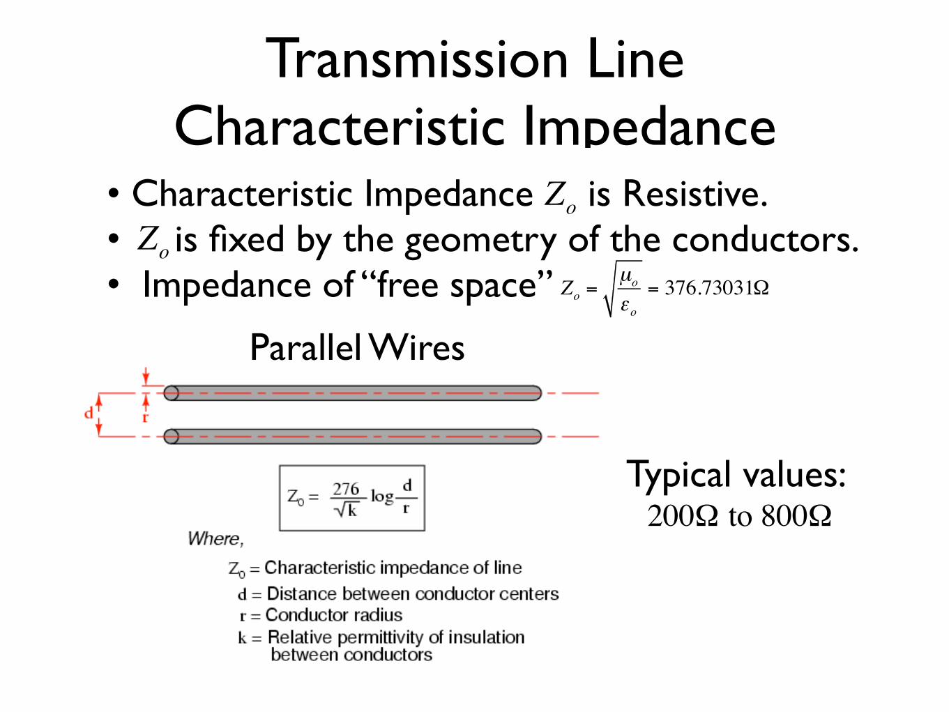
Transmission Line Characteristic Impedance
• Characteristic Impedance is Resistive. • is fixed by the geometry of the conductors. • Impedance of “free space” Zo
Zo
Zo =µo
εo= 376.73031Ω
Parallel Wires
Typical values: 200Ω to 800Ω
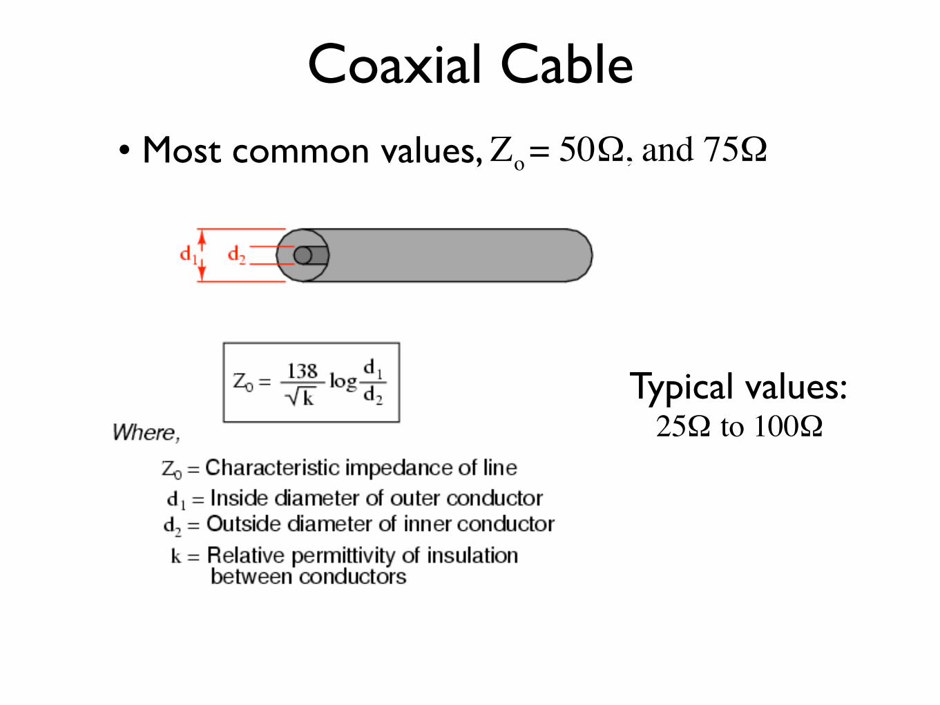
Coaxial Cable• Most common values, Zo = 50Ω, and 75Ω
Typical values:25Ω to 100Ω
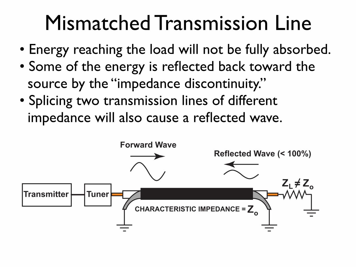
Mismatched Transmission Line• Energy reaching the load will not be fully absorbed. • Some of the energy is reflected back toward the source by the “impedance discontinuity.” • Splicing two transmission lines of different impedance will also cause a reflected wave.
Z
Z
o
ZoL
CHARACTERISTIC IMPEDANCE =
=
Forward Wave
Reflected Wave (< 100%)
Transmitter Tuner
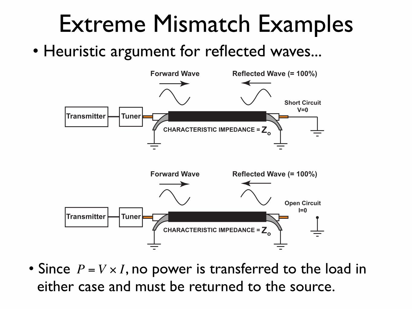
Extreme Mismatch Examples
• Since , no power is transferred to the load in either case and must be returned to the source.
P =V × I
• Heuristic argument for reflected waves...
ZoCHARACTERISTIC IMPEDANCE =
Forward Wave
Transmitter Tuner
Reflected Wave (= 100%)
Short CircuitV=0
ZoCHARACTERISTIC IMPEDANCE =
Forward Wave Reflected Wave (= 100%)
Open CircuitI=0
Transmitter Tuner

OK, Now the Math• In a mismatched transmission line, the ratio of the voltage in the reflected wave at any one point to the forward wave at the same point is defined as the “voltage reflection coefficient,” (rho).ρ
ρ =ZL − Zo
ZL + Zo
• In principle, this is a “complex” number if we consider reactive loads, but for the moment, we will only consider resistive loads with “real” reflection coefficients.

Some Examples• First the feedpoint impedance of a resonant Dipole antenna in “free space” is .ZL = 73Ω
• The feedpoint impedance of a 14 MHz Ground Plane antenna at 15 m above ground is .
ZL = 26 − j3.2Ω ≅ 26Ω
ρ =73− 5073+ 50
=23123
= 0.187
ρ =26 − 5026 + 50
=−2476
= −0.316

VSWR• The VSWR is:
VSWR =1+ ρ1− ρ
• For the resonant Dipole in free space:
VSWR = 1+ 0.1871− 0.187
=1.1870.813
= 1.46
• For the 14 MHz Ground Plane:
VSWR = 1+ 0.3161− 0.316
=1.3160.684
= 1.92

Forward Wave, Length=1λ

Reverse Wave, ρ=-0.3
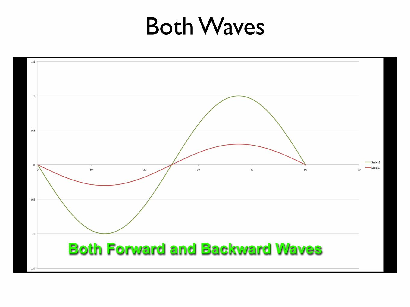
Both Waves

Now, Sum Both Waves
VSWR = 1.30.7
= 1.86

Formula Variations• The Voltage Reflection Coefficient can be calculated from Forward & Reverse Powers.
ρ =PRPF
• Sometimes “Return Loss” is calculated:
RL(dB) = 10 log10PFPR
!
"#
$
%& = 10 log10
1ρ2
RL(dB)= −20 log10 ρ
• For example:
ZL = 75Ω Zo = 50Ω ρ = 0.2 VSWR = 1.5 PR
PF
= 0.04 RL = 14 dB
Note: Return Loss is often used when the VSWR is close to 1.0
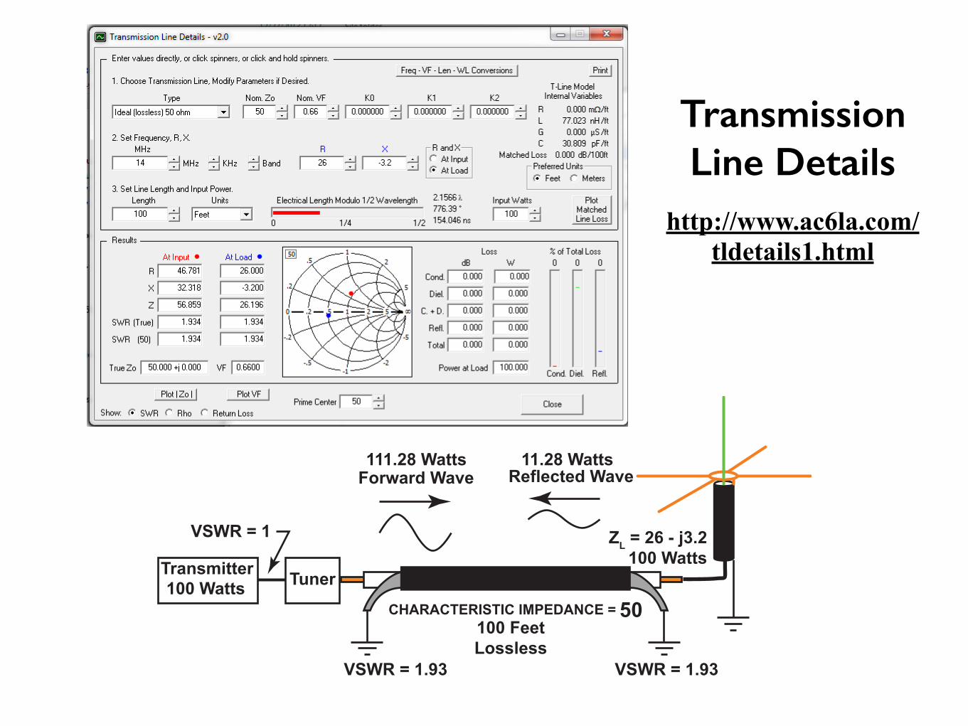
50CHARACTERISTIC IMPEDANCE =
Forward Wave
VSWR = 1
100 Watts
111.28 Watts 11.28 Watts
Reflected Wave
VSWR = 1.93VSWR = 1.93
100 Feet
Lossless
ZL = 26 - j3.2
100 WattsTransmitter
Tuner
http://www.ac6la.com/tldetails1.html
Transmission Line Details

50CHARACTERISTIC IMPEDANCE =
Forward Wave
VSWR = 1
100 Watts
111.28 Watts 11.28 Watts
Reflected Wave
VSWR = 1.93VSWR = 1.93
100 Feet
Lossless
ZL = 26 - j3.2
100 WattsTransmitter
Tuner
The antenna tuner adjusts the electrical length of the antenna and coax so that the reflected energy (11.28 Watts) has exactly the correct phase to be re-reflected at the antenna tuner. When the tuner is correctly tuned, no energy gets back into the transmitter.
Backward Traveling Wave is Re-Reflected at the Tuner
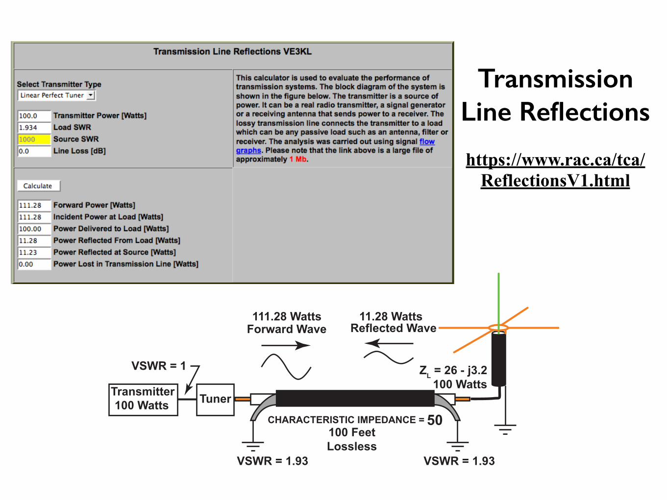
50CHARACTERISTIC IMPEDANCE =
Forward Wave
VSWR = 1
100 Watts
111.28 Watts 11.28 Watts
Reflected Wave
VSWR = 1.93VSWR = 1.93
100 Feet
Lossless
ZL = 26 - j3.2
100 WattsTransmitter
Tuner
https://www.rac.ca/tca/ReflectionsV1.html
Transmission Line Reflections
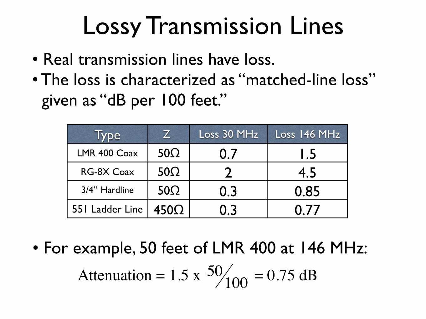
Lossy Transmission Lines• Real transmission lines have loss. • The loss is characterized as “matched-line loss” given as “dB per 100 feet.”
Type Z Loss 30 MHz Loss 146 MHz
LMR 400 Coax 50Ω 0.7 1.5RG-8X Coax 50Ω 2 4.53/4” Hardline 50Ω 0.3 0.85
551 Ladder Line 450Ω 0.3 0.77
• For example, 50 feet of LMR 400 at 146 MHz:
Attenuation = 1.5 x 50100 = 0.75 dB
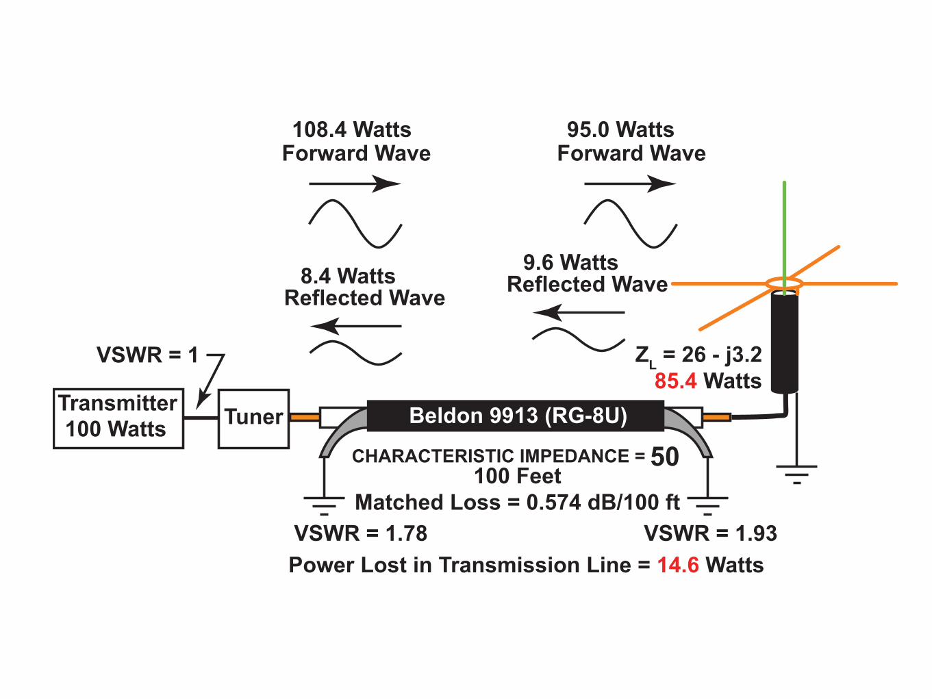
50CHARACTERISTIC IMPEDANCE =
Forward Wave
VSWR = 1
100 Watts
108.4 Watts
Forward Wave
95.0 Watts
9.6 Watts
Reflected Wave8.4 Watts
Reflected Wave
VSWR = 1.93VSWR = 1.78
Beldon 9913 (RG-8U)
100 Feet
Matched Loss = 0.574 dB/100 ft
ZL = 26 - j3.2
85.4 Watts
Power Lost in Transmission Line = 14.6 Watts
TransmitterTuner
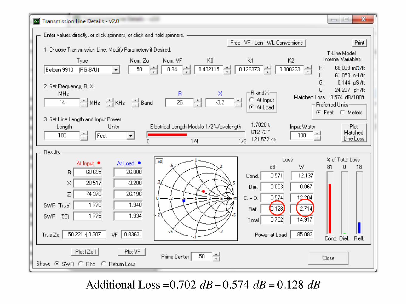
Additional Loss =0.702 dB−0.574 dB = 0.128 dB

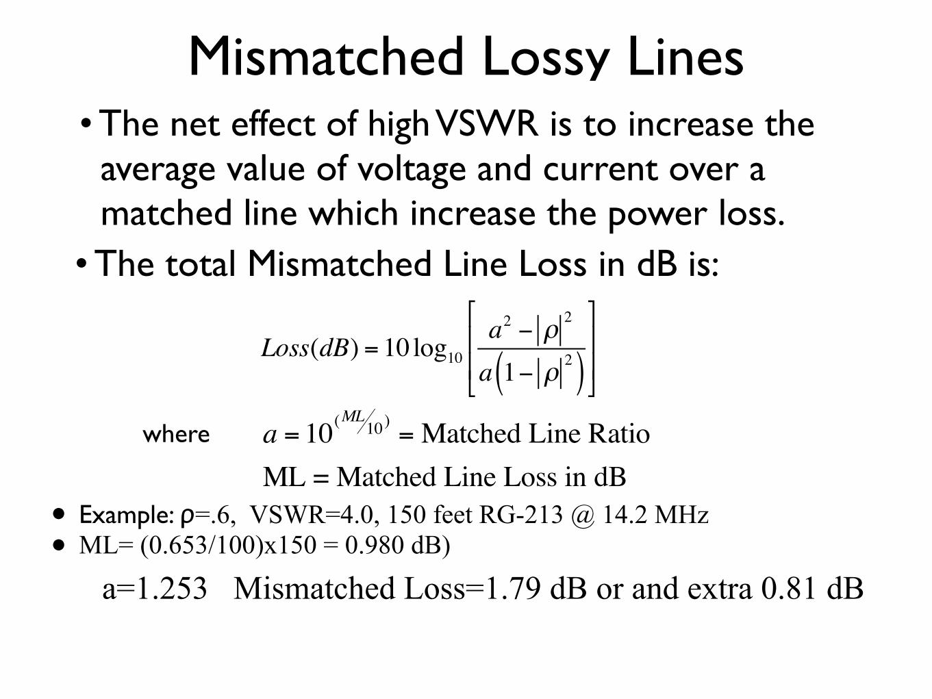
Mismatched Lossy Lines• The net effect of high VSWR is to increase the average value of voltage and current over a matched line which increase the power loss.• The total Mismatched Line Loss in dB is:
Loss(dB) = 10 log10a2 − ρ
2
a 1− ρ2( )
#
$
%%
&
'
((
where a = 10(ML10)= Matched Line Ratio
ML = Matched Line Loss in dB• Example: ρ=.6, VSWR=4.0, 150 feet RG-213 @ 14.2 MHz • ML= (0.653/100)x150 = 0.980 dB)
a=1.253 Mismatched Loss=1.79 dB or and extra 0.81 dB
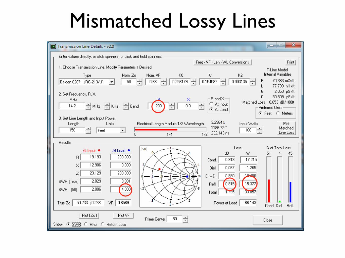
Mismatched Lossy Lines
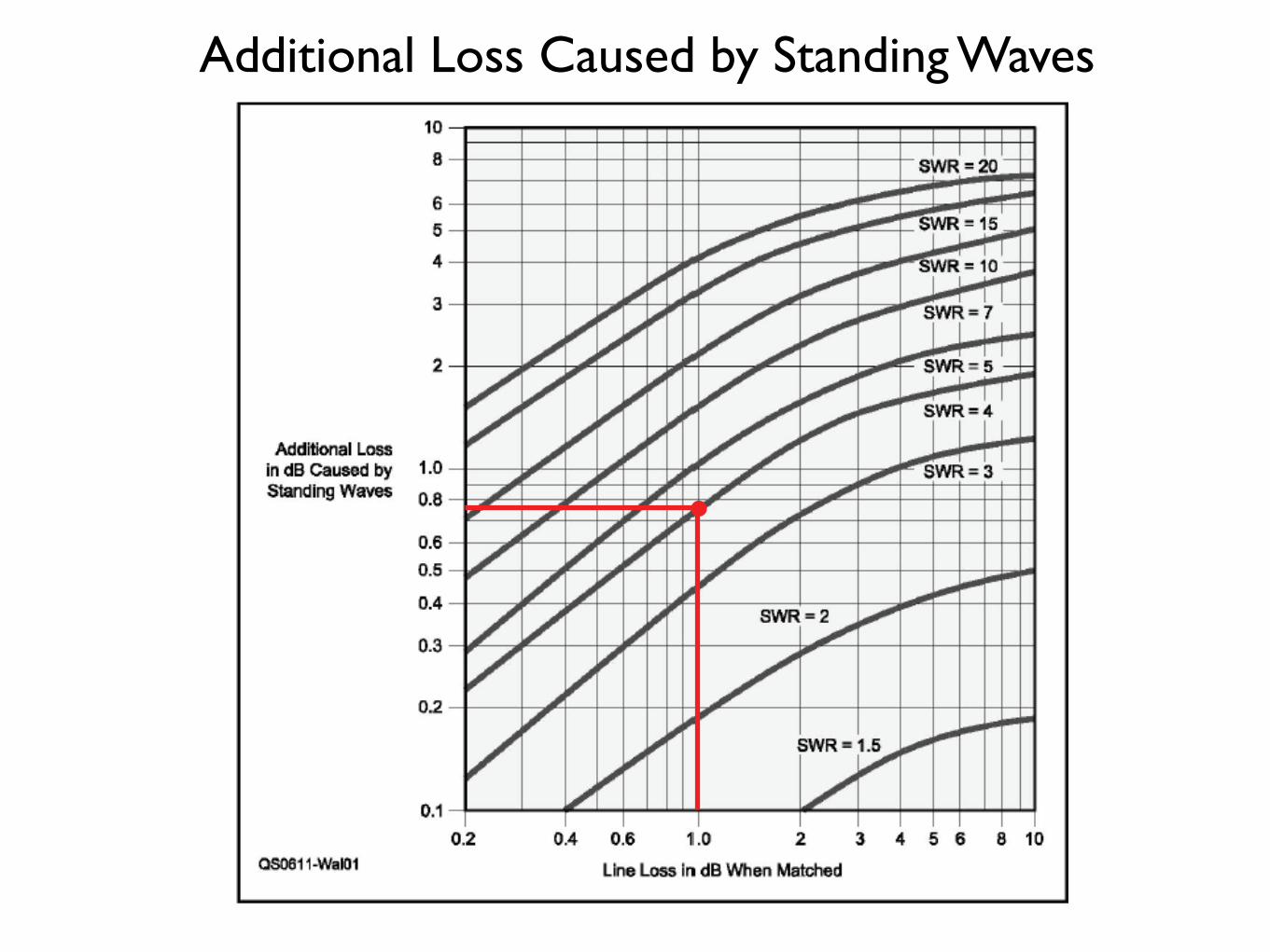
Additional Loss Caused by Standing Waves
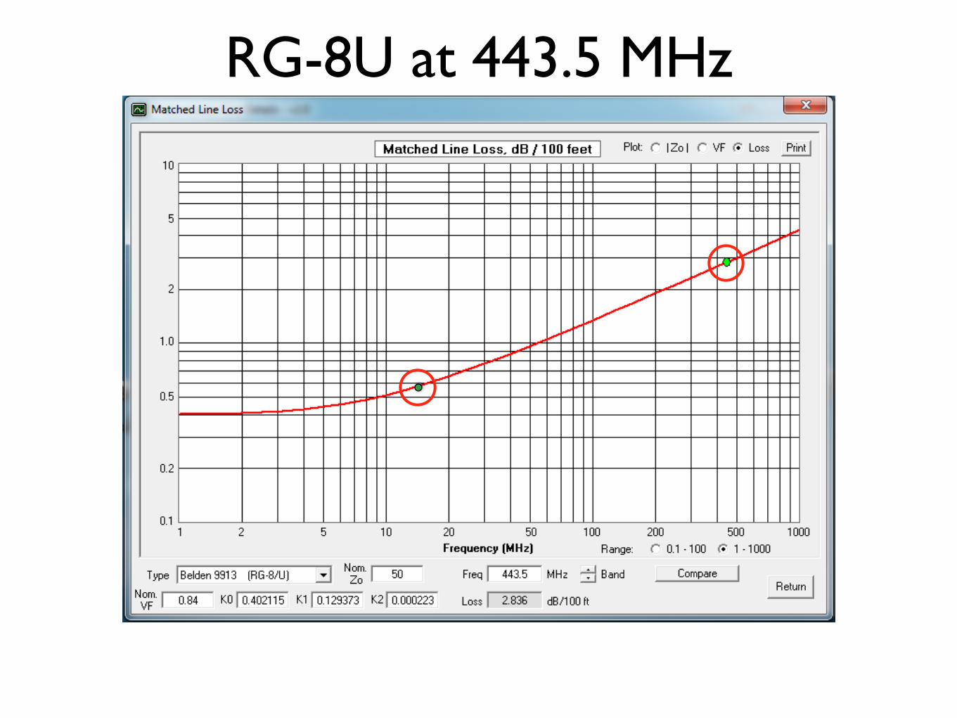
RG-8U at 443.5 MHz
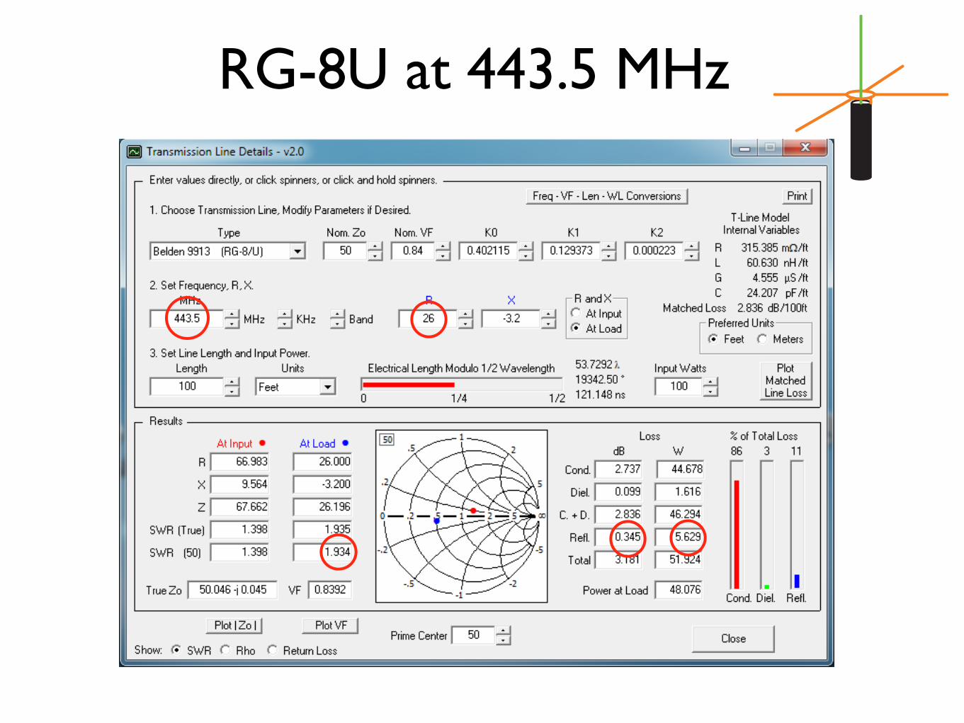
RG-8U at 443.5 MHz
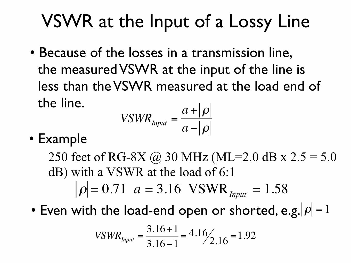
VSWR at the Input of a Lossy Line
• Because of the losses in a transmission line, the measured VSWR at the input of the line is less than the VSWR measured at the load end of the line.
VSWRInput =a + ρa − ρ
• Example250 feet of RG-8X @ 30 MHz (ML=2.0 dB x 2.5 = 5.0 dB) with a VSWR at the load of 6:1
ρ = 0.71 a = 3.16 VSWR Input = 1.58• Even with the load-end open or shorted, e.g. ρ = 1
VSWRInput =3.16+13.16−1
= 4.16 2.16 =1.92

Now you can explain everything about your antennas!
Here is a good article to help: http://www.hamuniverse.com/wc7iswr.html