a receptionist robot: interaction and coordination
TRANSCRIPT
1
A Receptionist Robot: Interaction andCoordination
Manuel Jose B. C. Malhado
Institute for Systems and Robotics
Instituto Superior Tecnico
Abstract—This article presents a project that consists onthe development of a receptionist robot for the Institutefor Systems and Robotics (ISR), Lisbon. This robot is sta-tioned at ISR’s 6th floor elevator lobby where it waits forapproaching visitors. At this point it attempts to interactwith them in order to find out whether the they wish to belead to a specific room on this floor.
The followed development methodology focuses on theintegration of several modules, featuring navigation and lo-calization capabilities, a graphical interface, speech recog-nition and synthesis, people detection, face detection, andbehavior control, in order to achieve an autonomous sys-tem. In order to save time and effort, as well as obtaining arobust solution, “off-the-shelf” software packages are usedwhenever possible.
This project was divided in two sub-projects. The presentone focuses, apart from the conception of the robot’s hard-ware and software architecture design, on its human-robotinteraction capabilities, as well as on all robot modules’ in-tegration and coordination.
Experimental results obtained in order to evaluate theemployed speech recognition engine robustness and the in-tegrated system overall performance, are also presented inthis article.
This project autonomous robot development process isdescribed in much more detail in this thesis [1], specially inthe areas focused by this article.
Index Terms—Receptionist robot, human-robot interac-tion, graphical interface, speech recognition, behavior con-trol.
I. Introduction
AUTONOMOUS robotics is a research field which hasbeen in development since the middle of the 20th cen-
tury and it is currently one of the main areas of interestwithin the field of Robotics. Even though great break-throughs have been achieved throughout the years, thisarea still has a long way to go, as much in terms of sen-sory, mechanical, and mobility capabilities as well as in theartificial intelligence and decision making domain, beforeit can achieve efficient and flexible behaviors comparableto the ones observed in animals and humans.
Current real life applications using robot agents are rel-atively scarce and usually restricted to particular areas(such as industry and space exploration) where the useof human labor is not possible or is inconvenient, eitherbecause the task at hand is life threatening or inaccessibleto human beings.
A common requirement for the environment where therobot shall operate, is that it has to be relatively pre-dictable, since current robot agents’ capacity to adapt tonew and unexpected situations is still very limited. Thisfact is a major reason why there are still so few success-ful initiatives that use robotic agents to assist and interact
with regular people, since these can be extremely unpre-dictable and different from each other.
People’s unpredictability is very much related with thedifferent reactions they can express towards an unusual andunknown identity such as an automaton. For this reason,today’s key for developing a successful people interactingagent might not be employing an extremely complex de-cision system that seeks to cover all possible situations,but rather to use a human being’s almost unlimited selfadaptive capacity to adjust itself to the robot platform.This can be achieved by providing, on the one hand, themeans to help them feel comfortable with the whole situ-ation, and on the other hand, to guide them through theprocess of interaction by initially taking the initiative tostart a “conversation”/communication, and then directingand narrowing it through an expected line of reasoning.In order to make a person feel more at ease while inter-acting with the robot agent, besides presenting an intu-itive and enjoyable interface, the automaton might featurehuman/animal like characteristics, with whom people areaccustomed to deal with.
The current project falls under the mentioned field ofapplications, consisting on the development of a demon-stration robot targeting an audience of people who mani-fest a certain curiosity for the field of robotics. The robotshould behave as a receptionist that socially interacts withapproaching people, being capable of guiding them to on-the-spot requested locations within a known environment.Adequate dimensions and hardware support are requiredfeatures for the robot to navigate around the intended en-vironment and to interact/communicate with people usingspeech and visual interfaces (some hardware was readilyavailable from previous projects, but extra devices had tobe acquired).
The desired robotic agent requires several specific capa-bilities, covering a set of different fields of research anddevelopment. Since various promising initiatives (whichmay or may not have been originally designed to be im-plemented on a robotic platform) capable of solving par-ticular robot requirements are available as commercial oropen-source software packages, it is of this project’s in-terest to find the most robust and powerful solutions andadapt them to the proposed goals.
The Receptionist’s development process consisted of sev-eral individual steps, starting with the research for featuredcapabilities on similar initiatives, followed by the concep-tion of the robot’s software and hardware architectures,the implementation and testing of individual modules, and
2
finally the progressive integration of each developed sub-system into a fully working system. This project’s workwas divided into two separate theses which shared thetasks of research and conception, but from that point on-ward different responsibilities were assigned to each other.This thesis is responsible for the development of all theRobot’s human-robot interaction capabilities, as well asfor the implementation of the receptionist’s behavior andintegration of all system’s individual parts. The compan-ion sub-project [2] is devoted to the implementation of anavigation and localization solution, capable of fulfillingthe requirements set, and to handle all Robot image pro-cessing, necessary to implement people and face detectionfunctionalities.
II. Context Scenario
The Receptionist robot is stationed in the elevatorslobby of ISR’s 6st floor, waiting for a person to approachit. Upon detection of their presence, the robot approachesthe person, facing them, and then it starts dialog interac-tion by introducing itself and offering its services. If theperson shows interest, by acknowledging the robots intro-ductory intervention, the receptionist inquires about theroom/location the person would like to be guided to, andsubsequently it starts to move towards the destination in-dicated by the person. Upon arrival to the requested desti-nation, the receptionist announces the arrival and inquireswhether further assistance is needed. If the person showsto be already satisfied with its help, the robot returns to itsstarting position, where it awaits for the arrival of anotherperson.
III. System Architecture
Considering the problem at hand, it was decided thata modular architecture would be the most fitting. Thisarchitecture is very flexible, permitting the segmentationof the development process (design, implementation andtesting) into separate and somewhat independent modules(since the work effort is divided into two different theses,each of them is responsible for the development of spe-cific modules), and easing the task of future developmentby allowing the replacement of specific modules and intro-duction of new ones without the need to alter the entiresystem.
The modules which are fully covered by this thesis (i.e.,Coordination, Speech Synthesis and On-Screen Interface,and Speech Recognition), are described in detail in thefollowing sections.
A. Coordination
Responsible for the top level system coordination be-tween modules, it controls all the receptionist robot’s reac-tions to external stimuli, ultimately resulting in the robot’soverall behavior.
This module runs over a hierarchical finite state ma-chine, implemented using the UML StateWisard toolkit
framework1.
B. Navigation and Localization
As its name implies, this module covers all the robot’snavigation and localization requirements.
This module is implemented over Carnagie Mellon Nav-igation toolkit (CARMEN)[3], an open source softwarepackage for mobile robot control which performs the re-ferred tasks, using the data provided by the receptionist’slaser sensor and odometry board, and a previously gener-ated map.
A detailed description of this module can be found in[2].
C. On-Screen Interface and Speech Synthesis
A graphical interface was developed with the use ofwxWidgets [4], a Cross-Platform GUI programing toolkit,and Xface [5], a toolkit for the creation of embodied con-versational agents. It has several GUI elements that canbe accessed through the touch-screen, and it is responsiblefor all non-voiced interaction with the user.
Speech synthesis is also this module’s responsibility,and it is performed by Microsoft’s Speech ApplicationProgramming Interface (SAPI)2, which is incorporated inXface for lip-synchronization purposes.
For a more detailed description on this module, refer tosection VII.
D. Speech Recognition
By use of a set of different predefined grammars (with alimited lexicon), which are employed according to the cur-rent context of operation, speech recognition is performedthrough Microsoft’s SAPI SDK.
For a full description of this module, refer to section V.
E. Face Detection
For the robot to be able to maintain eye contact with theuser, an algorithm that performs face detection is required.Thus, OpenCV’s [6] face detection algorithm is used as abase for the development of this module.
A more detailed description of this module can be foundin [2].
F. People Detection
Omni-directional vision systems are not commonly usedfor the task at hand, hence no readily available algorithmhas been found for this purpose and one had to be devel-oped from scratch. In a general way, this algorithm startsby performing motion detection (through background sub-traction) and, by analysis of the image region where move-ment was detected, it evaluates the region’s geometry bymatching it to the geometry features of a person’s legs andfeet.
OpenCV’s libraries are widely used for this module’s im-age processing necessities.
1 http://www.intelliwizard.com/ (last retrieved in 09/2008)2 http://www.microsoft.com/speech/speech2007/default.mspx
(last retrieved in 09/2008)
Manuel Malhado: A RECEPTIONIST ROBOT: INTERACTION AND COORDINATION 3
This module is fully discussed in [2].
G. YARP (inter module/device communication)
The middleware, especially designed for robots, usedin this project is known as Yet Another Robot Platform(YARP) [7], and consists of a set of open-source libraries,protocols, and tools which are able to perform communi-cation between different software modules and hardwaredevices in a decoupled and accessible way.
YARP is designed to be operating system independent,and allows communication between modules/devices thatcoexist in the same computer (using the operating system’sshared memory) or that are running in different machineson an IP network, through the use of carrier protocols likeUDP (for data streaming), TCP (for data that absolutelyneeds to arrive to the destination, like commands) andmulti-cast.
IV. Physical Platform
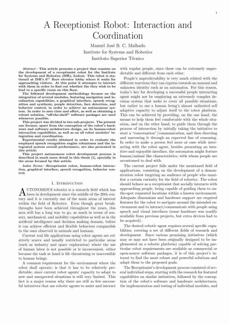
Fig. 1. Virtual representation of the Receptionist robot
The robotic platform adopted for the Receptionist robotconsists of a modified version of a Nomatic SuperScout II[8], a commercial unicycle robot. This platform holds aset of devices that offer suitable hardware support, suchas a Pentium 3 computer running on Linux, wheels mo-tor controllers, odometry board, and an omni-directionalvision system. However, several additional devices had tobe acquired in order for the robot to perform as intended:A Flybook v33i tablet PC featuring a touch-screen andrunning on Windows XP; a Philips ToUcam Pro webcam,used for face detection; a Labtec PC Mic 333 microphone;and an Hokuyo-URG-04LX laser range finder.
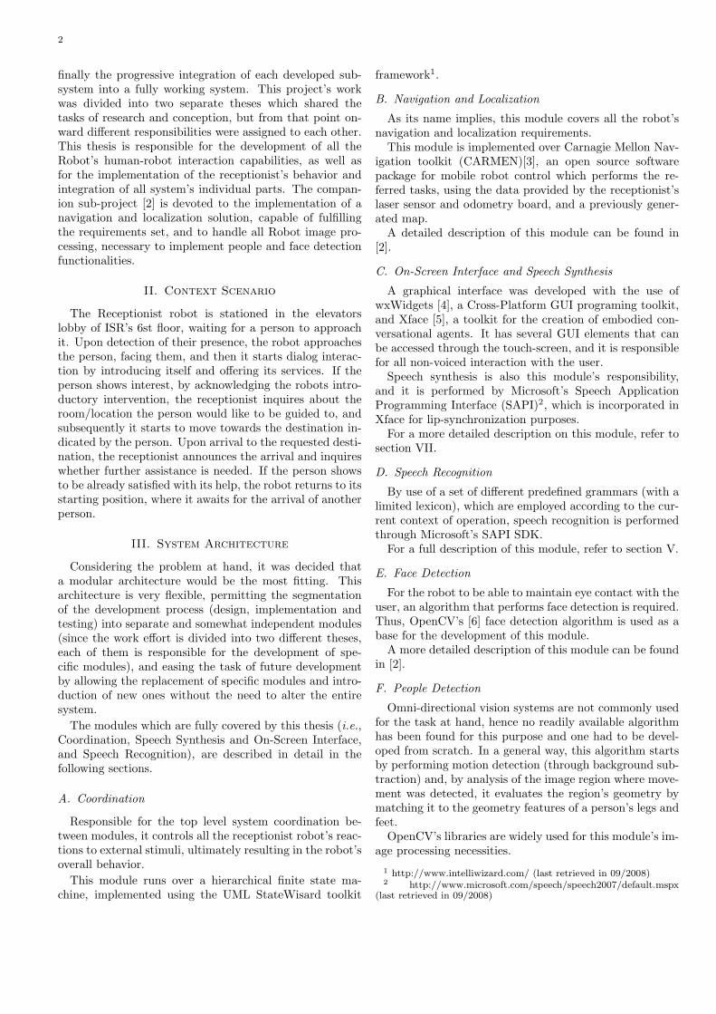
In Figure 2 a representation of the system architecture,from a physical point of view, is presented: The gray andred rectangles represent the computers running on Linuxand Windows XP, respectively; the light blue boxes arethe systems modules, which are implemented in either ofthe available computers; the dashed bordered boxes rep-resent hardware devices (the ones in red bordered boxesare built-in to the Windows XP computer); the black andorange arrows represent the data flow of communicationbetween modules/devices either supported by built-in orYARP connections, respectively; the dashed arrows repre-sent connections over an IP network; the blue arrow rep-resents a regular TCP Ethernet connection using sockets,
and the yellow boxes represent the processes that imple-ment the Linux Monitor, used for the Linux computer con-trol through the tablet PC.
Fig. 2. Hardware Architecture
V. Speech Recognition
This module is responsible for recognizing speech se-quences within an expected limited set of context depen-dent sentences, uttered by any person that the ReceptionistRobot might interact with (expectantly, fully grown adultswith good knowledge of the English language).
A. SAPI SDK 5.1 speech recognition software
SAPI SDK 5.1 was chosen as the speech recognitiontoolkit that would implement this module’s speech neces-sities. This software is application development oriented,providing easy-to-use interfaces to develop Windows ap-plications with speech recognition support. It intends tomask all the complexity associated with the task of speechrecognition, providing an already trained, speaker indepen-dent, and mature speech recognition engine.
SAPI can use Finite State Grammars as language mod-els, which are configured through XML grammar files.These grammars permit the definition of the phrases theengine is able to recognize, through a sequence of wordscontained in tags that define: if that set of words has to beexpressed at that particular point of the sentence; if oneof the set of words in a group is expected at that point;or if a set of words is optional (i.e., this set of words mayor may not be uttered by the speaker; the recognizer willreckon the rest of the sentence either way). XML grammarfiles syntax and lexicon is fully described in SAPI’s helpdocumentation.
In order for an application to be able to deal with newrecognition data, SAPI generates a Windows event thatincludes useful information concerning the recognition re-sult. This includes, but it is not restricted to:

4
• The recognition’s successfulness, which can be oneof three values: successful recognition, unsuccessfulrecognition, and interference detected;
• The kind of interference that was detected, if per-ceived. It can be one of the following: no signal, noise,too loud, too quiet, too fast, or too slow;
• The index of the recognized output;• The exact sentence that the recognizer believes it was
uttered;• The confidence level of the recognition, which can be
one of three values: hight, normal and low;
B. Speech Recognition Control
This module has two possible states of operation: it iseither waiting for control commands, or waiting for newsound input, in order to perform a recognition. In figure3, a Mealy finite state machine [9] representation of thismodule is presented.
Fig. 3. Finite state machine representation of the Speech RecognitionModule. Transitions are represented in an event/action manner
VI. Experimental Results
In order to evaluate SAPI’s recognition robustness, a setof experiments using 6 different speakers were performed.It was asked each speaker to utter the same sequence ofsentences in two different scenario, each with a specificgoal:
1. This scenario’s aim is to be as close as possible tothis modules intended context of operation, in orderto evaluate its robustness in realistic conditions. Thehardware configuration that is used is the one avail-able in the Receptionist platform (the tablet PC’ssound card is used to acquire the sound captured bythe on board microphone), and the speakers whereasked to speak while standing up and about one me-ter behind the Robot;
2. This scenario is defined as a reference to understandhow much of the recognition performance is condi-tioned by the Receptionist’s context of operation. Todo so, a different (less noisy) hardware configura-tion was employed, using a SilverCrest Bass VibrationHeadset and a Toshiba Tecra A3X laptop’s sound cardfor data acquisition.
Two different language models are used during the Re-ceptionists regular operation, one to capture a positive ornegative response from the user, and the other to discern
to which room the user would like to be guided to. Consid-ering that these grammars feature rather different charac-teristics, since one of them only has two possible outcomesand short recognizable sentences, and the second is con-sidered more challenging for featuring 25 different possibleoutcomes and considerably longer recognizable sentences,their recognition performance is evaluated separately andthree different sentences to be spoken by the test subjectsare defined for each language model.
In the model defined by yes no.xml case, the sentences(in this case, words) to be spoken by the speakers are“yes”, “no”, and “maybe”. While the first two representthe shortest possible recognizable sentences and cover bothpossible recognition outcomes, “maybe” is not included inthe set of recognizable sentences and is used to evaluatehow well the recognizer handles sentences that are not sup-posed to be recognized. Since it would be impractical toevaluate all 25 destination rooms.xml model’s possiblerecognition outcomes, two random outcomes where cho-sen for evaluation: one is represented with a standard sizesentence – “Guide me to room six oh seven” – and theother features the longest recognizable sentence supportedby this grammar – “Could you please show me the way tothe Evolutive Systems and Biomedical Engineering Lab”– and possibly the most challenging to recognize. Thismodel’s defined third sentence is “lead me to nowhere”,and has the same purpose as the “maybe” utterance in theprevious grammar.
In figure 4 the obtained recognition results for each sen-tence is presented, for both the realistic and reference sce-narios.
Fig. 4. Speech Recognition results obtained in the realistic (on top)and reference (on bottom) scenarios. The variables represented inthe x axis represent each of the test sentences: S1 – “yes”; S2 – “no”;S3 – “maybe”; S4 – “take me to room six oh seven”; S5 – “Couldyou please show me the way to the Evolutive Systems and BiomedicalEngineering Lab”; S6 – “lead me to nowhere”
By analysis of both scenario results it can be concludedthat this module’s recognition performance is clearly af-fected by speech capturing conditions. In the referenceconditions scenario case, the recognition rate was of 100%
Manuel Malhado: A RECEPTIONIST ROBOT: INTERACTION AND COORDINATION 5
for all users except one, a result that is distinctly differentfrom the one obtained in the realistic scenario, where therecognition rate is drasticaly lower, expecialy in the S4 andS5 sentences case. As for the S3 and S6 sentences, the rec-ognizer clearly has trouble distinguishing a sentence thatis not covered by the grammar as unrecognized, this situ-ation is clear in both scenarios, where these results cannotbe conclusively compared since they are inconsistent andthe number of test samples is relatively small.
VII. On-screen Interface and Speech Syntheses
For the user to be able to communicate with the Recep-tionist in a non-verbal way, it was necessary to developa graphical interface, which is displayed and interactedthrough the tablet PC screen.
As a way of disseminating the interest for science andtechnology, one of the key aspects of the interface is thatit should present as much information as possible regard-ing the sensors and mechanisms that condition the Robot’sbehavior. It is also imperative, for demonstration pur-poses that the interface features the necessary controls toperform direct commands (e.g., choosing a destination bymanually selecting a room).
In order to attain an interface accessible to as manypeople as possible, an effort was made in developing aninterface that respects general usability principles like theones defined by Jakob Nielsen [10], as well as the interfacedesign principles presented by Bruce Tognazzini3(both au-thors are software consultants specialized in user interfaceusability).
The GUI programming toolkit wxWidgets [4] was em-ployed in this module’s development.
A. Interface Layout
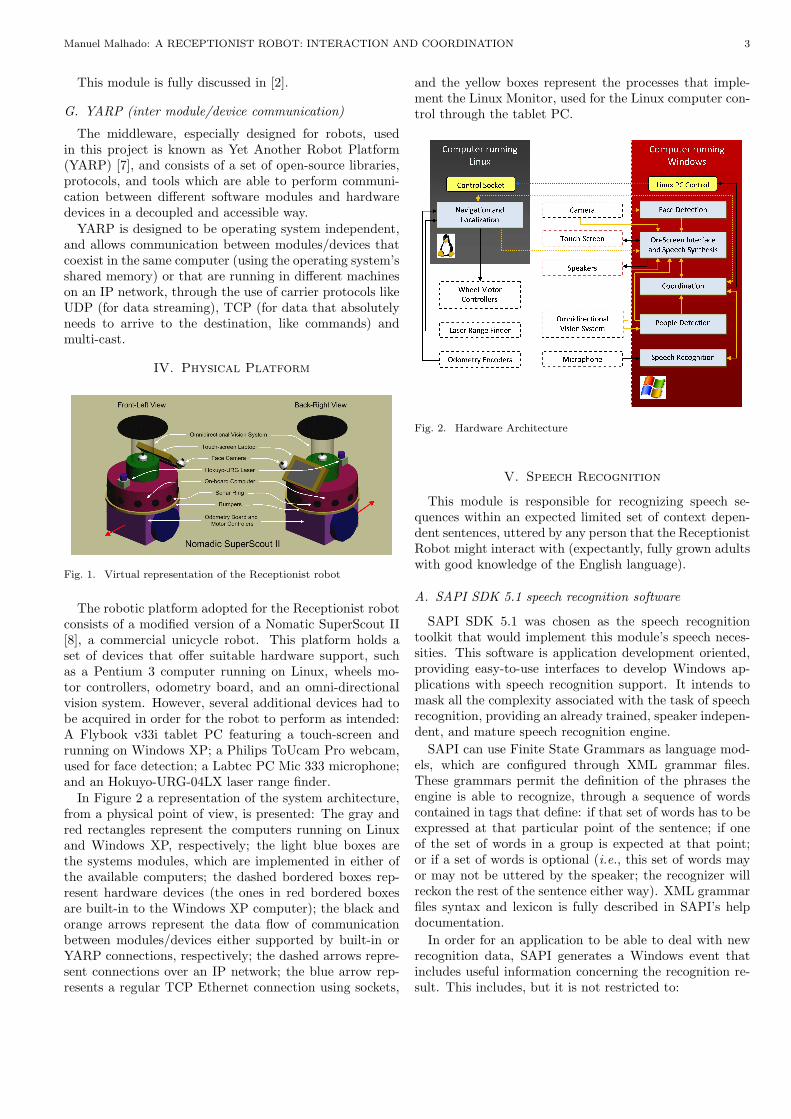
The Interface consists of two equally sized notebook win-dows (a type of window that features a set of selectabletabs), placed side by side, completely filling the screen en-vironment (figure 5). These notebooks feature the samecombination of tabs (implying the duplication of each cor-responding panel), except for the “Face” panel (describedin section B) which is only presented in the notebook onthe left, since all the animation and voice handling mecha-nism responsible for the face control is implemented in thiswindow’s class.
At the system startup, the default combination of dis-played panels is the one presented in figure 5, since theseare sufficient for the Receptionist to fully operate in Au-tonomous mode (which is described in section VIII), andare considered more inexperienced user-oriented.
B. Face Panel
In order for the Robot to present suitable human-robotinteraction, it was determined that it would require an an-imated virtual face, integrated in the graphical interface,capable of expressing emotions (this way the Receptionist
3 http://www.asktog.com/basics/firstPrinciples.html (last re-trieved in 09/2008)
Fig. 5. Graphical interface at startup. In the left – the “Face” panel;in the right – the “Dialog” panel
would be able to, for instance, express joy or sadness, de-pending on whether a requested task had been performedsuccessfully or not).
Xface [5] was the toolkit employed to implement thisvirtual face (figure 5). This software integrates MicrosoftSAPI 5.1 in order to perform speech synthesis while si-multaneously synchronizing the face’s lips according to thespoken phonemes.
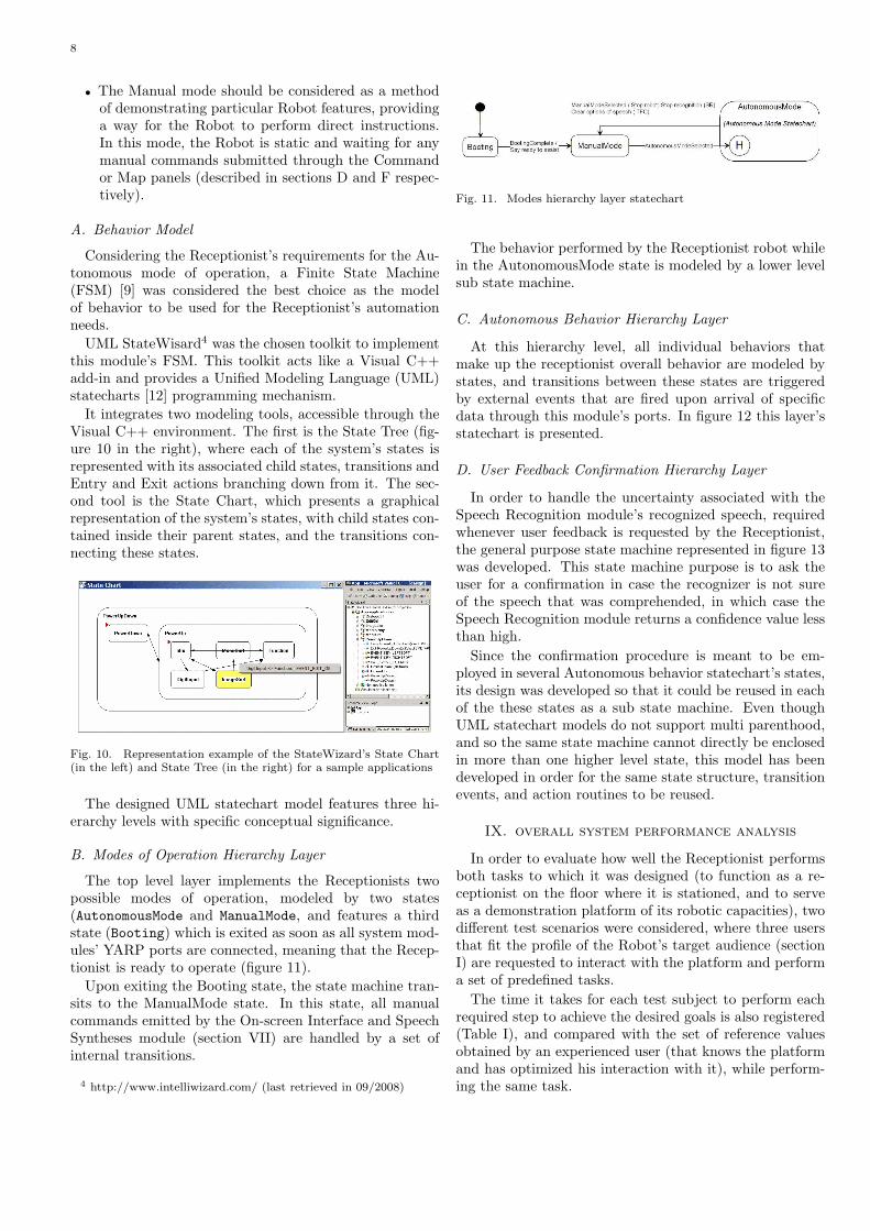
To ensure a better human/robot interaction the Recep-tionist’s face should be able to maintain eye contact withthe user, using input data from the Face Detection mod-ule. Unfortunately this is not possible since, as studied andconcluded in [11], visual perception of images representedin a planar surfaces (in this case the tablet PC screen) re-mains largely unchanged regardless of the vantage point,resulting in the impression that, if the face looks straightahead, it will seem it is looking straight at the viewer,independently of their position relative to the screen (forinstance, Da Vinci’s Mona Lisa seems to be looking di-rectly at us, regardless of the point of view from which weview the painting). The opposite is also true: if the face islooking anywhere else, the viewer will always feel the faceis looking elsewhere. Considering this last statement, theaim of rotating the virtual head in a reactive way accordingto the user face position is to give the impression that theReceptionist is paying attention to them, inviting them tofurther interact with the Robot.
In figure 6, an example of the face rotation process ispresented, consisting of two rotations of the virtual headmodel around its center. In this figure’s top left corner,a frame captured by the Robot’s camera that correspondsto the Receptionist face’s point-of-view is presented. Con-sidering the represented referential, the face primarily per-forms a rotation around the Y axis, followed by a rotationaround a vector (dependent on the first rotation) in the XZplane. The rotation angles are calculated using the user’sface position and manually adjusted coefficients.
To avoid that the Receptionist’s face instantly “looks”at a detected face when, in the previous instant, it wasfacing the other way, a discrete low pass filter is employed,resulting in smoother and realistic head movements. Thisfilter is employed by use of 1, where ’c’ is a gain that has
6
been hand adjusted to the value of 0.5.
{
NewPosX = c×UserPosX +(1− c)×LastPosX
NewPosY = c×UserPosY +(1− c)×LastPosY
(1)
C. Dialog Panel
This panel is represented in figure 5, and it features thefollowing components:
• A text control window where a log of the conversationbetween the user and the Receptionist is maintained.Red text represents the Receptionist speech (in thebeginning of each sentence, the emotion expressed bythe Receptionist’s face while speaking it is presentedbetween brackets), and the blue text represents theuser’s speech lines. This window might be useful incase the user fails to hear/understand what the Robotsays.
• A list box where the user’s currently available op-tions of speech are presented, serving as an alterna-tive means of communication with the Receptionist,as well as a reference to what the user can say thatwill be recognized.
• A button labeled “Submit Answer”, which posts thecurrently selected option in the list box;
• A check box labeled “Use Speech Recognition” is usedto activate or deactivate speech recognition.
D. Command Panel
All available buttons on this panel (figure 7), activatethe Receptionist’s Manual operation mode, except the but-ton labeled “Resume Autonomous Mode” which triggersthe Autonomous operation mode (see section VIII for thedefinition of both these modes). The remaining buttonsperform as follows:
• “Room” and “Person” buttons – Both trigger a pop-up list that features the available rooms and persons,respectively, which the user can select as a destination;
• “Base” button – Instructs the Robot to go to it is de-fault location where it waits for a person to approach,while in Autonomous mode;
• “(Pinpoint)” button – Switches to the Map Panel tab(section F), and activates its “Pinpoint Destination”button;
Fig. 6. Illustration on how eye contact with the user is performedthrough two rotations of the Receptionist’s head model around itscenter.
• “Pause”/“Continue” button – If pressed while its la-bel is “Pause” the Receptionist interrupts its currentroute, while if the button’s label is “Continue” theRobot proceeds to the last defined destination. Thisbutton is generally larger than the others in order tomake it more accessible, since it is primarily used tointerrupt the current locomotion to a specified goal,making it harder to use the interface;
• “Reset Autonomous Mode” button – Resets the Au-tonomous mode’s state machine;
• “Return To Base And Turn Off” button – Sets the“Base” position as destination, and, as soon as it ar-rives, turns off the whole system (including both com-puters);
• “Turn Off” button – Turns off the whole system;• “Reboot” button – Reboots the whole system.
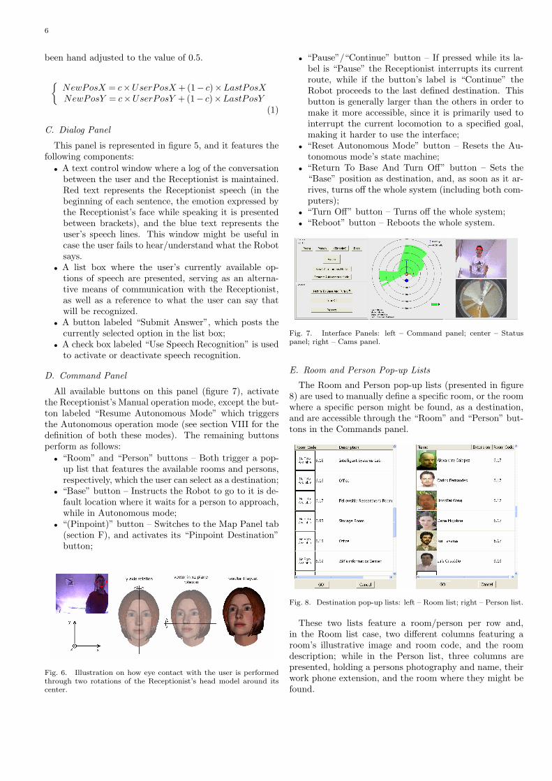
Fig. 7. Interface Panels: left – Command panel; center – Statuspanel; right – Cams panel.
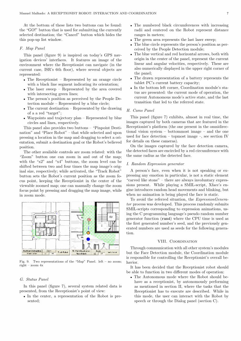
E. Room and Person Pop-up Lists
The Room and Person pop-up lists (presented in figure8) are used to manually define a specific room, or the roomwhere a specific person might be found, as a destination,and are accessible through the “Room” and “Person” but-tons in the Commands panel.
Fig. 8. Destination pop-up lists: left – Room list; right – Person list.
These two lists feature a room/person per row and,in the Room list case, two different columns featuring aroom’s illustrative image and room code, and the roomdescription; while in the Person list, three columns arepresented, holding a persons photography and name, theirwork phone extension, and the room where they might befound.
Manuel Malhado: A RECEPTIONIST ROBOT: INTERACTION AND COORDINATION 7
At the bottom of these lists two buttons can be found:the “GO!” button that is used for submitting the currentlyselected destination; the “Cancel” button which hides thethis pop-up list window.
F. Map Panel
This panel (figure 9) is inspired on today’s GPS nav-igation devices’ interfaces. It features an image of theenvironment where the Receptionist can navigate (in thecurrent case, ISR’s 6th floor), where several objects arerepresented:
• The Receptionist – Represented by an orange circlewith a black line segment indicating its orientation;
• The laser sweep – Represented by the area coveredwith intersecting green lines;
• The person’s position as perceived by the People De-tection module – Represented by a blue circle;
• The current destination – Represented by the drawingof a a red “target”;
• Waypoints and trajectory plan – Represented by bluecircles and lines, respectively.
This panel also provides two buttons – “Pinpoint Desti-nation” and “Place Robot” – that while selected and uponpressing a location in the map and dragging to select a ori-entation, submit a destination goal or the Robot’s believedposition.
The other available controls are zoom related: with the“Zoom” button one can zoom in and out of the map;with the “x2” and “x4” buttons, the zoom level can beshifted between two and four times the map image’s orig-inal size, respectively; while activated, the “Track Robot”button sets the Robot’s current position as the zoom fo-cus point, keeping the Receptionist in the center of theviewable zoomed map; one can manually change the zoomfocus point by pressing and dragging the map image, whilein zoom mode.
Fig. 9. Two representations of the “Map” Panel. left – no zoom;right – zoom 4x
G. Status Panel
In this panel (figure 7), several system related data ispresented, from the Receptionist’s point of view:
• In the center, a representation of the Robot is pre-sented;
• The numbered black circumferences with increasingradii and centered on the Robot represent distanceranges in meters;
• The green area represents the last laser sweep;• The blue circle represents the person’s position as per-
ceived by the People Detection module;• The blue vertical and red horizontal arrows, both with
origin in the center of the panel, represent the currentlinear and angular velocities, respectively. These arealso numerically displayed in the upper right corner ofthe panel;
• The drawn representation of a battery represents thetablet PC’s current battery capacity;
• In the bottom left corner, Coordination module’s sta-tus are presented: the current mode of operation, thecurrent Autonomous mode’s active state, and the lasttransition that led to the referred state.
H. Cams Panel
This panel (figure 7) exhibits, almost in real time, theimages captured by both cameras that are featured in theReceptionist’s platform (the one present in the omnidirec-tional vision system – bottommost image – and the oneused for face detection – topmost image –, see section IVfor details on these cameras).
On the images captured by the face detection camera,the detected faces are encircled by a red circumference withthe same radius as the detected face.
I. Random Expression generator
A person’s face, even when it is not speaking or ex-pressing any emotion in particular, is not a static element“carved like stone” – there are always involuntary expres-sions present. While playing a SMIL-script, Xface’s en-gine introduces random head movements and blinking, butwhen no animation is being played the face is static.
To avoid the referred situation, the ExpressionGenera-tor process was developed. This process randomly submitsSMIL-scripts corresponding to expression animations, us-ing the C programming language’s pseudo random numbergenerator function (rand) where the CPU time is used asthe first generated number’s seed, and the previously gen-erated numbers are used as seeds for the following genera-tion.
VIII. Coordination
Through communication with all other system’s modulesbut the Face Detection module, the Coordination moduleis responsible for controlling the Receptionist’s overall be-havior.
It has been decided that the Receptionist robot shouldbe able to function in two different modes of operation:
• The Autonomous mode where the Robot should be-have as a receptionist, by autonomously performingas mentioned in section II, where the tasks that theReceptionist has to execute are described. While inthis mode, the user can interact with the Robot byspeech or through the Dialog panel (section C).
8
• The Manual mode should be considered as a methodof demonstrating particular Robot features, providinga way for the Robot to perform direct instructions.In this mode, the Robot is static and waiting for anymanual commands submitted through the Commandor Map panels (described in sections D and F respec-tively).
A. Behavior Model
Considering the Receptionist’s requirements for the Au-tonomous mode of operation, a Finite State Machine(FSM) [9] was considered the best choice as the modelof behavior to be used for the Receptionist’s automationneeds.
UML StateWisard4 was the chosen toolkit to implementthis module’s FSM. This toolkit acts like a Visual C++add-in and provides a Unified Modeling Language (UML)statecharts [12] programming mechanism.
It integrates two modeling tools, accessible through theVisual C++ environment. The first is the State Tree (fig-ure 10 in the right), where each of the system’s states isrepresented with its associated child states, transitions andEntry and Exit actions branching down from it. The sec-ond tool is the State Chart, which presents a graphicalrepresentation of the system’s states, with child states con-tained inside their parent states, and the transitions con-necting these states.
Fig. 10. Representation example of the StateWizard’s State Chart(in the left) and State Tree (in the right) for a sample applications
The designed UML statechart model features three hi-erarchy levels with specific conceptual significance.
B. Modes of Operation Hierarchy Layer
The top level layer implements the Receptionists twopossible modes of operation, modeled by two states(AutonomousMode and ManualMode, and features a thirdstate (Booting) which is exited as soon as all system mod-ules’ YARP ports are connected, meaning that the Recep-tionist is ready to operate (figure 11).
Upon exiting the Booting state, the state machine tran-sits to the ManualMode state. In this state, all manualcommands emitted by the On-screen Interface and SpeechSyntheses module (section VII) are handled by a set ofinternal transitions.
4 http://www.intelliwizard.com/ (last retrieved in 09/2008)
Fig. 11. Modes hierarchy layer statechart
The behavior performed by the Receptionist robot whilein the AutonomousMode state is modeled by a lower levelsub state machine.
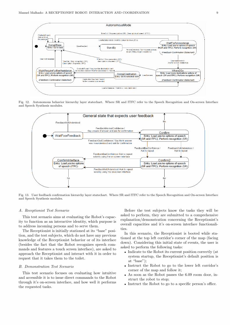
C. Autonomous Behavior Hierarchy Layer
At this hierarchy level, all individual behaviors thatmake up the receptionist overall behavior are modeled bystates, and transitions between these states are triggeredby external events that are fired upon arrival of specificdata through this module’s ports. In figure 12 this layer’sstatechart is presented.
D. User Feedback Confirmation Hierarchy Layer
In order to handle the uncertainty associated with theSpeech Recognition module’s recognized speech, requiredwhenever user feedback is requested by the Receptionist,the general purpose state machine represented in figure 13was developed. This state machine purpose is to ask theuser for a confirmation in case the recognizer is not sureof the speech that was comprehended, in which case theSpeech Recognition module returns a confidence value lessthan high.
Since the confirmation procedure is meant to be em-ployed in several Autonomous behavior statechart’s states,its design was developed so that it could be reused in eachof the these states as a sub state machine. Even thoughUML statechart models do not support multi parenthood,and so the same state machine cannot directly be enclosedin more than one higher level state, this model has beendeveloped in order for the same state structure, transitionevents, and action routines to be reused.
IX. overall system performance analysis
In order to evaluate how well the Receptionist performsboth tasks to which it was designed (to function as a re-ceptionist on the floor where it is stationed, and to serveas a demonstration platform of its robotic capacities), twodifferent test scenarios were considered, where three usersthat fit the profile of the Robot’s target audience (sectionI) are requested to interact with the platform and performa set of predefined tasks.
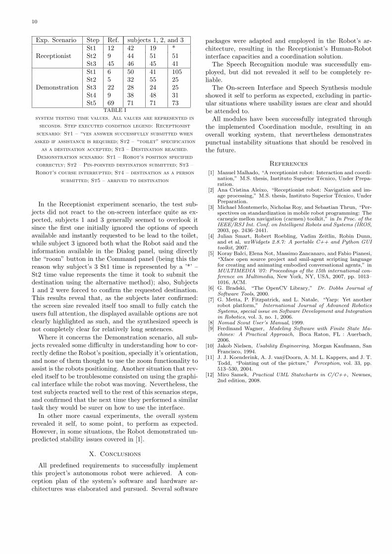
The time it takes for each test subject to perform eachrequired step to achieve the desired goals is also registered(Table I), and compared with the set of reference valuesobtained by an experienced user (that knows the platformand has optimized his interaction with it), while perform-ing the same task.
Manuel Malhado: A RECEPTIONIST ROBOT: INTERACTION AND COORDINATION 9
Fig. 12. Autonomous behavior hierarchy layer statechart. Where SR and ITFC refer to the Speech Recognition and On-screen Interfaceand Speech Synthesis modules.
Fig. 13. User feedback confirmation hierarchy layer statechart. Where SR and ITFC refer to the Speech Recognition and On-screen Interfaceand Speech Synthesis modules.
A. Receptionist Test Scenario
This test scenario aims at evaluating the Robot’s capac-ity to function as an interactive identity, which purpose isto address incoming persons and to serve them.
The Receptionist is initially stationed at its “base” posi-tion, and the test subjects, which do not have any previousknowledge of the Receptionist behavior or of its interface(besides the fact that the Robot recognizes speech com-mands and features a touch screen interface), are asked toapproach the Receptionist and interact with it in order torequest that it takes them to the toilet.
B. Demonstration Test Scenario
This test scenario focuses on evaluating how intuitiveand accessible it is to issue direct commands to the Robotthrough it’s on-screen interface, and how well it performsthe requested tasks.
Before the test subjects know the tasks they will beasked to perform, they are submitted to a comprehensiveexplanation/demonstration concerning the Receptionist’soverall capacities and it’s on-screen interface functionali-ties.
In this scenario, the Receptionist is booted while sta-tioned at the top left corridor’s corner of the map (facingdown). Considering this initial state of events, the user isasked to perform the following tasks:
• Indicate to the Robot its current position correctly (atsystem startup, the Receptionist’s default position isat “base”);
• Instruct the Robot to go to the lower left corridor’scorner of the map and follow it;
• As soon as the Robot passes the 6.09 room door, in-struct the robot to stop;
• Instruct the Robot to go to a specific person’s office.
10
Exp. Scenario Step Ref. subjects 1, 2, and 3
ReceptionistSt1 12 42 19 *St2 9 44 51 51St3 45 46 45 41
Demonstration
St1 6 50 41 105St2 5 32 55 25St3 22 28 24 25St4 9 38 48 31St5 69 71 71 73
TABLE I
system testing time values. All values are represented in
seconds. Step executed condition legend: Receptionist
scenario: St1 – “yes answer successfully submitted when
asked if assistance is required; St2 – “toilet” specification
as a destination accepted; St3 – Destination reached.
Demonstration scenario: St1 – Robot’s position specified
correctly; St2 – Pin-pointed destination submitted; St3 –
Robot’s course interrupted; St4 – destination as a person
submitted; St5 – arrived to destination
In the Receptionist experiment scenario, the test sub-jects did not react to the on-screen interface quite as ex-pected, subjects 1 and 3 generally seemed to overlook itsince the first one initially ignored the options of speechavailable and instantly requested to be lead to the toilet,while subject 3 ignored both what the Robot said and theinformation available in the Dialog panel, using directlythe “room” button in the Command panel (being this thereason why subject’s 3 St1 time is represented by a ’*’ –St2 time value represents the time it took to submit thedestination using the alternative method); also, Subjects1 and 2 were forced to confirm the requested destination.This results reveal that, as the subjects later confirmed:the screen size revealed itself too small to fully catch theusers full attention, the displayed available options are notclearly highlighted as such, and the synthesized speech isnot completely clear for relatively long sentences.
Where it concerns the Demonstration scenario, all sub-jects revealed some difficulty in understanding how to cor-rectly define the Robot’s position, specially it’s orientation,and none of them thought to use the zoom functionality toassist is the robots positioning. Another situation that rev-eled itself to be troublesome consisted on using the graphi-cal interface while the robot was moving. Nevertheless, thetest subjects reacted well to the rest of this scenarios steps,and confirmed that the next time they performed a similartask they would be surer on how to use the interface.
In other more casual experiments, the overall systemrevealed it self, to some point, to perform as expected.However, in some situations, the Robot demonstrated un-predicted stability issues covered in [1].
X. Conclusions
All predefined requirements to successfully implementthis project’s autonomous robot were achieved. A con-ception plan of the system’s software and hardware ar-chitectures was elaborated and pursued. Several software
packages were adapted and employed in the Robot’s ar-chitecture, resulting in the Receptionist’s Human-Robotinterface capacities and a coordination solution.
The Speech Recognition module was successfully em-ployed, but did not revealed it self to be completely re-liable.
The On-screen Interface and Speech Synthesis moduleshowed it self to perform as expected, excluding in partic-ular situations where usability issues are clear and shouldbe attended to.
All modules have been successfully integrated throughthe implemented Coordination module, resulting in anoverall working system, that nevertheless demonstratespunctual instability situations that should be resolved inthe future.
References
[1] Manuel Malhado, “A receptionist robot: Interaction and coordi-nation,” M.S. thesis, Instituto Superior Tecnico, Under Prepa-ration.
[2] Ana Cristina Aleixo, “Receptionist robot: Navigation and im-age processing,” M.S. thesis, Instituto Superior Tecnico, UnderPreparation.
[3] Michael Montemerlo, Nicholas Roy, and Sebastian Thrun, “Per-spectives on standardization in mobile robot programming: Thecarnegie mellon navigation (carmen) toolkit,” in In Proc. of theIEEE/RSJ Int. Conf. on Intelligent Robots and Systems (IROS,2003, pp. 2436–2441.
[4] Julian Smart, Robert Roebling, Vadim Zeitlin, Robin Dunn,and et al, wxWidgets 2.8.7: A portable C++ and Python GUItoolkit, 2007.
[5] Koray Balci, Elena Not, Massimo Zancanaro, and Fabio Pianesi,“Xface open source project and smil-agent scripting languagefor creating and animating embodied conversational agents,” inMULTIMEDIA ’07: Proceedings of the 15th international con-ference on Multimedia, New York, NY, USA, 2007, pp. 1013–1016, ACM.
[6] G. Bradski, “The OpenCV Library,” Dr. Dobbs Journal ofSoftware Tools, 2000.
[7] G. Metta, P. Fitzpatrick, and L. Natale, “Yarp: Yet anotherrobot platform,” International Journal of Advanced RoboticsSystems, special issue on Software Development and Integrationin Robotics, vol. 3, no. 1, 2006.
[8] Nomad Scout User’s Manual, 1999.[9] Ferdinand Wagner, Modeling Software with Finite State Ma-
chines: A Practical Approach, Boca Raton, FL : Auerbach,2006.
[10] Jakob Nielsen, Usability Engineering, Morgan Kaufmann, SanFrancisco, 1994.
[11] J. J. Koenderink, A. J. vanyDoorn, A. M. L. Kappers, and J. T.Todd, “Pointing out of the picture,” Perception, vol. 33, pp.513–530, 2004.
[12] Miro Samek, Practical UML Statecharts in C/C++, Newnes,2nd edition, 2008.