a quadratic motion-based object-oriented video codecportal.ku.edu.tr/~yyemez/imagecomm00.pdf ·...
TRANSCRIPT

Signal Processing: Image Communication 15 (2000) 729}766
A quadratic motion-based object-oriented video codecq
Y. Yemez, B. Sankur*, E. AnarmmDepartment of Electrical and Electronics Engineering, Bogy azic7 i University, 80815, Bebek, IQ stanbul, Turkey
Received 15 September 1997
Abstract
A novel motion-based object-oriented codec for video transmission at very low bit-rates is proposed. The objectmotion is modeled by quadratic transform with coe$cients estimated via a nonlinear quasi-Newton method. Thesegmentation problem is put forward as a constrained optimization problem which interacts with the motion estimationprocess in the course of region growing. A context-based shape coding method which takes into account the imagesynthesis error as well as the geometric distortion, is also proposed. Quantitative and subjective performance results ofthe codec on various test sequences illustrate the superior performance of the method. ( 2000 Elsevier Science B.V. Allrights reserved.
Keywords: Object-oriented video coding; Motion segmentation; Region growing; Quadratic transform; Shape polygonization
1. Introduction
The research activities for very low bit-rate video transmission, in the context of model-based coding, havebeen centered around the development of the new international standard, so-called MPEG-4 [24]. Thisstandard, besides high compression, also addresses content-based functionalities such as interactivity (e.g.,multimedia data access, manipulation) and scalability (e.g., user or automated selection of decoded quality ofobjects in the scene, database browsing at di!erent qualities). Therefore novel video coding schemes aredesired, which can address the content of the video by di!erentiating the objects or the regions of interest inthe scene. These schemes also exploit in general the properties of the human visual system, as well as theinherent temporal redundancy using more sophisticated motion estimation.
Conventional schemes such as block-based H.261/263 standard, are mostly independent of the scenecontent. As far as model-based algorithms are concerned, on one side stand the semantic-based schemeswhich are committed to speci"c content, such as those based on head-and-shoulder wireframe models. Onthe other side, the object-oriented schemes make no a priori assumptions about the scene content, and are
qThis work was supported by TUG BI0 TAK under contracts EEEAG-139 and EEEAG-83.*Corresponding author. Fax: 90-212-2872465.E-mail address: [email protected] (B. Sankur).
0923-5965/00/$ - see front matter ( 2000 Elsevier Science B.V. All rights reserved.PII: S 0 9 2 3 - 5 9 6 5 ( 9 9 ) 0 0 0 1 7 - X

Nomenclature
A motion parameter setC color parameter setD geometric shape distortionD
.!9geometric shape distortiontolerance towards inside
D@.!9
geometric shape distortiontolerance towards outside
E mean-square synthesis errorG overall coding costJ overall modeling errorL labeling mapp motion parameter vectorP image plane partitionP(v
k~1, v
k) polygon edge
R object region
R(vk) region lying between the shape
and the polygon edge P(vk~1
)R image planesl
boundary pixelsvk
boundary pixel associated to vk
S shape parameter settil
band pixel associated to ¹(sl)
¹ band¹(s
l) subset of ¹ associated to s
l¹CH
error threshold of change detection¹
MCerror threshold of segmentation
vk
vertex pixel< ordered set of verticesc shape bit-rate for a polygon edgeC shape bit-rate for a polygon
therefore applicable to a more general class of images. Object-oriented methods model the real world interms of objects which are speci"ed by three sets of parameters de"ning the motion, shape and color (texture)information. In this respect object-oriented codecs have gained prominence since they both allow forenhanced functionality and also they have the potential for improved rendition using advanced motionmodels.
The three important tasks in an object-oriented coding scheme are object modeling, image analysis andsynthesis, and parameter coding, as shown in the block diagram of Fig. 1. Image analysis purports to segmentthe scene into objects. The object modeling part refers to the de"nition of objects and determines thegoal-directed criteria of the segmentation process. Segmentation generally yields arbitrarily shaped andtextured regions corresponding to di!erently moving objects. Finally, parameter coding aims to coding of theshape, color and motion parameters of resulting objects, whose bit budget should be e$ciently shared amongthese three types of parameters.
The most crucial part of an object-oriented coder is the analysis part, in which the scene is segmented intoobjects under the chosen object model. The main approaches in the literature can be grouped under twocategories:
Temporal segmentation. The goal of temporal segmentation in an object-oriented coder is to subdivide thescene into regions each of which corresponds to an object with a di!erent motion characteristic. In [21], thesegmentation depends purely on motion information, and proceeds hierarchically from larger objects tosmaller ones. The scene is "rst divided into background and changed regions. The changed region is furtherprocessed and segmented into model compliance, model failure and uncovered regions [14]. Modelcompliance regions correspond to objects for which the motion can be modeled successfully by the chosenobject model, and thus can be compensated without further color coding. On the other hand, model failureand uncovered regions fail to satisfy the object model, and therefore are subject to color coding. The variousobject models utilized in such a scheme are 2D rigid objects with 3D motion [21], 2D #exible objects with 2Dmotion [12], 3D rigid objects with 3D motion [21], 3D #exible objects with 3D motion [23]. Although thisscheme, in terms of bit-rate-quality tradeo!, works well for head-shoulder scenes of videophone sequences,for which it has been designed for, it may fail for scenes of a di!erent content.
730 Y. Yemez et al. / Signal Processing: Image Communication 15 (2000) 729}766
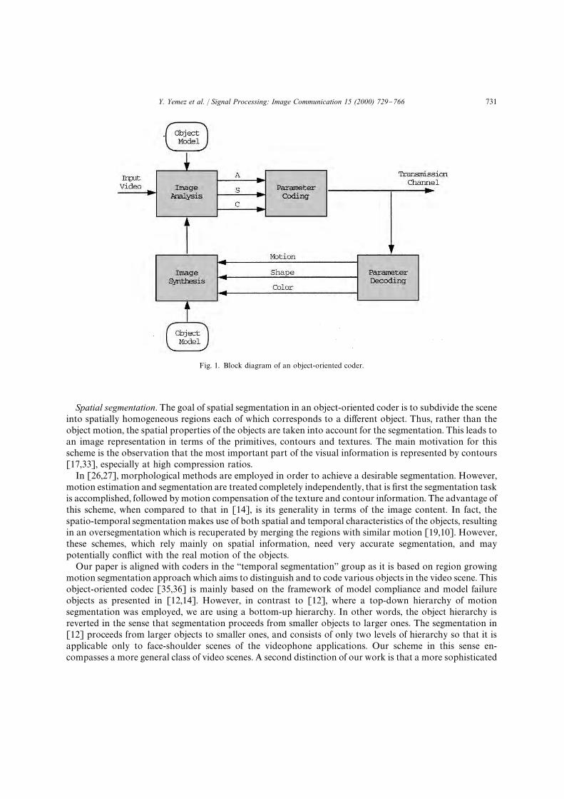
Fig. 1. Block diagram of an object-oriented coder.
Spatial segmentation. The goal of spatial segmentation in an object-oriented coder is to subdivide the sceneinto spatially homogeneous regions each of which corresponds to a di!erent object. Thus, rather than theobject motion, the spatial properties of the objects are taken into account for the segmentation. This leads toan image representation in terms of the primitives, contours and textures. The main motivation for thisscheme is the observation that the most important part of the visual information is represented by contours[17,33], especially at high compression ratios.
In [26,27], morphological methods are employed in order to achieve a desirable segmentation. However,motion estimation and segmentation are treated completely independently, that is "rst the segmentation taskis accomplished, followed by motion compensation of the texture and contour information. The advantage ofthis scheme, when compared to that in [14], is its generality in terms of the image content. In fact, thespatio-temporal segmentation makes use of both spatial and temporal characteristics of the objects, resultingin an oversegmentation which is recuperated by merging the regions with similar motion [19,10]. However,these schemes, which rely mainly on spatial information, need very accurate segmentation, and maypotentially con#ict with the real motion of the objects.
Our paper is aligned with coders in the `temporal segmentationa group as it is based on region growingmotion segmentation approach which aims to distinguish and to code various objects in the video scene. Thisobject-oriented codec [35,36] is mainly based on the framework of model compliance and model failureobjects as presented in [12,14]. However, in contrast to [12], where a top-down hierarchy of motionsegmentation was employed, we are using a bottom-up hierarchy. In other words, the object hierarchy isreverted in the sense that segmentation proceeds from smaller objects to larger ones. The segmentation in[12] proceeds from larger objects to smaller ones, and consists of only two levels of hierarchy so that it isapplicable only to face-shoulder scenes of the videophone applications. Our scheme in this sense en-compasses a more general class of video scenes. A second distinction of our work is that a more sophisticated
Y. Yemez et al. / Signal Processing: Image Communication 15 (2000) 729}766 731

Fig. 2. Block diagram of the proposed motion-segmentation based coder (bold line: image #ow; thin lines: parameter #ow). Thequadratic motion estimation block is further expanded in Fig. 6.
motion model is employed in the temporal segmentation. In fact, the motions of objects are modeled viaquadratic transform, which enables a more general and #exible modeling as compared to the other lowerorder polynomial models used in the literature such as the a$ne transform and the pure translation. Thequadratic model can represent 3-D motion of parabolic surfaces. A third contribution of the paper is theformulation of the segmentation problem in terms of the rate-distortion theory as an optimal descriptionproblem. The parametric representation resulting from the quadratic transform model avails us with thepossibility of employing a region growing approach for the iterative solution of the segmentation problem.Finally a novel shape coding algorithm is developed for e$cient polygonization of segment boundariessimultaneously taking into account both geometrical as well as image synthesis, and therefore motionrepresentation distortions. The block diagram of the proposed motion-segmentation based coder is shown inFig. 2.
The paper is organized as follows. In Section 2, the problem of quadratic object motion modeling isconsidered. In particular, the estimation procedure for the coe$cients of the quadratic transform asa nonlinear optimization problem is addressed. The quasi-Newton optimization method, which is used forestimation, is presented in conjunction with a multiresolution and multiframe scheme. Section 3 addressesthe analysis part of the algorithm, which aims to describe the scene in terms of moving objects with arbitrarilyshaped and textured regions. The segmentation problem is formulated by a constrained optimizationproblem. The problem of "nding the optimum description under the chosen object model is then solvedsuboptimally by an iterative region growing procedure. Section 4 addresses the coding issues of the shape,motion and color (texture) of the motion segments. A shape coding technique, which is based on polygonapproximation and takes into account not only the geometric shape distortion, but also the synthesis error interms of image intensity caused by the shape distortion, is proposed. In Section 5, the simulation results of theproposed approach are given and its performance on various test sequences is illustrated, both subjectivelyand quantitatively. Finally, Section 6 gives the concluding remarks.
2. Quadratic motion estimation
2.1. Object motion modeling
In most video coding schemes, the motion is modeled by a linear combination of 2D polynomial basisfunctions [5]. Translational and a$ne models, which correspond to the zeroth- and "rst-order polynomialtransforms, are the most commonly used models in conventional and object-oriented coders. The use of
732 Y. Yemez et al. / Signal Processing: Image Communication 15 (2000) 729}766

higher degree polynomial tranforms such as the quadratic transform [4,16], however, may lead to superiorcoding e$ciencies since they are capable of modeling a broader class of object motions and of course,inherently contain the lower order representations.
The quadratic transform used for object motion modeling, relates the coordinates of an object pixelbetween two consecutive image frames at time instances t!1 and t. (This generic time di!erence denotes inthis work the interval between two frames k apart, k"1, 2,2.) Thus, the image intensity I(x, y, t) for anobject region is mapped from I(u(x, y), v(x,y), t!1), where the new coordinates are given by
u(x, y)"a1x2#a
2y2#a
3xy#a
4x#a
5y#a
6,
v(x,y)"b1x2#b
2y2#b
3xy#b
4x#b
5y#b
6.
(1)
The use of a quadratic transform for motion modeling is meaningful only under certain physical conditionsof the 3D geometric surface, of the 3D real motion of the objects, and of the projection of objects onto the 2Dimage plane. The quadratic transform gives an exact description of the 3D rotation, translation and scaling ofan object with a parabolic surface under parallel projection [4]. Thus, the true object motion is modeled by
U"RX#d, (2)
where U"(;,<,=)T and X"(X,>, Z)T stand for object space coordinates, R is the rotation matrix, and d isthe translation vector. Such a model inherently allows any linear deformation, but fails to model nonlineardeformations. On the other hand, the parabolic facet for surface modeling can be written as
Z"c1X2#c
2X>#c
3>2#c
4X#c
5>#c
6. (3)
The parabolic facet assumption (3) and the true object motion model (2) yield the quadratic transformationin terms of image plane coordinates under parallel projection. The quadratic transform is also a goodapproximation for the rigid motion and the linear deformation of an object with a quadratic surface undercentral projection [4] (see Fig. 3).
The quadratic transform models the real 3D world in terms of quadratic (parabolic) surfaces movingrigidly, or deforming linearly. Theoretically, the higher the degree of the polynomial representation, the moregeneral is the model. One may then inquire whether even higher degree models would not be advantageous.In general, higher degree models will not necessarily result in a more e$cient coding. First, higherpolynomial representations need more parameters, hence increase the bit-rate. Second, with higher orderpolynomials the dimensionality and the nonlinearity of the optimization process employed for the parameter
Fig. 3. Physical interpretation of the quadratic transform.
Y. Yemez et al. / Signal Processing: Image Communication 15 (2000) 729}766 733

estimation increase. Our experiments have in fact shown that using third-order representations, for example,may yield even less accurate results compared to those of the quadratic transform. Thus, we believe that thequadratic transform in (1) represents the best compromise between modeling sophistication and coding gain.
2.2. Motion estimation
The motion estimation, in the case of continuous parameter space, is carried out via an optimizationprocess that utilizes spatio-temporal properties of the image intensity, and is based on di!erential methods.The error function in motion estimation problem is given by the mean-squared error
E(p, R)" +x|R
DFD2(x, p), (4)
where R is the support region of the object. The parameter vector p is determined by the quadratic transformcoe$cients in (1), p"(a
1,2, a
6, b
1,2, b
6)T, DFD denotes the displaced frame di!erence given by
DFD(x,p)"I(x, t)!I(u, t!1), where u is given by the quadratic transform of x. In the sequel, the motionparameter set will be indicated by the symbol A"a
k, b
k, k"1,2, 6. For example, A
iwill be used to denote
the set of 12 motion parameters of the region Ri. In other words, the motion parameters will be denoted by
p and A, respectively in the context of vector operations and set operations.The error function in (4) is a nonlinear function, and the minimization of this function is possible only via
nonlinear iterative di!erential methods such as the quasi-Newton method [25,7], as used in our implementa-tion.
Di!erential algorithms start with an initial value, which is then iterated towards the optimum byaccumulating the information. Newton's method is based on a quadratic model. To illustrate the case let usconsider any arbitrary N-dimensional nonlinear function f ( ) ) of p. Using the truncated Taylor seriesexpansion of f (p) about the point p
k, the quadratic model function q
k(d) can be written, at iteration k, as
f (pk#d)+q
k(d)"f (p
k)#uT
kd#1
2dTH
kd, (5)
where d"p!pk. In (5), u
kdenotes the gradient of the function, and H
kis the Hessian matrix.
One disadvantage of Newton's method is the need for the second-order derivatives of the function, and theother is that the Hessian matrix H must be positive de"nite to assure convergence. The latter disadvantagecan be avoided by Newton's method with line search for "nding successive directions along which lineminimizations are performed so that the current point p
kconverges towards the minimum. The so-called
`quasi-Newtona method, which is also based on line minimizations, avoids the computation of the Hessianmatrix at each iteration by updating the inverse Hessian matrix H~1
kin terms of the value of the function and
its "rst-order derivatives. The kth iteration of the quasi-Newton algorithm can be summarized by thefollowing three steps:1. set s
k"!H~1
kuk,
2. line minimization along skso that p
k`1"p
k#a
ksk,
3. update H~1k
into H~1k`1
,where s
kcorresponds to the direction along which the line minimization is carried out at iteration k, and a
kis
a constant determined by line minimization. The BFGS (Broyden, Fletcher, Goldfarb, Shanno) method forthe update of the Hessian matrix in [7], has been used in steps of the algorithm.
The "rst-order derivative of the error function E(p,R) in (4) can be computed numerically by
RE(p,R)
Rp "! +xn|R
2(I(xn, t)!I(u
n, t!1))
RI(un, t!1)
RuRuRp, (6)
734 Y. Yemez et al. / Signal Processing: Image Communication 15 (2000) 729}766

where un"(u
n, v
n) is given by (1) and
RuRp"C
x2
0
y2
0
xy
0
x
0
y
0
1
0
0
x2
0
y2
0
xy
0
x
0
y
0
1D, (7)
RI(x, t)
Rx "CRIRx
RIRyD. (8)
The partial derivatives with respect to x and y can be approximated by
RI(x,y, t)
Rx +1
2(I(x#1, y, t)!I(x!1, y, t)), (9)
RI(x,y, t)
Ry +1
2(I(x,y#1, t)!I(x,y!1, t)). (10)
A problem in computing the value of E(R, p) and its derivatives is that the mapped coordinates u, vcorrespond to real-valued transforms in continuous space whereas I(u, v) is de"ned only on a discrete grid.The image can be estimated on the grid coordinates by the bilinear interpolation [22]
I(u, v)"(1!a)((1!b)I([u], [v])#bI([u]#1, [v]))#a((1!b)I([u], [v]#1)#bI([u]#1, [v]#1)),
(11)
where ([u], [v]) are the integral parts and (a,b) are the fractional parts of the coordinate (u, v). The gradientvector in (6) must similarly be estimated on the coordinates (u, v) via interpolation on the original grid. Hence,Eq. (6) can alternatively be calculated by
RE(p, R)
Rp " +xn|R
2(I(xn, t)!I(u
n, t!1))
RI(xn, t)
RxRxRuRuRp, (12)
where
ARxRuB
~1"C2a
1x#a
3y#a
42a
2y#a
3x#a
52b
1x#b
3y#b
42b
2y#b
3x#b
5D. (13)
2.3. Multiscale estimation
The quasi-Newton methods are assured to converge globally in N iterations if the function f (p) to beminimized is quadratic, regardless of the starting point p
0. This is generally not the case for the error function
in (4) which is set up for arbitrarily textured images. In other words, the error expression in (4) would bea quadratic function only when the related region corresponds to a quadratic surface. However, real-worldimages, especially textured areas do not form exactly quadratic surfaces. Thus, there may exist many spuriousminima on the trajectory between the starting point to the global minimum. In order to prevent thequasi-Newton algorithm from getting stuck in a local minimum, we recourse to the following measures:(a) proper initialization of p, (b) multiresolution scheme, and (c) tracking of motion in skipped frames. Let us
Y. Yemez et al. / Signal Processing: Image Communication 15 (2000) 729}766 735

emphasize once more that with the multiresolutional scheme the lower bands are less textured, and theirregions can be more easily modeled as quadratic surfaces. This is the reason why better initial estimates canbe obtained. In summary, the interplay of spatial and temporal multiresolution guarantees and speeds up theconvergence of the quasi-Newtonian methods.
The proper initialization of p, recalling (1), is based on the following observation:
u(0, 0)"a6, v(0, 0)"b
6. (14)
Thus the coe$cients of the zeroth-order terms corresponding to the translational part are determined by thedisplacement of the point (0, 0), i.e., the geometric center of the support region. The vertical and horizontaldisplacements of the centroid of a region R, which can be estimated by a classical block matching technique,correspond to the initial values of a
6and b
6, respectively.
A second measure to improve convergence is a multiresolution scheme as in [15,5,16], which spatiallysmooths the consecutive images and reduces the number of the minima arising from the high-frequencycomponents. The estimates obtained from the smoothed images can then be used for a more accurateestimate in the higher bandwidth images.
Thirdly, the motion information in the skipped frames, which is usually neglected in coding schemes, canalso be incorporated so that the motion parameters evolve temporally through the skipped frames andconverge towards the global minimum. This is needed especially when there exists severe motion asa consequence of frame skipping.
Consider the problem of motion estimation between two P-frames (predictive coded frames), Inand I
n~q,so that there are q!1 S-frames (skipped frames) in between (Fig. 4). Notice that in this algorithmthe motion estimation proceeds in the backward sense. The skipped frames are only used by theencoder in order to improve the performance of the estimation, but they are not coded and transmittedto the receiver. The motion of each object in the scene between the P-frames is determined by aquadratic transform coe$cient vector which can be denoted by p(q). Suppose that the motion of an objectbetween the P-frame I
nand a skipped frame I
n~k, k(q has been estimated. This already estimated parameter
vector p(k) can then be used as an initial estimate for the quasi-Newton algorithm to predict the motionbetween the frames I
nand I
n~k~1, represented by the coe$cient vector p(k#1). Thus the evolution of the
shapes of the objects throughout the time interval (n, n!q) are inherently modeled by a tubular surfacewhere the shape of the object at each discrete time instant corresponds to a cross-section of the surface, asillustrated in Fig. 4.
Fig. 4. Incorporation of the motion information in the skipped (S) frames. Notice that the motion estimation proceeds backwards.
736 Y. Yemez et al. / Signal Processing: Image Communication 15 (2000) 729}766
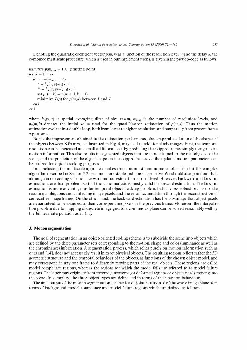
Denoting the quadratic coe$cient vector p(m, k) as a function of the resolution level m and the delay k, thecombined multiscale procedure, which is used in our implementations, is given in the pseudo-code as follows:
initialize p(m.!9
#1, 0) (starting point)for k"1 : q do
for m"m.!9
: 1 doI"h
m(x, y)*In
(x, y)I@"h
m(x, y)*I
n~k(x, y)
set p0(m, k)"p(m#1, k!1)
minimize E(p) for p(m, k) between I and I@end
end
where hm(x, y) is spatial averaging "lter of size m]m, m
.!9is the number of resolution levels, and
p0(m, k) denotes the initial value used for the quasi-Newton estimation of p(m, k). Thus the motion
estimation evolves in a double loop, both from lower to higher resolution, and temporally from present frameq past one.
Beside the improvement obtained in the estimation performance, the temporal evolution of the shapes ofthe objects between S-frames, as illustrated in Fig. 4, may lead to additional advantages. First, the temporalresolution can be increased at a small additional cost by predicting the skipped frames simply using q extramotion information. This also results in segmented objects that are more attuned to the real objects of thescene, and the prediction of the object shapes in the skipped frames via the updated motion parameters canbe utilized for object tracking purposes.
In conclusion, the multiscale approach makes the motion estimation more robust in that the complexalgorithm described in Section 2.2 becomes more stable and noise insensitive. We should also point out that,although in our coding scheme, backward motion estimation is considered. However, backward and forwardestimations are dual problems so that the same analysis is mostly valid for forward estimation. The forwardestimation is more advantageous for temporal object tracking problem, but it is less robust because of theresulting ambiguous and con#icting image pixels, and the error accumulation through the reconstruction ofconsecutive image frames. On the other hand, the backward estimation has the advantage that object pixelsare guaranteed to be assigned to their corresponding pixels in the previous frame. Moreover, the interpola-tion problem due to mapping of discrete image grid to a continuous plane can be solved reasonably well bythe bilinear interpolation as in (11).
3. Motion segmentation
The goal of segmentation in an object-oriented coding scheme is to subdivide the scene into objects whichare de"ned by the three parameter sets corresponding to the motion, shape and color (luminance as well asthe chrominance) information. A segmentation process, which relies purely on motion information such asours and [14], does not necessarily result in exact physical objects. The resulting regions re#ect rather the 3Dgeometric structure and the temporal behaviour of the objects, as functions of the chosen object model, andmay correspond in any one frame to di!erently moving parts of the real objects. These regions are calledmodel compliance regions, whereas the regions for which the model fails are referred to as model failureregions. The latter may originate from covered, uncovered, or deformed regions or objects newly moving intothe scene. In summary, the three object types are delineated in terms of their motion behaviour.
The "nal output of the motion segmentation scheme is a disjoint partition P of the whole image plane R interms of background, model compliance and model failure regions which are de"ned as follows:
Y. Yemez et al. / Signal Processing: Image Communication 15 (2000) 729}766 737

A region Riis said to be a background region, and denoted by RBG
i, if and only if the frame di!erence
FD(Ri))¹BG, where
FD(Ri)" 1
Ni
+x|Ri
(In(x)!I
n~1(x))2,
and ¹BG
is a prede"ned error threshold. The whole background region RBG"6NBG
i/1RBG
i, where N
BGis the
number of background regions, consists of those patches where the temporal changes are not signi"cant andcorrespond to either stationary background or the objects with negligible motion. A region R
iLR!RBG is
said to be a model compliance region, denoted by RMCi
, if and only if minAE(R
i,A))¹
MC, where ¹
MCis the
error threshold determining whether the motion model fails or not. A region RiLR is said to be a model
failure region, denoted by RMFi
, if and only if minAE(R
i, A)'¹
MC, and consequently, no parameter set A
ican
be associated with such a model failure region. In conclusion, the whole partition is given by
R"RBGXRMCXRMF, (15)
where RMC"6NMC
i/1RMC
iand RMF"6N
MFi/1
RMFi
. The total number of MC and MF regions are denoted byN
MCand N
MF, respectively.
In an object-oriented coding scheme a region with its motion, shape and color properties is called anobject. Model compliance and model failure objects are de"ned below: A model compliance object OMC
i,
associated with a model compliance region RMCi
, is de"ned by two parameter sets, SMCi
for the boundary shapeof the support region and AMC
ifor the motion information. A model failure object OMF
i, associated with
a model failure region RMFi
, is de"ned by two parameter sets, SMFi
for the boundary shape of the supportregion and CMF
ifor the color information. Thus, the motion and the shape of MC objects, and the shape and
the color of MF objects are coded and transmitted.Finally, the segmentation information is described by a labeling de"ned as follows: The labeling map
L : R2PR associates each region Riwith a label such that
L(x,y)"G0 if (x, y)3RBG,
!i if (x, y)3RMFi
,
i if (x, y)3RMCi
.
3.1. Segmentation as an optimization
An object-oriented coder should optimize the tradeo! between cost and quality of coding. Thus both themodeling error in MC regions, the coding cost of the partition information and the size of resulting MFregions should be kept as small as possible. The overall segmentation-estimation problem can be formulatedby the following constrained optimization problem:
minP
J#jG subject to ∀i, E(RMCi
,AMCi
))E.!9
, (16)
where
J(RMC,AMC)"N
MC
+i/1
E(RMCi
,AMCi
) (17)
738 Y. Yemez et al. / Signal Processing: Image Communication 15 (2000) 729}766

and
G"G(SMC,SMF,AMC,CMF). (18)
This optimization problem then becomes the problem of "nding a partition P of R such that the functionJ#jG is minimized under the given constraint, where j is a weighting constant. Here, J denotes themodeling error which is given by the model compliance regions and the associated motion parameters. In(17), AMC"6N
MCi/1
AMCi
denotes the concatenation of the object motion vectors.The coding cost, or equivalently the bit-rate G in (18) depends on the total shape parameter set S of the
MF and MC regions, the whole motion parameter set of the MC regions and the color of the MF regions.Recalling that the cost of color coding is relatively high, the size of the MF regions and the number of theresulting MC regions should be kept as small as the resulting modeling error in (17) allows. Moreover,smooth boundary contours are desired, since the shape coding cost (18) also increases with the complexityand details of the contours. Finally, note that (17) assumes errorless parameter coding, i.e., the error resultingfrom parameter coding is not included in the objective function.
The solution of this sizeable nonlinear optimization problem, which can also be considered as an optimumdescription problem, is only possible via iterative procedures in which the segmentation and estimationprocesses are employed in interaction. Although such iterative approaches to this optimization problem canonly yield suboptimal solutions, in practice, one obtains adequate performance.
3.2. A novel motion segmentation
The segmentation methods in object-oriented schemes, using motion information, are usually hierarchi-cally structured [14,4], that is proceeding from larger objects to smaller ones. The hierarchy proceeds fromthe gross temporally changed and unchanged regions of the scene, to increasingly "ner di!erentiation ofchanged regions using motion compliance. This hierarchical procedure is iterated until all the objects aredi!erentiated so as to satisfy the object model, including all di!erently moving parts of the physical objects,the objects under occlusion or the objects occluding larger moving objects. This hierarchical procedure canbe visualized in Fig. 5.
In the spatio-temporal segmentation schemes such as [19], the scene is "rst oversegmented into spatiallyhomogeneous atomic regions. These atomic regions are then successively merged using the motion informa-tion, though the concepts of model compliance and model failure are not used. The segmentation scheme,thus, can be regarded as proceeding from smaller objects to larger ones.
The segmentation scheme proposed in this paper, is based on pure motion information keeping theframework of model compliance and model failure regions of [14]. However, the object hierarchy is revertedso as to proceed from smaller objects to larger ones, thus allowing a more #exible segmentation which iscloser to the optimum partition and which is applicable to a more general class of image sequences. Thebottom-up scheme is superior to the top-down approach in that (a) object detail can be controlled at anyresolution level, (b) the chance of missing small but semantically relevant objects, such as eyes and mouth invideophony is minimized, and (c) the scheme is independent of the scene content. On the contrary, thetop-down scheme can miss semantically important details and it is too much oriented towards head-and-shoulder scenes. The proposed scheme is based on region growing and region merges with re-estimation ofthe motion parameters after a joint operation.
In brief, the proposed segmentation technique, which employs a pixelwise region growing process, reliespurely on motion information so that no initial spatial segmentation is needed. The segmentation scheme asillustrated in Fig. 6 consists of six subtasks, two initial blocks for change detection and splitting into seedblocks, three blocks in the loop for motion estimation, merging and region growing, respectively, and one"nal block for eliminating spurious details. In the sequel these subtasks are detailed:
Y. Yemez et al. / Signal Processing: Image Communication 15 (2000) 729}766 739

Fig. 5. Illustration of the object hierarchy in an object-oriented coding scheme.
3.2.1. Change detection mapThe change detection subtask aims to di!erentiate the temporally changed and unchanged regions of the
scene. Unchanged regions denoted by RBG correspond to either stationary background or the objects withno apperant motion. In the change detection algorithm the image is "rst thresholded using the absolutedi!erence of the low-pass "ltered (3]3) versions II
n(x, y) and II
n~1(x, y) of consecutive images. Thus any FD
below a threshold ¹CH
is labeled as background (L(xk, y
k)"0), any above is initially declared as model failure
(L(xk, y
k)"!1). The label map is further subjected to (3]3) median "ltering in order to smooth the
boundaries between the changed and unchanged regions, and to remove some of the isolated pixels. In thebinary map (0,!1) any small region whose size is smaller than a prede"ned threshold, which was notremoved by median "ltering, is assigned to its surrounding region label.
3.2.2. Seed blocksThe region growing process starts from seed blocks that have motion model error E(RMC
i, AMC
i))¹
MC.
Thus the changed regions (regions with label `!1a) are split into non-overlapping blocks Biof constant size
(e.g. 7]7), each subjected to a motion estimation process in terms of the quadratic model parameters. Ifa block B
ipartly consists of unchanged pixels, then the estimation is carried out only for the part
corresponding to the changed pixels. Those blocks for which the model error is below the prede"nedthreshold ¹
MCare labeled as the seed blocks of the objects in the scene. The seed blocks are assumed to fall
inside the object regions and prone to further growth. The blocks for which the model error is above the
740 Y. Yemez et al. / Signal Processing: Image Communication 15 (2000) 729}766

Fig. 6. Flowchart of the motion-based region growing segmentation.
threshold ¹MC
are assumed to fall either onto the boundaries of di!erently moving objects or into the modelfailure regions. These boundary blocks are not assigned any label and are handled in the following steps.
The size of the blocks in the initial partition should be chosen large enough such that the number of pixelsin the blocks su$ces for an accurate estimation of the 12 quadratic transform coe$cients, but small enoughto delineate the objects of interest in the scene. So the algorithm is as follows:
for each block Bido
EH"minAi
E(Bi, A
i)
if EH)¹MC
then L(x, y)"i ∀(x, y)3Bi
end
The output of this algorithm, as illustrated in the second silhouette in Fig. 6, is a rough segmentation of thescene into MC regions, MF regions and background, which needs to be further re"ned.
3.2.3. Region growingTo re"ne the rough partition resulting from `seed blocksa stage, a merging and pixelwise growing process
of the model compliance regions into both the neighboring model failure and model compliance regions, isexecuted.
Y. Yemez et al. / Signal Processing: Image Communication 15 (2000) 729}766 741

Region growing of MC regions into MF regions. Since the color information of MF objects is expensive tocode, these regions should be minimized in both size and number. The initial roughly segmented MF regionsmay partly contain MC pixels, either because a block B
imay sit astride an MF and a neighboring MC
region, or astride two neighboring MC regions, each having di!erent motion vectors, for which a uniquemotion cannot be determined. To this e!ect in order to reduce the MF pixels, neighboring MC regions aregrown into MF regions to identify MF pixels that would rightly belong to a MC region according to theassociated motion. The resulting algorithm is as follows:
for each MF pixel (x, y) neighboring to RMCi
doif E((x, y),AMC
i))¹
MCthen L(x, y)"i
end
The above process is iterated until there remains no MF pixel (x, y) such that E((x, y),AMCi
))¹MC
, for anyneighboring RMC
i.
Region growing of a MC region into another MC region. Neighboring MC regions are also grown into eachother for those pixels of region i that would be better represented by the motion model of region j. The pixelsat the boundary of a region RMC
iare tested for the motion parameters AMC
jassociated with the neighboring
region RMCj
, and provided that the resulting error is less than that of AMCi
, the pixel is assigned to theneighboring region. Then the following procedure is iterated:
for each pixel (x, y)3RMCi
neighboring to RMCj
doif E((x, y),AMC
j)(E((x, y),AMC
i) then L(x, y)"j
end
Region growing of a MF region into a MC region. The MC regions of the initial segmentation may alsoinvolve MF pixels. Thus a region growing process should be employed so that MF regions grow into MCregions by checking the modeling error. The iteration of the following procedure aims to exploit these MFpixels:
for each MC pixel (x, y)3RMCi
neighboring to RMFj
doif E((x, y),AMC
i)'¹
MCthen L(x, y)"!j
end
Rexnement of the background regions. The threshold ¹CH
of the change detection algorithm is set to besmaller than the background discrimination threshold ¹
BGto prevent spurious background regions resulting
within homogeneous gray level patches in the MC regions. Therefore, the boundary between the MC regionsand the background should also be re"ned by the following algorithm:
for each MC pixel (x, y)3RMCi
neighboring to RBG doif DI
n(x, y)!I
n~1(x, y)D)E((x, y),AMC
i) then L(x, y)"0
end
and
for each BG pixel (x, y)3RBG neighboring to RMCi
doif DI
n(x, y)!I
n~1(x, y)D'E((x, y),AMC
i) then L(x, y)"i
end
742 Y. Yemez et al. / Signal Processing: Image Communication 15 (2000) 729}766

In addition, during the region growing process, each MC region RMCi
for which the frame di!erencebecomes less than the background discrimination threshold, that is FD(RMC
i))¹BG, should wholly be
assigned to the background.
3.2.4. Rexnement loopAs seen in Fig. 6, the initial segmentation scheme is re"ned in a loop of merging, region growing, and
motion estimation blocks to attain an optimal partition, and hence the bit-rate versus quality tradeo!s. There"nement loop has the following characteristics:
1. Region growing process is based on the assumption that the motion parameter set estimated for a MCregion is also valid for the outside pixels near its boundary. Thus the motion estimation procedure inherentlyestimates an object surface f (X,>,Z)"0, for which the motion parameter set is denoted by A
f. All yet
unlabeled boundary pixels are also considered part of this surface so long f (Xk,>
k,Z
k)+0 is approximately
satis"ed, hence the same Af
is also valid for (Xk,>
k, Z
k). Usually, as the regions grow away from their initial
support region their surface structure also changes such that this approximation will eventually lose itsvalidity. When a MC region cannot be further grown by the current parameter set A
f, i.e., by the current
surface representation f (X,>,Z)"0, a new set of motion parameters, denoted by Ag, are estimated so that
the resulting model is a better re#ection of the grown object surface g(X,>, Z)"0. Therefore, at each cycle ofthe region growing loop, a re-estimation of the motion model parameters of the MC regions which havegrown (or have become smaller) considerably (e.g., 10%) at the previous cycle is carried out.
2. The MC regions, which have newly been neighbors by having swallowed the intervening regions in thegrowth process, can potentially be merged at the successive cycles of the loop.
3. In the re"nement loop the error threshold ¹MC
can gradually be increased as one cycles through theloop. With this gradual increase, the ambiguous MF pixels that are simultaneously contended by twodi!erent MC regions can be correctly attributed to the MC region yielding a lower compensation error.Gradual increase of ¹
MCcan also be utilized for adjusting the cost-quality tradeo!, that is the error threshold
is increased gradually until the total size of MF regions becomes su$ciently small.
3.2.5. Motion re-estimationIn order to avoid the computational load of the quasi-Newton minimization at each cycle, a strategy which
is similar to the one used in [16] is adopted. The method presented in [16] is utilized for region mergingprocess, whereas the method described below aims to re-estimate the motion parameters of each modelcompliance region by making use of its already estimated parameters in previous iterations.
Let RI MCi
denote the updated version RMCi
so that (RI MCi
!RMCi
) X (RMCi
!RI MCi
) corresponds to the pixelswhich are removed or added by the motion "eld extension. The problem is to minimize the mean square errorfunction given by
+(xk,yk)|RI MC
i
(In(x
k, y
k)!I
n~1(u8
k, v8
k))2 (19)
and to obtain a new parameter vector p8 "[a8 , bI ] by using the already estimated p. The trick leading to a fastsolution is that u
kand v
kare already su$ciently good estimates, which are given by
uk"aTq
k, v
k"bTq
k(20)
for all (xk, y
k)3RI MC
i, where q
k"[x2
k, y2
k, x
kyk,x
k, y
k, 1].
Y. Yemez et al. / Signal Processing: Image Communication 15 (2000) 729}766 743

The Taylor series expansion of In~1
(u8k, v8
k) around (u
k, v
k) gives
In~1
(u8k, v8
k)"I
n~1(u
k, v
k)#RIn~1
(uk, v
k)
Rx (u8k!u
k)#RIn~1
(uk, v
k)
Ry (v8k!v
k), (21)
where the second and higher order terms can be neglected since the initial estimates ukand v
kare su$ciently
good. The above linear approximation, together with (19) yields the following equation for each (xk,y
k)3RI MC
i:
RIn~1
(uk, v
k)
Rx u8k#RIn~1
(uk, v
k)
Ry v8k"I
n(x
k, y
k)!I
n~1(u
k, v
k)#RIn~1
(uk, v
k)
Rx uk#RIn~1
(uk, v
k)
Ry vk. (22)
Overall, this results in an overdetermined system of linear equations:
Qp"z, (23)
where the kth rows of Q and z are given by
CRI
n~1(u
k, v
k)
RxRI
n~1(u
k, v
k)
Ry D?[1 xk
yk
xkyk
x2k
y2k] (24)
and
z(k)"In(x
k, y
k)!I
n~1(u
k, v
k)#RIn~1
(uk, v
k)
Rx uk#RIn~1
(uk, v
k)
Ry vk. (25)
Solution of (23) in terms of a and b, thus the new parameter set AI associated to RI MCi
can be obtained by thewell-known least-squares method.
3.2.6. MergingAs far as the #exibility of the object model allows, the number of the MC regions should be kept small to
curb the coding cost of motion and shape parameters. Successive merging of neighboring MC regions forwhich the motions can be represented by a single set of motion parameters can be achieved as follows:
for each neighboring RMCi
and RMCj
doEH"min
AE(RMC
iXRMC
j, A)
if EH)¹MC
then doL(x,y)"i, ∀(x, y)3RMC
jAMC
i"AH
endend
The above merging algorithm should be iterated so that the model compliance regions grow gradually bymerging until no neighboring MC regions with similar motion are left. The motion re-estimation for AH isagain carried out as in the previous step. The minimization strategy for merging is based on the fact that themotion of the regions to be merged is already known from the previous steps of the segmentation algorithm.Consider two neighboring MC regions RMC
iand RMC
j, and the associated quadratic transform coe$cient
vectors pi"[a
i, b
i], p
j"[a
j, b
j]. The problem is the determination pH such that
+(xk,yk)|RMC
iXR
MCj
(In(x
k, y
k)!I
n~1(uH
k, vH
k))2 (26)
744 Y. Yemez et al. / Signal Processing: Image Communication 15 (2000) 729}766

by using the already known ukand v
k. When expanded by Taylor series around the already known (u
k, v
k) for
each (xk, y
k)3RMC
iXRMC
j, which are su$ciently good estimates, the dependence of I
n~1(uH
k, vH
k) on u8
k!u
kand
v8k!v
kbecomes linear and the solution can be obtained by the least squares solution. This scheme for region
merging turns out to be better than, for example, motion "eld extension [28] whereby the motion parametersfor the whole merged region are equated to the motion parameters of the larger of the two regions. Anotheralternative is to write a linear system of equations which is given by
uHk"u
k, vH
k"v
k(27)
for all (xk, y
k)3RMC
iXRMC
jand to solve for pH. One can make recourse to these latter schemes, as in our
implementation, only when the merging method which is based on the Taylor series expansion as expoundedin (23), fails.
3.2.7. Post-processing of the segmentationA growth constraint is imposed to region growing of the re"nement loop, that demands that every
acquired pixel must have at least three other neighbors of the same label. However, despite this growthconstraint, the region boundaries can still be too active, and some post-processing of region contours isneeded to eliminate the spurious details of the segmentation output, corresponding to small regions orregions with noisy boundaries, which unnecessarily increase the coding cost. Region boundaries aresmoothed as follows:
f Majority xltering. In a 3]3 mask, the label of a pixel is changed to the label most frequently occurring.f Morphological closing with a disk structuring element of a small radius [11], e.g. r"1, smooths the
boundaries, fuses narrow breaks and long thin gulfs, eliminates small holes, and "lls gaps on theboundaries. Closing operation is applied successively to each region in the segmentation map. The order ofthe operation is important for the accuracy of the segmentation, since the closing operation has the e!ectof enlarging the regions: First, the MF regions should be closed, then the MC regions and "nally thebackground regions.
f Eliminating the small regions. The regions, either MF, MC or background, which are smaller thana prede"ned threshold size, are eliminated by merging. The MF and background regions smaller than thethreshold are merged into the neighboring larger regions with the most similar motion. The small MCregions are treated di!erently since they may still involve parts belonging to di!erent larger MC regions.Thus, these are set to be unlabeled and consequently a region growing loop is restarted for those regions.
3.3. Discussion of motion segmentation
The proposed purely temporal segmentation process stands somewhere in between spatio-temporalschemes and the top-down temporal proposed in [19] and [14], respectively.
There are several shortcomings of the top-down algorithm in [14]. The "rst one is due to the hypothesisthat the objects corresponding to higher steps of hierarchy dominate those of lower hierarchy in size. Thishypothesis may cause problems since di!erently moving but connected regions of the scene do notnecessarily have to dominate each other. In this case of di!erently moving but connected regions notdominating each other, the motion estimation process may result in inaccurate results. Second, even in thecase the objects at di!erent hierarchy levels really dominate each other, inaccurate results may still occur;sharp temporal changes may indeed a!ect the performance of the motion estimation process, regardless ofthe size of the objects. In addition, such a hierarchical scheme is capable of di!erentiating only the regions
Y. Yemez et al. / Signal Processing: Image Communication 15 (2000) 729}766 745

with strongly diverse motions, and usually results in too few MC regions. For example, in a videophonescene, the head and shoulder are together treated as a single object and the deformable features such as eyes,and mouth as MF objects. Such a hierarchical structure proceeding from larger objects to smaller ones will ingeneral lead a solution for (16) far from the optimum, and is constrained since it is applicable to onlyhead-shoulder scenes.
On the other hand, spatio-temporal schemes rely on spatially homogeneous atomic regions. These atomicregions demand very accurate initial spatial segmentation since no further re"nement is done. The spatialsegmentation, as in [19] for example, utilizes very sophisticated and powerful morphological methods.However, a segmentation which does not properly take into account the temporal information canpotentially con#ict with the real motion in the scene. An example of this phenomenon is the case of a spatiallyhomogeneous region containing di!erently moving objects. Indeed, the coding schemes of [19,27] do notmuch rely on the estimated motion parameters for the synthesis, but more on the color (texture) coding of thehomogeneous object regions.
Our motion-based region growing scheme, which proceeds from smaller objects to larger ones, overcomesthe above mentioned shortcomings of both spatial segmentation schemes and motion-based top-downschemes.
4. Parameter coding
The motion and shape of MC regions, and the shape and color of MF regions need to be coded e$ciently.The shape of the background region needs not to be considered since it is simply the complement of the union
of MC and MF regions:RBG"RMC XRMF"R!(RMC XRMF). Recall that MC (model compliance) regionsare de"ned so that their motion can be represented well enough by the motion model under the chosen errorcriteria. Thus, motion model error residues need not to be coded neither.
4.1. Shape polygonization
The shape of an object can be determined by its boundary contour, and the corresponding segment labelinformation can be retrieved by "lling inside the closed contour. Chain codes [8,6], spline approximation[13] and polygonization [18,30] are the most common methods utilized for contour coding in object-oriented coding. Chain codes are usually used for lossless or very accurate representation purposes whereasthe methods based on polygonization and spline representation yield only approximate solutions. However,the coding cost of the latter techniques are much less compared to chain coding.
We present here a novel shape coding strategy which is based on an approach in [31]. The boundarycontour is approximated by polygon vertices, which are then coded di!erentially. Such a coding schemeinherently performs smoothing on the original contour and reduces signi"cantly the coding cost.
Despite the smoothing actions on the contour as detailed in Section 3.2, the resulting contours can stillpro"t from the simpli"cation and smoothing of polygonization. However, the tradeo! between the codingcost and quality should carefully be taken into account.
4.1.1. Formulation of the problemAn original boundary is an ordered set of connected pixels, which can be denoted by
S"Ms1,2, s
l,2, s
NSN, where N
Sis the number of the pixels on the boundary. The goal is to approximate
the boundary by an ordered set of vertices, <"Mv1,2, v
k,2, v
NVN, where N
Vis the number of vertices.
The vertices vkare coded di!erentially in terms of the successive di!erences of the vertex coordinates. Thus
the total bit-rate (number of bits) C is the sum of the individual bit-rates c(vk~1
, vk) corresponding to
746 Y. Yemez et al. / Signal Processing: Image Communication 15 (2000) 729}766

consecutive bit expenditures and can be written as
C(v1,2, v
NV)" NV
+k/1
c(vk~1
, vk), (28)
where c(v0, v
1) is set to zero.
Each couple of consecutive vertices vk~1
and vk
de"nes a line segment, i.e., an edge of the polygonrepresentation. Let P(v
k~1, v
k) be the ordered set of the resulting connected pixels of the polygon edge de"ned
by vk~1
and vksuch that P(v
k~1, v
k)"Mp
1"v
k~1, p
2,2, p
j,2, p
NkP"v
kN, where Nk
Pdenotes the number of the
pixels in the kth edge of the polygon. Then the set of all polygon pixels becomes P"6NV
k/1P(v
k~1, v
k).
Polygon approximation causes geometric shape distortion, which can be e!ectively quanti"ed by theHausdor! metric, i.e. the absolute distance between S and P
ksuch that
Dk(v
k~1, v
k)"maxG max
pi|P(vk~1,vk)
minsj|S
d(pi, s
j), max
si|S
minpj|P(vk~1,vk)
d(si, p
j)H, (29)
where d(pi, s
j) is the Euclidean distance between the pixels p
iand s
j. Then the overall distortion is given by
D(v1,2, v
NV)" max
k|M1,2,NVN
Dk(v
k~1, v
k). (30)
The goal of shape coding is to optimize the tradeo! between the bit-rate C and the shape distortion D,which can be formulated as a constrained optimization problem such that
minv1,2, vNV|R
C(v1,2,v
NV) subject to D(v
1,2, v
NV))D
.!9. (31)
The vertices v1,2, v
NVare preferably chosen to lie on the boundary such that v
k3S as in [30], or within
a band of width 2D.!9
as in [31]. The pixels in this band are ordered such that every pixel is associated toa boundary pixel s
land considered to be a vertex candidate. The optimization problem (31) then becomes
a shortest path problem for a directed acyclic graph and is solved via an e$cient algorithm based on theobservation that given a certain vertex of a polygon, the selection of the next vertex is independent of theselection of the previous vertices [30].
The main criticism of this formulation is that (31) de"nes a context-free optimization problem in the sensethat it does not take into account the reconstruction error of the region. Recall that the goal is theminimization of the mean square synthesis error, while shape optimization as in [31,30] does not necessarilyoptimize the coder performance.
Our boundary shape coding algorithm takes into account both the geometrical distortion as well assynthesis error, as explained below. We start with the following de"nition.
De5nition 4.1. Let R, S and ¹ denote, respectively, a generic model compliance region, its boundary and theband of ordered sets ¹(s
l). The subset ¹(s
l) associated to a boundary pixel s
lis the set of ordered pixels ti
lwith
coordinates (x, y)3R if and only if one of the following two conditions is satis"ed:
1. (x, y)3RM , and
d((x, y), sl))D@
.!9,
E((x, y),A))E.!9
,
Y. Yemez et al. / Signal Processing: Image Communication 15 (2000) 729}766 747

there exists no (x@, y@)3RM such that
d((x@, y@), sl))d((x, y), s
l) and E((x@, y@),A)'E
.!9,
2. (x, y)3R and d((x, y), sk))D
.!9,
where RM denotes the complement, i.e., the exterior of R and E((x,y), A) is the synthesis (modeling) error at(x, y), and A is the motion parameter set associated to R. E
.!9is the tolerated synthesis error due to shape
approximation, and D@.!9
and D.!9
are the maximum tolerated geometric shape distortions towards theoutside and the inside of the boundary, respectively.
The construction of ¹ is e!ected by sliding two circular disks with radii D@.!9
and D.!9
along the boundaryand associating the pixels inside the disks with the boundary pixels as long as the constraints, in terms of thegeometric distortion and synthesis error, are satis"ed as shown in Fig. 7. Notice that for the second conditionin De"nition 4.1, the synthesis error requirement is automatically satis"ed since the pixel is inside a modelcompliance region. Each ¹(s
l) turns out to be the union of two partial circular disks with radii o@(s
l)(D@
.!9for the outer one, and o(s
l)"D
.!9for the inner. D@
.!9is chosen as much larger than D
.!9so that the sets ¹(s
l)
form a band which is wider in the outside of R. Due to De"nition 4.1, the outer part of each ¹(sl) becomes the
outer sector of the maximal circular disk within which the motion parameter A complies. These sectors areillustrated in Fig. 7.
The shape coding problem can then be reformulated as follows:
min(v1,2,vNV)|T
C(v1,2, v
NV) (32)
subject to
D065
(v1,2, v
NV))D@
.!9, D
*/(v
1,2, v
NV))D
.!9, E(v
1,2, v
NV))E
.!9,
where D065
and D*/
denote the shape distortion corresponding to parts of the polygon which are outside andinside of the original boundary, respectively. Note that the vertices are such that (v
1,2, v
NV)3¹ and ¹(s
l)'s
are not disjoint so that they may have common pixels, unlike the band de"ned in [31]. In (32), E(v1,2, v
NV) is
the maximum synthesis error due to the polygonization, and given by
E(v1,2, v
NV)" max
(x,y)|RP~R
E((x, y),A), (33)
where RP
denotes the region inside the polygon, and R the region of the original shape. The optimumpolygon tends mostly to widen towards the outside, allowing only a small distortion inside, and the di!erenceR
P!R corresponds to these extra pixels.The advantage of this formulation compared to that in (31) [31,30] is that the geometric distortion
constraint is more relaxed towards outside so that D@.!9
is chosen quite larger as compared to D.!9
. Secondlythe polygonization in (32) takes explicitly into account the synthesis error.
The construction of the band for model failure regions is carried out in a similar way, though, of course, anassociated motion parameter A does not exist. Since the color coding of the model failure regions isexpensive, augmentation of these regions towards outside must be more controlled, hence a smaller value of
748 Y. Yemez et al. / Signal Processing: Image Communication 15 (2000) 729}766

Fig. 7. Construction of the sensivity band for shape polygonization. The outer tolerance band has width controlled both by geometricdistortion and by the motion compensation constraints (o@)D@
.!9). The inner band is controlled only by geometric distortion (D
.!9)
since inside the motion compensation holds true.
D@.!9
is chosen than that in the case of model compliance regions. For example, D@.!9
"D.!9
is one suchoption.
The subsets ¹(sl), i.e. the sets of vertex candidates, are ordered sets, which is required for a computationally
e$cient algorithm. When a vertex candidate is not lying on the boundary contour, we order the associatedpixels ti
lof the subset ¹(s
l) to s
lin the order of increasing distance d(ti
l, s
l). Thus the ordering of the pixels in
each ¹(sl) is such that if i(j then d(ti
l, s
l))d(tj
l, s
l).
4.1.2. The coding algorithmSince the optimum choice of a vertex is independent of the previously determined vertices, the coding
algorithm can be de"ned edgewise. Let vHk
be the optimum kth vertex associated to the boundary pixeldenoted by s
vHk, and assume that vH
k~1and its associated boundary pixel s
v8k~1
are also given. Recall that therelationship between any (vH
k, s
vHk) pair is that of a polygonal vertex and the closest boundary pixel.
De5nition 4.2. The regions R065
(vk) and R
*/(v
k) are de"ned as the set of pixels which are outside and inside of
the region R, respectively, and which lie between the polygon edge P(vk~1
, vk) and S. These regions are
bounded by the line segments P(vk~1
, vk), P(s
vk, v
k), P(s
vk~1, v
k~1) and the curve determined by the set of
boundary pixels between svk~1
and svk. R(v
k) denotes R
065(v
k)XR
*/(v
k).
It follows from the above de"nition that RP!R"6NV
k/1R
065(v
k) and R!R
P"6NV
k/1R
*/(v
k), where R(v
k)'s
are all disjoint (see Fig. 8).Our aim is to end up with a computationally e$cient shape coding algorithm which approximates the
original noisy boundary S with a polygon P lying inside the band ¹ as de"ned in De"nition 4.1. It is alsorequired that inside the approximate polygon there should be no holes, i.e., no pixels where the motion model
Y. Yemez et al. / Signal Processing: Image Communication 15 (2000) 729}766 749
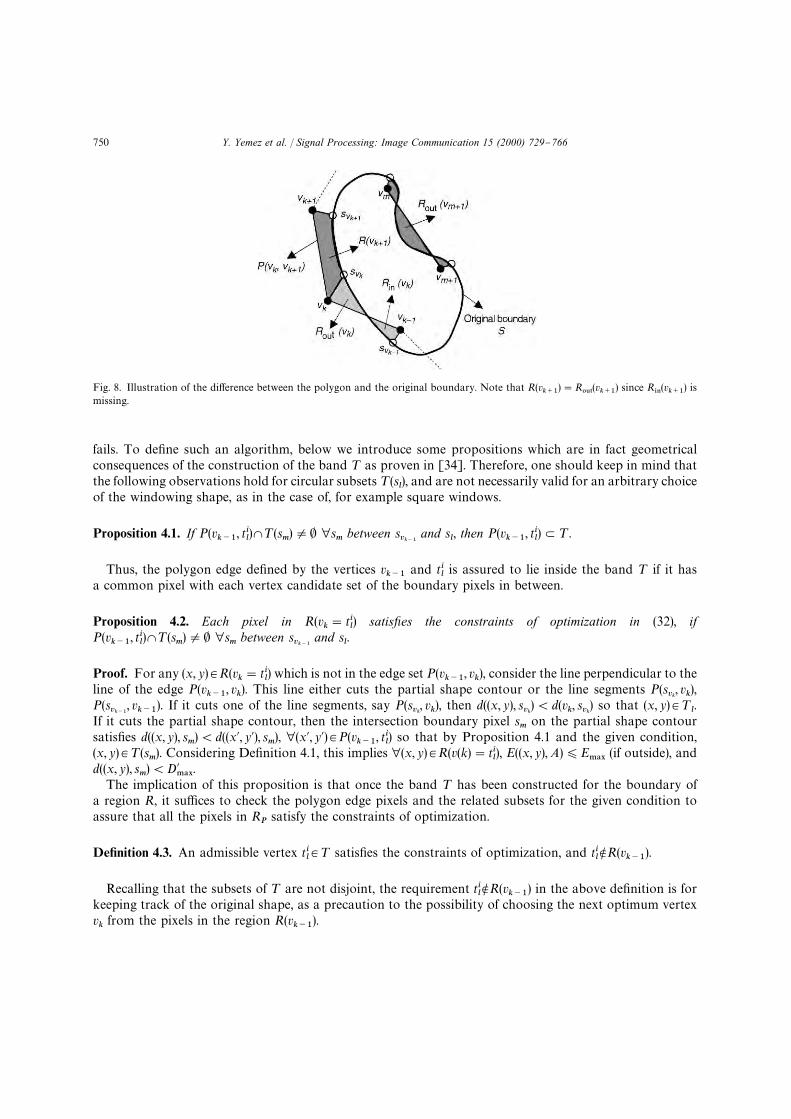
Fig. 8. Illustration of the di!erence between the polygon and the original boundary. Note that R(vk`1
)"R065
(vk`1
) since R*/(v
k`1) is
missing.
fails. To de"ne such an algorithm, below we introduce some propositions which are in fact geometricalconsequences of the construction of the band ¹ as proven in [34]. Therefore, one should keep in mind thatthe following observations hold for circular subsets ¹(s
l), and are not necessarily valid for an arbitrary choice
of the windowing shape, as in the case of, for example square windows.
Proposition 4.1. If P(vk~1
, til)W¹(s
m)O0 ∀s
mbetween s
vk~1and s
l, then P(v
k~1, ti
l)L¹.
Thus, the polygon edge de"ned by the vertices vk~1
and tilis assured to lie inside the band ¹ if it has
a common pixel with each vertex candidate set of the boundary pixels in between.
Proposition 4.2. Each pixel in R(vk"ti
l) satisxes the constraints of optimization in (32), if
P(vk~1
, til)W¹(s
m)O0 ∀s
mbetween s
vk~1and s
l.
Proof. For any (x, y)3R(vk"ti
l) which is not in the edge set P(v
k~1, v
k), consider the line perpendicular to the
line of the edge P(vk~1
, vk). This line either cuts the partial shape contour or the line segments P(s
vk, v
k),
P(svk~1
, vk~1
). If it cuts one of the line segments, say P(svk, v
k), then d((x, y), s
vk)(d(v
k, s
vk) so that (x, y)3¹
l.
If it cuts the partial shape contour, then the intersection boundary pixel sm
on the partial shape contoursatis"es d((x, y), s
m)(d((x@, y@), s
m), ∀(x@, y@)3P(v
k~1, ti
l) so that by Proposition 4.1 and the given condition,
(x, y)3¹(sm). Considering De"nition 4.1, this implies ∀(x, y)3R(v(k)"ti
l), E((x, y),A))E
.!9(if outside), and
d((x, y), sm)(D@
.!9.
The implication of this proposition is that once the band ¹ has been constructed for the boundary ofa region R, it su$ces to check the polygon edge pixels and the related subsets for the given condition toassure that all the pixels in R
Psatisfy the constraints of optimization.
De5nition 4.3. An admissible vertex til3¹ satis"es the constraints of optimization, and ti
lNR(v
k~1).
Recalling that the subsets of ¹ are not disjoint, the requirement tilNR(v
k~1) in the above de"nition is for
keeping track of the original shape, as a precaution to the possibility of choosing the next optimum vertexvkfrom the pixels in the region R(v
k~1).
750 Y. Yemez et al. / Signal Processing: Image Communication 15 (2000) 729}766

Proposition 4.3. If there exists no til3¹(s
l) such that ti
lis admissible then there exists no ti
m3¹(s
m) such that ti
mis
admissible for m'l.
The above proposition stands as a stopping rule for the shape polygonization algorithm. Thus thealgorithm does not necessarily visit all the boundary pixels, that is does not visit those remaining pixels thathave no potential to become a vertex.
Argument 4.1. If sl3S is the furthest possible boundary pixel from s
vk~1for which a ti
l3¹(s
l) is admissible, then
vHk
which is nearly optimum, is in ¹(sl).
When the admissible vertices are constrained so as to belong to the original boundary, i.e., D@.!9
"0 andD
.!9"0, the proof of the above argument is very straightforward. Since the vertices are coded di!erentially,
the optimization problem turns out to be "nding the shortest path between two boundary pixels under theimposed constraints. Thus the next optimum vertex is always the furthest possible boundary pixel, in view ofthe fact that the shortest path between two points is the line segment connecting them. However, whenD@
.!9A0, though rarely, the polygon can unnecessarily #uctuate from the original shape towards outside in
order to achieve the furthest sl. Meanwhile the optimum vertex, which can only be found by exhaustive
search which is computationally unfeasible, may indeed be in ¹m
such that m(l. This, in turn, may result ina higher bit-rate and in unnecessary distortions. A remedy for this undesired phenomenon is to constrain theadmissible vertices more strictly, by extending De"nition 4.3 as follows:
De5nition 4.4. A pixel til3¹ is an admissible vertex if and only if it complies with De"nition 4.3, and
moreover d(til, s
l))D
.!9.
It follows from the above de"nition that the polygon vertices are forced to be more faithful to the originalshape than the polygon edges which can be placed anywhere in the constructed band ¹. RecallingD@
.!9AD
.!9, the polygon vertices are chosen to be very close to the original boundary pixels s
l. In addition,
the second requirement of admissibility in De"nition 4.3 need not be checked when, for example, D.!9
"1 asin our implementations.
Argument 4.2. If til3¹(s
l) is admissible then vH
kOtj
l∀ j'i.
The above argument is a consequence of the pixel ordering, that is, if j'i then d(tjl, s
l)*d(ti
l, s
l). The
optimum vertex should be as faithful, i.e., close, as possible to the original shape for the sake of minimizingboth the bit-rate, i.e., the path length, and the shape distortion. A consequence of Argument 4.2 is also thatthere is no need to check all the vertex candidates in order to "nd the optimum vertex.
Let the initial vertex v1
be a point on the boundary, say s1, which is ideally chosen as to be the boundary
pixel with the largest curvature, and let NT(sj)
denote the number of pixels in the subset ¹(sj). In view of the
above discussion, given the vertex vk~1
associated to sl~1
, a nearly optimum vertex vkcan be found by the
following algorithm:
set vk"s
l;
for j"l to NS;
for i"1 to NT(sj)
;if ti
jis admissible (by De"nition 4.4)
set vk"ti
j;
break; (By Proposition 4.2)if v
khas not been set at iteration j break; (By Proposition 4.3)
Y. Yemez et al. / Signal Processing: Image Communication 15 (2000) 729}766 751

Due to Proposition 4.3, the algorithm does not necessarily visit all the boundary pixels; if a boundary pixelsjhaving no admissible vertex in ¹(s
j) is encountered, the iteration breaks. Similarly, all the vertex candidates
tijassociated to a boundary pixel s
jare not necessarily checked due to Proposition 4.2; if an admissible vertex
is found in ¹(sj), ignoring the remaining pixels, the iteration breaks and the algorithm proceeds with the next
boundary pixel sj`1
.
4.1.3. Summary of the coding algorithmThe proposed shape coding algorithm is actually straightforward although the description of its imple-
mentation seems to be complicated. The idea underlying the algorithm can be summarized as follows: Givenan optimum current vertex v
k~1, the next optimum vertex v
kis the furthest possible pixel which is in the close
neighborhood of the original shape, and which also satis"es the two constraints of the optimization. The "rstconstraint is that the geometric shape distortion of the resulting polygon edge P(v
k~1, v
k) should be less than
prede"ned values. These error thresholds are generally chosen to be smaller for the distortion towards insidethe region than that of the distortion towards outside, in order to avoid unlabeled ambiguous pixels. Thesecond constraint relates to the resulting synthesis error, given by the motion parameters. In other words, anoptimum vertex v
kis chosen such that the additional pixels imported into the region, denoted by R
065(v
k) in
Fig. 8, have to comply with the parameter A of the MC region within a synthesis error bound E.!9
. Once theband ¹ is constructed around the boundary shape as de"ned in De"nition 4.1, by Proposition 4.2 it su$cesto check whether each subset ¹(s
l) associated to the boundary pixels s
lbetween s
vk~1and s
vkintersects with the
polygon edge P(vk~1
, vk), in order to assure that the resulting polygon edge satis"es the constraints of the
optimization.
4.1.4. Vertex encodingThe vertices are coded di!erentially so that only the xy coordinate di!erences of the consecutive
vertices are considered. A maximum di!erence of 16 is allowed for each coordinate; if the di!erence is largerthan 16, then the vertex edge is partitioned into co-linear vertices. Moreover, due to the #exibility of placingthe vertices within a neighborhood, they can be chosen at pixels with only even (or odd) coordinates.Consequently, each vertex coordinate can be di!erentially coded with 4 bits, i.e., each vertex costs of 8 bitstotally.
Depending upon the value of D.!9
which determines the maximum tolerated shape distortion towardsinside, the shape coding process may result in unlabeled pixels in the segmentation, that is pixels notbelonging to any region R. These unlabeled pixels are assigned to the nearest R
i, which could be of model
compliance, model failure or background type. Conversely, due to the shape approximation, some pixelswhich may end up belonging to more than one region. Such ambiguous pixels are handled as follows: If oneof the multiple regions covering the ambiguous pixels is a model failure region, the pixel is assigned to thismodel failure region. If not, then the pixel is compensated by the associated motion parameter set of themodel compliance region whose boundary is the furthest from that pixel. Another possibility is to compen-sate the pixel by taking the average of the individual displacement vectors resulting from the motionparameters of the overlapping MC regions.
Two instances of the shape coding algorithm are illustrated in Fig. 9. One can notice that thepolygon approximation simpli"es the original contour by covering most of the concavities. In Fig. 10,the performance of the shape coding process is illustrated for whole segmentation maps resultingfrom two di!erent test sequences. The compression gain may di!er mainly depending upon the com-plexity and the context of the original contour. The average bit expenditures have come out to be 0.87 and0.96 bits per contour point for Miss America and Carphone sequences, respectively. These "gures, however,drop to 0.74 and 0.82 bits per contour point if only the shape coding of model compliance regions isconsidered.
752 Y. Yemez et al. / Signal Processing: Image Communication 15 (2000) 729}766

Fig. 9. Instances of the shape coding algorithm. The original contours of 220 and 241 pixels in the illustrations (a) and (b) areapproximated by 16 and 20 vertices, respectively.
4.2. Color coding
E$cient coding of color of the MF objects is an important problem in object-oriented coding schemes.Classical block-based coding methods relying on DCT are not very convenient, since the resulting regions tobe coded are arbitrarily shaped, and hence many blocks will have a hybrid support, that is partly MF andpartly non-MF.
One solution to the coding of arbitrarily shaped regions is the region-based DCT transform coding,proposed by Gilge et al. [9]. The transform utilized in this technique is based on two-dimensional DCT basefunctions which are orthonormal with respect to the region of support. In [32], an approximate shape-adaptive technique has been proposed, which is based on prede"ned orthogonal base functions and does notrequire any orthogonalization, but in turn it is not statistically optimum. The advantage of this technique isits low computational complexity compared to the region-based DCT transform in [9].
Another solution to the problem of color coding in object-oriented schemes has been proposed in [29],which is based on a hybrid-adaptive DCT/DPCM scheme. The arbitrarily shaped region is split into blockssome of which are not complete, i.e., consist of pixels belonging to the outside of the region. The idea is thatthe sparse blocks which mostly consist of outside pixels can be coded more e$ciently via DPCM coding. Onthe other hand, for the blocks which are almost complete, block-based DCT can be utilized to better exploitthe spatial correlation.
Since the hybrid DCT/DPCM coding is more e$cient compared to those in [9,32], we chose the hybridDCT/DPCM method for our object-oriented coding scheme. Both DCT and DPCM coding techniques areapplied to all blocks of each object separately for luminance and chrominance pixels. The method resulting ina shorter bit-stream is selected, assuring constant quality and "xed DCT and DPCM quantization step sizesfor all the blocks of an object as in [29].
Y. Yemez et al. / Signal Processing: Image Communication 15 (2000) 729}766 753

Fig. 10. Original and coded segmentation maps; Miss America (left), Carphone (right). In the above pair the bit expenditure for losslesschain coding is given, while in the "gures below the bit total corresponds to the number of vertices ]8.
4.3. Motion parameter coding
The motion of each object i is represented by a parameter set of m"12 coe$cients,A
i"Ma
1,2, a
6, b
1,2, b
6N. However, the resulting coe$cients have varying contributions in reducing the
prediction (compensation) error, hence the coe$cients with negligible contribution can be eliminated fromthe set A
ito obtain a reduced set of parameters AI
i. Some of the base functions Mx2, y2, xy,x, y, 1N can be
eliminated by checking the resulting additional prediction error. We use the coe$cient removal procedure of[16], which is based on the elimination of the coe$cients one by one, starting from those with higher degreeterms. For each parameter set AI
iwhich is initially set to A
i, the algorithm is as follows:
1. Find E.*/
"E(Ri, AI
i).
2. Remove a coe$cient and its associated base function from the set AIi.
3. Minimize E(Ri,AI
i) and determine the minimum value EI
.*/, via the method used for region merging.
4. If DE.*/
!EI.*/
D(e, replace the removed coe$cient and the associated base function.5. Iterate steps 1, 2, 3 and 4 for each coe$cient.
The motion estimation procedure of Section 2 results in real-valued coe$cients which have to bequantized and converted into a bit-stream. Prior to the estimation, the coordinates of the bounding box ofeach region are normalized to [!1, 1]][!1, 1] so that the coe$cients A
iare all in the same range. Thus,
a uniform quantizer can be designed adaptively, again by checking the resulting e!ect of the quantization onthe prediction error. The region scaling factor need not be transmitted since it can be deduced from the shapeinformation which is also available at the receiver.
754 Y. Yemez et al. / Signal Processing: Image Communication 15 (2000) 729}766

The eliminated coe$cients can be coded with a single #ag bit. The nonzero coe$cients which areconcentrated around zero, are coded with eight bits, 7 bits for the quantizer and one bit for the sign #ag.Three bits are spent to switch between eight di!erent quantizer step sizes. The rest of the nonzero coe$cientsare coded by a code length of 15}20 bits.
The coe$cient removal procedure not only reduces the bit budget, but also eliminates the error due to thequantization of small valued coe$cients, since the procedure iteratively updates the remaining nonzerocoe$cients. The above-described motion parameter coding method yields nearly optimum experimentalresults which will be presented in the next section.
5. Experimental results
The performance of the proposed approach has been tested on the well-known test sequences MissAmerica, Claire, Carphone and Foreman in the QCIF format. Miss America and Claire sequences are typicalvideo-telephony sequences with relatively small motion and stationary background, whereas Carphone andForeman sequences contain more severe motion, moving background and tilting of the camera. Eachsequence of 100 frames with the original frame rate 30 fr/s has been frameskipped by 6 so that the resultingsequence becomes sampled at the rate 5 fr/s. Though only the motion estimation-segmentation data istransmitted for every "fth frame, the motion information of the skipped frames has been also incorporated bythe multiframe analysis to improve the estimation-segmentation performance.
The quality performance of the coding scheme is illustrated in Figs. 11}14 at di!erent bit-rates. Bit-rateadjustment is obtained by tuning two main parameters of the segmentation scheme. The "rst parameter is themaximum allowed mean square error ¹
MCfor the model compliance regions, which mainly determines the
number of resulting MC regions and the size of model failure regions. The threshold ¹MC
has been chosen tovary in the range between 20 and 80 in our experiments. The MC regions have been coded only by their shapeand motion parameters, neglecting the errors resulting from motion modeling. The second parameter is theconstant quality required for color coding of the model failure regions, which varies between 33 and 36 dB. Inall the experiments, the minimum allowed size in pixel count for the model failure has been set to 20, in ordernot to cause disturbing distortions in the small, but semantically important parts of the scene such as eyesand mouth, whereas the minimum size for the model compliance regions has been chosen so as to varybetween 50 and 100.
Examples for the resulting segmentation maps, which illustrate the object di!erentiation capability of thescheme at di!erent bit-rates, are displayed in Figs. 15}18, where the darkest regions, the white regions and thegray regions correspond to model failure, background and model compliance regions, respectively. Theseexamples re#ect the semantics of the scene satisfactorily. To give an idea or justify the region growing step inthe motion segmentation algorithm the following pixel exchange tra$c can be quoted. The averagepercentages of the exchanged pixels with respect to the QCIF size as a result of the region growing process inSection 3.2, have come out to be 5% between MC regions, and 7% between MC and MF regions for the MissAmerica sequence, whereas these percentages have been respectively 12% and 17% for the Carphonesequence.
Figs. 11 and 12 show that the quality of the coded sequences are quite good even at very low bit-rates forMiss America and Claire sequences, although there seem to exist small distortions at 16 kbit/s. The initialframes of Claire and Miss America sequences have been coded by intra-frame coding, however the overheadof intraframe coding is not included in the displayed results. On the other hand, the resulting bit-rates forCarphone and Foreman sequences are comparatively larger, and the quality of the coded frames deterioratesas the bit-rate decreases towards modem speeds. The evidence for this deterioration can be observed in theresults given in Tables 1}4, where the total size of model failure regions comes out to be much smaller forMiss America and Claire sequences as compared to those sequences with more severe motion, with
Y. Yemez et al. / Signal Processing: Image Communication 15 (2000) 729}766 755

Fig. 11. Coder performance for Miss America sequence at di!erent bit-rates. In the order from top to down, original frames and codedframes at 37, 23 and 16 kbit/s, respectively.
756 Y. Yemez et al. / Signal Processing: Image Communication 15 (2000) 729}766

Fig. 12. Coder performance for Claire sequence at di!erent bit-rates. In the order from top to down, original frames and coded framesat 36, 28 and 17 kbit/s, respectively.
Y. Yemez et al. / Signal Processing: Image Communication 15 (2000) 729}766 757

Fig. 13. Coder performance for Carphone sequence at di!erent bit-rates. In the order from top to down, original frames and codedframes at 79 and 50 kbit/s, respectively.
proportional increases in the cost of color coding. Moreover, the number of MC regions for Foreman andCarphone sequences is a lot larger due to the nonstationary background, which in turn makes motion andshape coding more expensive.
Displayed segmentation maps in Figs. 17 and 18 show that there may exist many spurious model failureregions which are mainly due to sharp spatial changes where small displacement errors, which are notperceptually important, lead to very large synthesis errors. Thus, one can expect that elimination of thesespurious MF regions, would cause signi"cant decrease in the associated coding cost.
In order to illustrate the e$ciency of our motion parameter coding scheme, the entropy of the motioncoe$cients AI
i(i.e., after pruning with zeros) and the resulting average codeword lengths for di!erent
sequences are given in Table 5. Our average codeword lengths are within 10% of the correspondingentropies, that is the motion parameter coding scheme is close to the optimum. It is also as expected butinteresting to observe that the entropies of the motion parameters get larger as the motion in the scenebecomes more severe. The ratio of the number of removed zero coe$cients to the total number of coe$cientsis also included in Table 5. Let us point out that removal of coe$cients corresponds to the simpli"cation of
758 Y. Yemez et al. / Signal Processing: Image Communication 15 (2000) 729}766

Fig. 14. Coder performance for Foreman sequence at di!erent bit-rates. In the order from top to down, original frames and codedframes at 100 and 65 kbit/s, respectively.
the motion model; for example if the coe$cients of the second-order terms are all removed, the modelbecomes an a$ne case. The last column of Table 5 implies that the full quadratic model is needed intwo-thirds of the time while in one-third of the cases simpler models can be used.
We illustrate how the performance of the coding scheme changes in time by Figs. 19 and 20, where thepercentage of MF regions and the PSNR values for Miss America, Claire, Carphone and Foremansequences, are displayed as a function of time at 23, 28, 79 and 65 kbit/s, respectively. Carphone and Foremangraphs in Fig. 19 reveal that there may be #uctuations in the percentage of MF regions over time.
Simulation results indicate that the subjective quality is better than that of the schemes that rely on spatialsegmentation [27,3]. The reason is that in these contour-texture coding schemes, the emphasis is on theproblem of object tracking, giving relatively less importance to the resulting quality. The performance re-mains very dependent on the accuracy of the spatial segmentation, which in turn also necessitates a consider-able e!ort and bit budget for the compensation of the contour prediction errors resulting from the projection.
We have also performed experiments in order to justify the use of quadratic model vis-a-vis a$ne motionmodel. The motion estimation scheme, the decision criteria employed during the segmentation phase, and the
Y. Yemez et al. / Signal Processing: Image Communication 15 (2000) 729}766 759

Fig. 15. Polygonized segmentation maps of Miss America sequence at 16 kbit/s (the "rst row) and 23 kbit/s (the second row).
Fig. 16. Polygonized segmentation maps of Claire sequence at 17 kbit/s (the "rst row) and 28 kbit/s (the second row).
parameter coding strategy have all been kept the same for both cases. The only di!erence was that the a$nemodel had only six parameters to be estimated and the coe$cients of the second-order terms were assumedto be zero. During the experiments, we have observed that a$ne modeling may sometimes lead to a bettermotion representation for an object region, depending upon the size, the true motion, and the surfacegeometry of the region. This is actually due to the fact that the dimension of the optimization problem ina$ne case is smaller than that of the quadratic model, which in turn reduces the complexity and increases therobustness of the optimization. Thus, in order to make use of a$ne modeling in the cases where it is moreappropriate for motion modeling compared to quadratic transform, we have employed a joint strategy sothat during the motion estimation-segmentation scheme, both a$ne and quadratic modeling have beenconsidered and accomplished separately for each motion estimation, and the one which results in a smallermean squared error has been chosen as the model of that coding instant. Recall that in the previous
760 Y. Yemez et al. / Signal Processing: Image Communication 15 (2000) 729}766
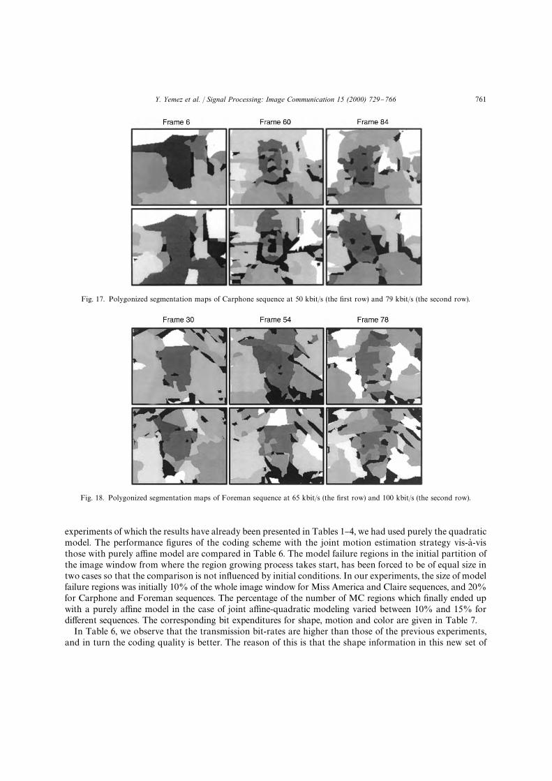
Fig. 17. Polygonized segmentation maps of Carphone sequence at 50 kbit/s (the "rst row) and 79 kbit/s (the second row).
Fig. 18. Polygonized segmentation maps of Foreman sequence at 65 kbit/s (the "rst row) and 100 kbit/s (the second row).
experiments of which the results have already been presented in Tables 1}4, we had used purely the quadraticmodel. The performance "gures of the coding scheme with the joint motion estimation strategy vis-a-visthose with purely a$ne model are compared in Table 6. The model failure regions in the initial partition ofthe image window from where the region growing process takes start, has been forced to be of equal size intwo cases so that the comparison is not in#uenced by initial conditions. In our experiments, the size of modelfailure regions was initially 10% of the whole image window for Miss America and Claire sequences, and 20%for Carphone and Foreman sequences. The percentage of the number of MC regions which "nally ended upwith a purely a$ne model in the case of joint a$ne-quadratic modeling varied between 10% and 15% fordi!erent sequences. The corresponding bit expenditures for shape, motion and color are given in Table 7.
In Table 6, we observe that the transmission bit-rates are higher than those of the previous experiments,and in turn the coding quality is better. The reason of this is that the shape information in this new set of
Y. Yemez et al. / Signal Processing: Image Communication 15 (2000) 729}766 761

Table 1Quantitative performance "gures of the coding scheme for Miss America sequence at 5 fr/s (average values per frame). The bit-rate canbe found by the sum of shape, motion and color bit expenditures multiplied by the frame rate
Bit-rate Shape Motion Color MC MF PSNR(kbit/s) (bit) (bit) (bit) (number) (% size) (dB)
16 1456 594 1070 9 1.4 34.723 1616 560 2292 8 2.7 35.637 1893 736 4637 10 6.1 36.2
Table 2Quantitative performance "gures of the coding scheme for Claire sequence
Bit-rate Shape Motion Color MC MF PSNR(kbit/s) (bit) (bit) (bit) (number) (% size) (dB)
17 1281 628 1397 9 1.5 34.828 1774 876 2800 12 2.6 36.336 1773 887 4486 12 4.3 37.3
Table 3Quantitative performance "gures of the coding scheme for Carphone sequence
Bit-rate Shape Motion Color MC MF PSNR(kbit/s) (bit) (bit) (bit) (number) (% size) (dB)
50 3856 1866 4100 25 4.9 29.779 4165 1894 9375 25 10.3 31.5
Table 4Quantitative performance "gures of the coding scheme for Foreman sequence
Bit-rate Shape Motion Color MC MF PSNR(kbit/s) (bit) (bit) (bit) (number) (% size) (dB)
65 3895 1899 6955 24 8.6 30100 4426 2037 13179 26 14.6 31.2
Table 5E$ciency of the motion parameter coding scheme: entropy and resulting average bit-lengths for the 12 quadratic motion parameters,and percentage of the removed coe$cients
Sequence Entropy Average bit length Removed coe$cients
Miss America 5.25 5.81 37%Claire 5.48 5.97 37%Carphone 5.76 6.21 33%Foreman 6.00 6.66 29%
762 Y. Yemez et al. / Signal Processing: Image Communication 15 (2000) 729}766

Fig. 19. MF region sizes in individual frames, as a percentage of the QCIF size.
Fig. 20. PSNR values for individual frames.
experiments has been coded with a higher precision in order to have a more accurate comparison which is asfree as possible of errors that may result from shape approximation and elimination of very small regions.The PSNR "gures achieve an improvement of 0.7 dB in performance for Miss America and Foremansequences, and 0.4 dB for Claire and Carphone sequences. We should remind that the PSNR value for eachimage is calculated over the whole frame. Thus although the PSNR improvements seem small, theycorrespond to regions or objects of the scene for which the motion can be modeled better by a second-ordermodel. The cost of this improvement in PSNR "gures is the slight increase in the resulting bit-rates whichoriginates from the additional coding load of the second-order motion model parameters as observed inTable 7. However, this additional cost is tolerable for the resulting PSNR improvements.
Y. Yemez et al. / Signal Processing: Image Communication 15 (2000) 729}766 763

Table 6Comparison of the performance "gures of the coding scheme for purely a$ne and joint a$ne-quadratic motion estimation
Purely a$ne Joint a$ne-quadratic
Sequence Bit-rate MC MF PSNR Bit-rate MC MF PSNR(kbit/s) (number) (% size) (dB) (kbit/s) (number) (% size) (dB)
Miss America 37.9 16.4 4.6 36.8 38.6 17.2 4.2 36.9Claire 35.5 17.1 3.1 37.3 38.0 17.6 3.0 37.5Carphone 78.9 38.5 7.2 32.9 80.6 41.9 6.3 33.4Foreman 108.5 48.7 14.3 32.1 110.2 50.5 12.1 32.2
Table 7Bit expenditures per frame for purely a$ne and joint a$ne-quadratic motion estimation
Purely a$ne Joint a$ne-quadratic
Sequence Bit-rate Motion Shape Color Bit-rate Motion Shape Color(kbit/s) (bits) (bits) (bits) (kbit/s) (bits) (bits) (bits)
Miss America 37.9 558 3257 3775 38.6 954 3320 3452Claire 35.5 622 3082 3404 38.0 1339 3116 3149Carphone 78.9 1369 8457 5963 80.6 2608 8223 5294Foreman 108.5 1965 9485 9995 110.2 3440 9604 8600
6. Conclusions
A novel video coding scheme, in the VLBR range, has been advanced, that exploits the temporalredundancy by a combination of quadratic motion modeling, region growing segmentation and an e$cientpolygonization scheme. The result is an object-oriented coding scheme, whose advantages and novelties canbe summarized as follows:1. The segmentation problem is formulated as an optimization problem aiming to "nd the optimal
description of the scene in the rate-distortion sense in terms of model compliance and model failure objectsde"ned with their motion, shape and color parameters. This de"nes a joint problem of motion estimationand segmentation, which has been solved near optimally via an iterative procedure.
2. The object hierarchy [14,4] has been inverted in the sense that the segmentation proceeds from smallerobjects to larger ones. By making use of the motion parameters estimated interactively with thesegmentation process, a region growing process is started which iteratively rede"nes the object boundariesand enlarges the initial object seed blocks. The reversed hierarchy and region growing process result ina more #exible segmentation scheme as compared to those in [14,4], by being able to identify more genericmotion segments. Thus it is applicable to image sequences of any content, i.e., not necessarily limited tohead-and-shoulder scenes.
3. The object motion is represented by the quadratic transform model [16,4], which is a more general andtherefore #exible polynomial model as compared to the other lower order polynomial representations,namely the translation and the a$ne transformation. Quadratic transform provides a representation forthe rigid motion and linear deformation of objects with quadratic facets, thus avails us of the possibility toobtain an accurate motion modeling for larger and more complex objects, which is favorable for bothcoding cost and quality considerations.
764 Y. Yemez et al. / Signal Processing: Image Communication 15 (2000) 729}766

4. The performance of quasi-Newton estimation of the quadratic transform coe$cients is improved bya combined multiresolution and multiframe analysis. The motion information in the skipped frames isincorporated so that the motion parameters evolve temporally. The multiframe analysis tends to increasethe coherency of the objects resulting from the motion segmentation with the true objects, hence betterobject tracking can be realized.
5. E$cient coding of the object shape is crucial since object-oriented methods have to allocate a considerablepart of the available bit budget for shape representation unlike the block-based coders such as H.263. Inthis work, a context-base shape coding technique is proposed. The context-based denotes here the factthat the shape coding takes into account not only the geometric shape distortion, but also the imagesynthesis error. In other words, during the shape coding process, the segmentation map is reconsideredand re"ned so that spurious details of the map are omitted to achieve a more e$cient coding.
In conclusion, a complete object-oriented codec has been proposed. Further issues to be addressed in futureresearch list as follows:
The quality performance of our codec is quite good at very low bit-rates when applied to image sequenceswith limited motion content as in Claire and Miss America sequences. However, the size of model failureregions and the number of model compliance regions increase, as in the case of Foreman and Carphonesequences, the performance deteriorates disturbingly at the very low bit-rates, or alternatively, for satisfac-tory quality higher speeds are needed. Simulation results show that a considerable part of the bit budget mustbe allocated to the shape information in this case.
The shape coding e$ciency can be further improved by executing the shape coding algorithm simulta-neously for each object region in the scene. This puzzle tree organization of regions can be more advantage-ous in reducing shape redundancy by coding the common boundaries only once.
A second avenue of improvement could be the use of so called Voronoi or Dirichlet diagrams [1,2,20],which can e$ciently be utilized in the object tracking problem. A Voronoi diagram is a construct of imagepoints each of which de"nes a convex polygonal territory which is the region of the image plane nearer to itthan to any other data point. Such a representation corresponds to a diagram of neighboring regions whichcan easily be modi"ed by adding or deleting points. Thus, in the context of object-oriented video coding, itcan be utilized for the representation of a segmentation map at di!erent resolution levels and for itsmodi"cation so as to adapt to the temporal changes in the scene. Once a Voronoi diagram is constructed forthe initial frame, the de"ning points (the seeds) can be projected to the consecutive frames via estimatedmotion parameters so that the projected points de"ne a new segmentation map, which then can be modi"edby adding or deleting points mainly at the object boundaries. The mapping of a Voronoi diagram is quiterobust, which does not yield ambiguous or con#icting pixels, or nonconvex overlapping regions. Thus ourpixelwise region growing technique can be extended so as to proceed more smoothly in terms of Voronoipolygons, resulting hopefully in regions with less spurious details.
References
[1] E. Bertin, H. Bischof, P. Bertolino, Voronoi pyramids controlled by Hop"eld neural networks, Comput. Vision Image Under-standing 63 (3) (1996) 462}475.
[2] A. Bowyer, Computing Dirichlet tessellations, Comput. J 24 (2) (1981) 162}166.[3] P. Brigger, Morphological shape representation using the skeleton decomposition: application to image coding, Ph.D. Disserta-
tion, Ecole Polytech. Federale de Lausanne, These No 1448, 1995.[4] N. Diehl, Object-oriented motion estimation and segmentation in image sequences, Signal Processing: Image Communication
3 (1991) 23}56.[5] J.-L. Dugelay, H. Sanson, Di!erential methods for the identi"cation of 2D and 3D motion models in image sequences, Signal
Processing: Image Communication 7 (1995) 105}127.[6] M. Eden, M. Kocher, On the performance of a contour coding algorithm in the context of image coding. Part I: Contour segment
coding, Signal Processing 8 (1985) 381}386.
Y. Yemez et al. / Signal Processing: Image Communication 15 (2000) 729}766 765

[7] R. Fletcher, Practical Methods of Optimization, Wiley, New York, 1987.[8] H. Freeman, On the encoding of arbitrary geometric con"gurations, IRE Trans. Electron. Comput. EC-10 (1) (1961) 260}268.[9] M. Gilge, T. Engelhardt, R. Mehlan, Coding of arbitrarily shaped image segments based on a generalized orthogonal transform,
Signal Processing: Image Communication 1 (1989) 153}180.[10] C. Gu, M. Kunt, Very low bit-rate coding using multi-criterion segmentation, in: First IEEE International Conference on Image
Processing, Vol. 2, 1994, pp. 418}422.[11] R.M. Haralick, S.R. Sternberg, X. Zhuang, Image analysis using mathematical morphology, IEEE Trans. Pattern Anal. Mach.
Intell. 9 (4) (1987) 532}549.[12] M. HoK tter, Object-oriented analysis}synthesis coder based on moving two-dimensional objects, Signal Processing: Image
Communication 2 (4) (1990) 409}428.[13] M. HoK tter, Predictive contour coding for an object-oriented analysis-synthesis coder, in: IEEE International Symposium on
Information Theory, 1990, p. 75.[14] M. HoK tter, R. Thoma, Image segmentation based on object oriented mapping parameter estimation, Signal Processing 15 (3)
(1988) 315}334.[15] S. Jeannin, On the combination of a polynomial motion estimation with a hierarchical segmentation based video coding scheme,
in: IEEE International Conference on Image Processing, Lausanne, Vol. 2, 1996, pp. 489}492.[16] M. Karczewicz, J. Nieweglowski, P. Haavisto, Motion estimation and representation for arbitrarily shaped image regions, in:
IEEE International Conference on Image Processing, Vol. 2, 1995, pp. 197}200.[17] M. Kunt, A. Ikonomopoulos, M. Kocher, Second generation image coding techniques, Proc. IEEE 73 (1985) 549}575.[18] F. Marques, P. Brigger, A. Gasull, C. Gu, F. Meyer, C. Oddou, Contour coding, Tech. Rep., Universitat Polytecnica de Barcelona
(UPC), 1993.[19] F. Marques, P. Salembier, M. Pardas, R. Morros, I. Corset, S. Jeannin, B. Marcotegui, F. Meyer, A segmentation-based coding
system allowing manipulation of objects (SESAME), in: IEEE International Conference on Image Processing, Lausanne, Vol. 2,1996, pp. 121}124.
[20] A. Montanvert, P. Meer, A. Rosenfeld, Hierarchical image analysis using irregular tessellations, IEEE Trans. Pattern Anal. Mach.Intell. 13 (4) (1991) 307}316.
[21] H.G. Musmann, M. HoK tter, J. Ostermann, Object-oriented analysis}synthesis coding of moving images, Signal Processing: ImageCommunication 1 (2) (1989) 117}138.
[22] Y. Nakaya, H. Harashima, Motion compensation based on spatial transformations, IEEE Trans. Circuits Systems Video Technol.4 (3) (1994) 339}356.
[23] J. Ostermann, Object-based analysis-synthesis coding (OBASC) based on the source model of moving #exible 3-D objects, IEEETrans. Image Processing 3 (5) (1994) 705}711.
[24] F. Pereira, R. Koenen, Requirements and applications for MPEG 4, Tech. Rep. 711, ISO/IEC JTC1/SC29/WG 11, 1994.[25] W.H. Press, B.P. Flannery, S.A. Teulosky, W.T. Vetterling, Numerical Recipes in C, Cambridge University Press, Cambridge, 1988.[26] P. Salembier, M. Pardas, Hierarchical morphological segmentation for image sequence coding, IEEE Trans. Image Processing
3 (5) (1994) 639}651.[27] P. Salembier, L. Torres, F. Meyer, C. Gu, Region-based video coding using mathematical morphology, Proc. IEEE 83 (6) (1995)
843}857.[28] H. Sanson, Joint estimation and segmentation of motion for video coding at low bit-rates, in: COST 211ter European Workshop
on New Techniques for Coding of Video Signals at very Low Bitrates, 1993, Paper 4.4.[29] H. Schiller, M. HoK tter, Investigations on colour coding in an object-oriented analysis}synthesis coder, Signal Processing: Image
Communication 5 (1993) 319}326.[30] G.M. Schuster, A.K. Katsaggelos, An optimal lossy segmentation encoding scheme, in: Proceedings of the Conference on Visual
Communication and Image Processing, Vol. 2727, 1996, pp. 1050}1061.[31] G.M. Schuster, A.K. Katsaggelos, An e$cient boundary encoding scheme which is optimal in the rate distortion sense, in: IEEE
International Conference on Image Processing, Lausanne, Vol. 2, 1996, pp. 77}80.[32] T. Sikora, Low complexity shape-adaptive DCT for coding of arbitrarily shaped image segments, Signal Processing: Image
Communication 7 (1995) 381}395.[33] P. Willemin, T. Reed, M. Kunt, Image sequence coding by split and merge, IEEE Trans. Communication 39 (12) (1991) 1845}1855.[34] Y. Yemez, Object-oriented video coding based on region growing motion segmentation, Ph.D. Dissertation, Electrical and
Electronics Eng. Dep., Bogy azic7 i University, 1997.[35] Y. Yemez, B. Sankur, E. Anarmm, Region growing motion segmentation and estimation in object-oriented video coding, in: IEEE
International Conference on Image Processing, Lausanne, Vol. 2, 1996, pp. 521}524.[36] Y. Yemez, B. Sankur, E. Anarmm, An object-oriented video codec based on region growing motion segmentation, in: IEEE
International Conference on Image Processing, 1997, pp. 444}447.
766 Y. Yemez et al. / Signal Processing: Image Communication 15 (2000) 729}766