a primer on control systems - restek · a passive control system. open loop control systems have...
TRANSCRIPT

AbstractA comprehensive discussion of control system theory would best be handled not by a discrete text, but by a small library of techni-cal publications. This article is not meant to be comprehensive, but rather to provide a practical overview of the topic. It will not discuss system design in any capacity; however, it will present sufficient information to quickly develop a cursory understanding of fundamental control system terminology and concepts.
IntroductionA control system is a means used to manipulate a process. The process could exist in various forms, as mechanical, electrical, chemical, or computational systems as in the case of a mathematical model. A control system consists of both a device, known as a controller, and a method used to regulate the behavior of a specific component of the process. The component being manipulated is known as the process variable. For the purposes of this technical brief, the process variable will be gas flow.
Like the various processes it controls, the controller itself could exist in various forms. It could be a mechanical device, an electrical circuit, a computer, or a combination of these forms. In the case of gas flow control, the controller is usually some type of valve. The control variable is the component of the controller that determines the extent to which the process variable is manipulated. In this case, the control variable represents the opening of the valve. The way that a control variable is manipulated is determined by the control method.
For instance, using a proportional valve, gas flow could be manipulated by the size of the valve opening. Using an on-off valve, this is not possible since the valve can only be fully open or closed. In this case, the flow must be manipulated by varying the ratio of open to closed durations of the valve. The purpose of manipulation of a process variable by a controller is to influence the variable to conform to a specific state called the setpoint. In the preceding example, the setpoint is the rate of flow.
System ClassificationsThere are two fundamental classes of control systems. The first is an open loop control system, which is sometimes referred to as a passive control system. Open loop control systems have the ability to control, but not sense the process variable. These systems blindly control the process variable without any reference to a setpoint.
The second class is a closed loop control system, sometimes referred to as an active control system. Closed loop control systems have both the ability to control and sense the process variable. This is accomplished through the use of feedback. Using feedback, a closed loop control system can sense when a process variable differs from the setpoint, and it will use a prescribed method to modify the control variable in a way that influences the process variable towards the setpoint.
In order to better understand these types of control systems, consider some simple examples based on heating a house. In this case, the current house temperature is the process variable and the desired house temperature is the setpoint.
Technical Article
A Primer on Control SystemsBy Brandon Tarr, Electro-Mechanical Design Engineer
www.restek.comInnovative Chromatography Products
www.restek.com 2
One way to heat a house is by using a fireplace. This is a good example of an open loop control system. Here, the heat produced by the fire is the control variable. As stated previously, open loop control systems cannot utilize a setpoint. Hence, there is no way to enter a desired house temperature into a fireplace. The size of the fire can be changed by adding or removing logs, but the fireplace cannot reference a setpoint or adjust its output.
Another way to heat a house is with a furnace. This is a good example of a closed loop control system. Here, the heat produced by the furnace is the control variable. The furnace is able to simultaneously sense both the process variable (current house temperature) and the setpoint (desired house temperature) through the thermostat and adjust its output accordingly.
Control ParametersA control system is a combination of both a device and a method used to regulate the behavior of a process variable. While an open loop system only has a single method of control, closed loop systems can have various methods of control.
In the example of the furnace-based house heating control system, notice that the type of furnace was not specified. There are many types of furnaces that use different control methods.
For example, a residential forced air oil furnace can only output air at a fixed temperature and at a fixed rate of flow. In this case, if the process variable is below the setpoint, the control system will attempt to correct the situation by changing the control variable. The furnace only has two possible states of the control variable, on or off. This type of closed loop control system utilizes a method called on-off control.
On-off control systems typically do not provide precise control of a process variable. In the previous example, when the thermostat measures a house temperature that is equal to the setpoint, it notifies the furnace that the call for heat is complete. The furnace then begins a cool down cycle; it will continue to output airflow until this cycle is complete. Often, this causes the process variable to go above the setpoint. This is called overshoot.
Similarly, when the house cools to the setpoint, the thermostat turns on the furnace. By the time the furnace heats up and begins to deliver heat to the house, the actual process variable often drops below the setpoint. This is called undershoot.
Consider another furnace example involving a commercial gas furnace. Often, these furnaces have the ability to control either the temperature of the air that is output by varying the amount of gas to the flame, or the volume of air that is output by varying a mechanical damper. This control method is called proportional control. A proportionally controlled heating system is both more efficient and accurate than an on-off controlled heating system because it can vary the amount of heat that is output.
In general, heating control systems manipulate relatively sluggish process variables. Other control systems may manipulate very fast moving process variables and often require more precise control. Pressure and flow control systems are specific examples. Control systems for these types of process variables often employ yet another method of control called proportional-integral-derivative (PID) control.
While a detailed discussion of PID control systems is well beyond the scope of this document, a general overview is provided here. A PID control system employs an advanced control methodology that utilizes a series of independent control parameters. These parameters allow it to influence a process variable towards the setpoint very quickly and accurately. While in a purely theoretical sense the control parameters are magnitude scaling variables, or gain, in practice they are often interpreted in terms of time. If error is defined as the differential between the current value of the process variable and the setpoint, the parameters manage error in the following ways:
P - Present error I - Accumulation of past errors D - Prediction of future errors (based on current rate of change)
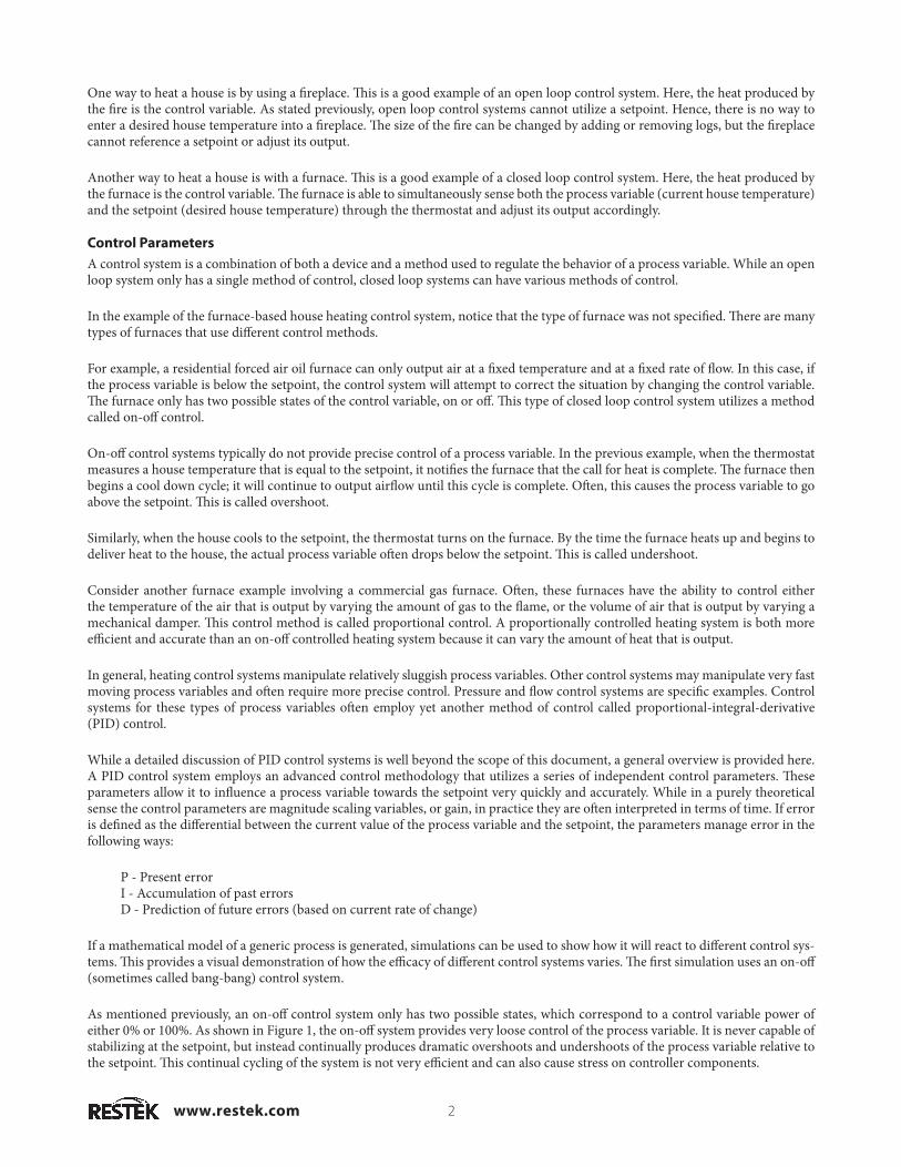
If a mathematical model of a generic process is generated, simulations can be used to show how it will react to different control sys-tems. This provides a visual demonstration of how the efficacy of different control systems varies. The first simulation uses an on-off (sometimes called bang-bang) control system.
As mentioned previously, an on-off control system only has two possible states, which correspond to a control variable power of either 0% or 100%. As shown in Figure 1, the on-off system provides very loose control of the process variable. It is never capable of stabilizing at the setpoint, but instead continually produces dramatic overshoots and undershoots of the process variable relative to the setpoint. This continual cycling of the system is not very efficient and can also cause stress on controller components.
www.restek.com3
Figure 1 On-off control system simulation.
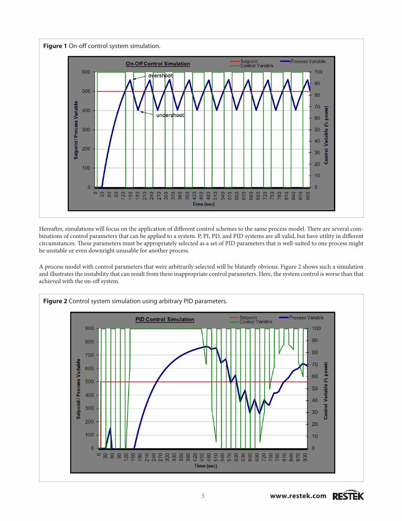
Figure 2 Control system simulation using arbitrary PID parameters.
Hereafter, simulations will focus on the application of different control schemes to the same process model. There are several com-binations of control parameters that can be applied to a system. P, PI, PD, and PID systems are all valid, but have utility in different circumstances. These parameters must be appropriately selected as a set of PID parameters that is well-suited to one process might be unstable or even downright unusable for another process.
A process model with control parameters that were arbitrarily selected will be blatantly obvious. Figure 2 shows such a simulation and illustrates the instability that can result from these inappropriate control parameters. Here, the system control is worse than that achieved with the on-off system.
www.restek.com 4
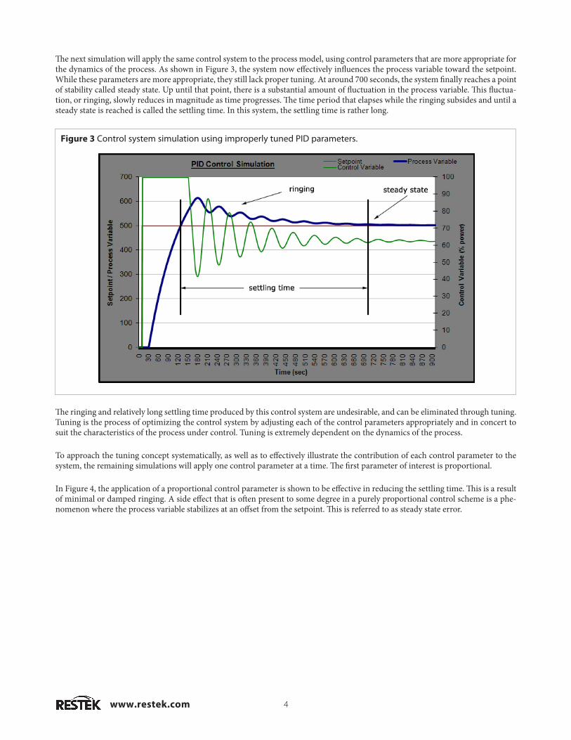
The next simulation will apply the same control system to the process model, using control parameters that are more appropriate for the dynamics of the process. As shown in Figure 3, the system now effectively influences the process variable toward the setpoint. While these parameters are more appropriate, they still lack proper tuning. At around 700 seconds, the system finally reaches a point of stability called steady state. Up until that point, there is a substantial amount of fluctuation in the process variable. This fluctua-tion, or ringing, slowly reduces in magnitude as time progresses. The time period that elapses while the ringing subsides and until a steady state is reached is called the settling time. In this system, the settling time is rather long.
Figure 3 Control system simulation using improperly tuned PID parameters.
The ringing and relatively long settling time produced by this control system are undesirable, and can be eliminated through tuning. Tuning is the process of optimizing the control system by adjusting each of the control parameters appropriately and in concert to suit the characteristics of the process under control. Tuning is extremely dependent on the dynamics of the process.
To approach the tuning concept systematically, as well as to effectively illustrate the contribution of each control parameter to the system, the remaining simulations will apply one control parameter at a time. The first parameter of interest is proportional.
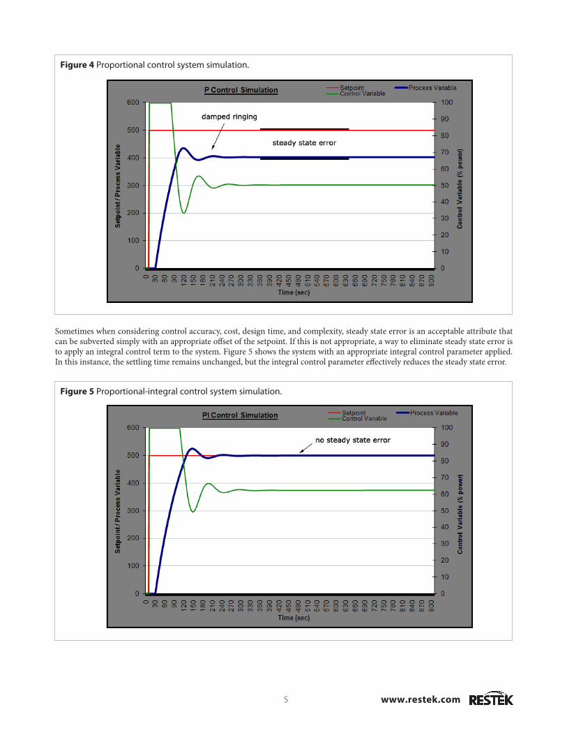
In Figure 4, the application of a proportional control parameter is shown to be effective in reducing the settling time. This is a result of minimal or damped ringing. A side effect that is often present to some degree in a purely proportional control scheme is a phe-nomenon where the process variable stabilizes at an offset from the setpoint. This is referred to as steady state error.
www.restek.com5
Figure 4 Proportional control system simulation.
Sometimes when considering control accuracy, cost, design time, and complexity, steady state error is an acceptable attribute that can be subverted simply with an appropriate offset of the setpoint. If this is not appropriate, a way to eliminate steady state error is to apply an integral control term to the system. Figure 5 shows the system with an appropriate integral control parameter applied. In this instance, the settling time remains unchanged, but the integral control parameter effectively reduces the steady state error.
Figure 5 Proportional-integral control system simulation.
www.restek.com 6
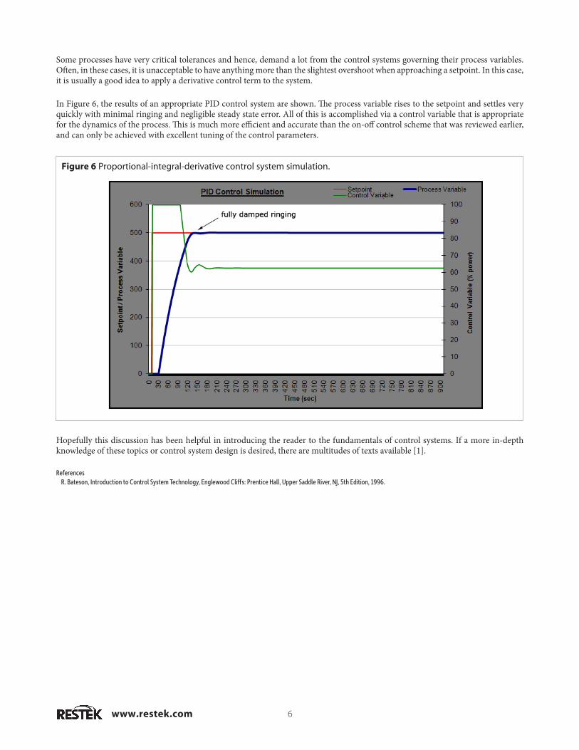
Some processes have very critical tolerances and hence, demand a lot from the control systems governing their process variables. Often, in these cases, it is unacceptable to have anything more than the slightest overshoot when approaching a setpoint. In this case, it is usually a good idea to apply a derivative control term to the system.
In Figure 6, the results of an appropriate PID control system are shown. The process variable rises to the setpoint and settles very quickly with minimal ringing and negligible steady state error. All of this is accomplished via a control variable that is appropriate for the dynamics of the process. This is much more efficient and accurate than the on-off control scheme that was reviewed earlier, and can only be achieved with excellent tuning of the control parameters.
Figure 6 Proportional-integral-derivative control system simulation.
Hopefully this discussion has been helpful in introducing the reader to the fundamentals of control systems. If a more in-depth knowledge of these topics or control system design is desired, there are multitudes of texts available [1].
References R. Bateson, Introduction to Control System Technology, Englewood Cliffs: Prentice Hall, Upper Saddle River, NJ, 5th Edition, 1996.
PATENTS & TRADEMARKSRestek patents and trademarks are the property of Restek Corporation. Other trademarks appearing in Restek literature or on its website are the property of their respective owners. The Restek registered trademarks used here are registered in the United States and may also be registered in other countries.
Restek U.S. • 110 Benner Circle • Bellefonte, PA 16823 • 814-353-1300 • 800-356-1688 • fax: 814-353-1309 • www.restek.comRestek France • phone: +33 (0)1 60 78 32 10 • fax: +33 (0)1 60 78 70 90 • e-mail: [email protected] GmbH • phone: +49 (0)6172 2797 0 • fax: +49 (0)6172 2797 77 • e-mail: [email protected] Ireland • phone: +44 (0)2890 814576 • fax: +44 (0)2890 814576 • e-mail: [email protected] Japan • phone: +81 (3)6459 0025 • fax: +81 (3)6459 0025 • e-mail: [email protected] Restek U.K. LTD • phone: +44 (0)1494 563377 • fax: +44 (0)1494 564990 • e-mail: [email protected]
Lit. Cat.# GNAN1401© 2011 Restek Corporation. All rights reserved.