a presentation to blow you away: wind turbine foundations · 2018-08-13 · rock anchors and cap...
TRANSCRIPT

A Presentation to Blow You Away:Wind Turbine Foundations
Kirk B. Morgan, P.E., P.Eng.
Senior Civil Engineer
Barr Engineering Co.
Overview
Foundation TypesMaterials
Market RegulationDesign Requirements
Design BriefFuture Developments

Foundation Types

BASEcase
Photo credits: Jenny Hager, Kirk Morgan

Spread Footing
• 50-70 ft across x 8-12 ft deep• Cast-in-Place• Robust

Rock Anchors and Cap
–Smaller excavation (30ft dia)–Anchors installation testing fatigue design corrosion protection long-term monitoring

Piles and Cap
• Costly• Cap dead weight• Soil / structure interaction• Stiffness offset issues• Pile steel fatigue design

Short Pier*
• 16-18+ ft diameter x 25-35 ft depth• Stiffness offset issues• Construction challenges• Economical
* Not the same as a rock socket foundation

Materials (US)spread foundations

materials –
concrete• 300 to 500 yds and more• 4500 to 6000 psi (typically 5000 psi)• ¾” to 1 ½” coarse aggregate• Entrained air per code• Fly Ash or GGBFS (less common)• ASR avoided (or sealers used)• site geotechnical can influence cement type

materials –
concrete
• standard cylinders• hot / cold weather concrete• mass concrete measures• workability not a concern with good practice• attention to curing in extreme conditions

materials –
reinforcing
• ASTM A615 60 and 75 ksi• deformed bars• #4 to #11 size
– #14 increasingly used; still not that common

materials –
anchor bolts
• ASTM A615 (fy = 75 ksi)• Custom (e.g. fy = 90 ksi)• ASTM A722 (fy = 120 ksi)• cold-formed threads
• common sizes 1 1/4” and 1 3/8”• sleeves (PVC, heat shrink)
• post-tensioned (80 to 100 kips)

materials –
alignment ring & embedment plate
• ASTM (A36, A529, A572, etc.)• 1 to 2 in thick• dimensions matching tower flange
typically

materials –
tower flange grout
• modified cementitious or epoxy• 8000 – 15000 psi• formed above or recessed• 1 ½ to 3 in thick• volume extended

Market Regulation

DOMESTIC >>>
EUROPEAN >>>
Standards Bodies / Codes
• International Code Council (ICC)– American Concrete Institute (ACI)
Committee 378 Concrete Towers
– American Institute of Steel Construction (AISC)• American National Standards Institute (ANSI)
– American Wind Energy Association (AWEA) Wind Standards Committee and Subcommittees
• International Electrotechnical Commission (IEC)– Technical Committee No. 88
• EN Eurocodes• CEB-FIP

• Finance
• Equity
• Transactions
Independent Engineers

• Projects
• Turbines
• Components– Blades– Towers– Foundations– Misc
Certification Bodies

Foundation Design Requirements

Performance Criteria
• Stability• Strength• Rotational Stiffness• Settlement• Durability• Economy
Photo credits:News-Gazette of Central Illinois, www.orkney.com

Foundation Design Requirements
ASCE/AWEA RP2011, Recommended Practice for Compliance of Large Land-BasedWind Turbine Support Structures
• “IEC 61400-1 Ed.3: Wind turbines – Part 1: Design requirements”
• FUTURE – “IEC 61400-6: Wind turbines – Part 6: Tower and foundation design requirements”
• ICC, “International Building Code”• CEB-FIP Model Code 1990• DNV, “Offshore Standard C502 Offshore Concrete Structures”• GL, “Guideline for the Certification of Wind Turbines”
US industry document(used outside US too)
US and International codes and standards

IEC Load Cases
• Operational• Start-up, shut-down, e-stop• Machine faults• Grid interaction• Extreme wind events• Combinations of the above

Probability Distribution for Wind Speed
Prob
abilit
y De
nsity
Wind speed (m/s)
0.00
0.02
0.04
0.06
0.08
0.10
0 5 10 15 20 25
From Guidelines for Design of Wind Turbines, 2nd Edition, DNV 2002 and Garrad Hassan and Partners, Bristol, U.K.
Hours per load case
0
2000
4000
6000
8000
10000
12000
\dlc
6.4\
3ms\
-8\
\dlc
6.4\
3ms\
0\
\dlc
6.4\
3ms\
8\
\dlc
1.2\
4ms\
-8\
\dlc
1.2\
4ms\
0\
\dlc
1.2\
4ms\
8\
\dlc
1.2\
6ms\
-8\
\dlc
1.2\
6ms\
0\
\dlc
1.2\
6ms\
8\
\dlc
1.2\
8ms\
-8\
\dlc
1.2\
8ms\
0\
\dlc
1.2\
8ms\
8\
\dlc
1.2\
10m
s\-8
\
\dlc
1.2\
10m
s\0\
\dlc
1.2\
10m
s\8\
\dlc
1.2\
12m
s\-8
\
\dlc
1.2\
12m
s\0\
\dlc
1.2\
12m
s\8\
\dlc
1.2\
14m
s\-8
\
\dlc
1.2\
14m
s\0\
\dlc
1.2\
14m
s\8\
\dlc
1.2\
16m
s\-8
\
\dlc
1.2\
16m
s\0\
\dlc
1.2\
16m
s\8\
\dlc
1.2\
18m
s\-8
\
\dlc
1.2\
18m
s\0\
\dlc
1.2\
18m
s\8\
\dlc
1.2\
20m
s\-8
\
\dlc
1.2\
20m
s\0\
\dlc
1.2\
20m
s\8\
\dlc
1.2\
22m
s\-8
\
\dlc
1.2\
22m
s\0\
\dlc
1.2\
22m
s\8\
\dlc
1.2\
24m
s\-8
\
\dlc
1.2\
24m
s\0\
\dlc
1.2\
24m
s\8\
\dlc
6.4\
30m
s\-8
\
\dlc
6.4\
30m
s\0\
\dlc
6.4\
30m
s\8\
\dlc
6.4\
32.5
4ms\
-8\
\dlc
6.4\
32.5
4ms\
0\
\dlc
6.4\
32.5
4ms\
8\

From Eurocode 3: Design of steel structures, Part 1-9: Fatigue, 2006
Building or bridge code cycles (# x 106)
Wind turbine cycles (# x 109 and below)
Perspective

Photo credits:Windpower Monthly, BBC

Design Brief

wind turbine foundation design stepsspread footing
INPUT TOWER BOTTOM FLANGE DIMENSIONS,
DESIGN LOADS, STIFFNESS REQUREMENTS, AND SOIL
PROPERTIES
SELECT PRELIMINARY CONCRETE, GROUT AND
STEEL STRENGTHS, ANCHOR BOLT SIZE AND
GRADE, EMBED PLATE THICKNESS AND GRADE
SELECT PRELIMINARY FOUNDATION WIDTH,
THICKNESS, AND EMBEDMENT
CHECK OVERTURNING STABILITY, SOIL
CONTACT PERCENTAGE, SOIL BEARING PRESSURE,
AND FOUNDATION STIFFNESS
CHECK ANCHOR BOLT, GROUT, EMED PLATE AND FOUNDATION
CONNECTION
FAIL
PASS
FAIL CHECK CONCRETE SHEAR
STRENGTH
SELECT TOP AND BOTTOM REBAR SIZE,
SPACING AND CUTOFFS
PASS
CHECK TOP AND BOTTOM BENDING
STRENGTH AND TWO WAY SHEAR
FAIL
CHECK CONCRETE AND STEEL FATIGUE
STRENGTH
FAIL
GO BACK TO 1 , 2
AND/OR 3
PASS
1
2
COMPLETE OR GO BACK TO 1 , 2 AND/OR 3 TO
OPTIMIZE
3
PASS
PASS
INPUT CODES, INDUSTRY STANDARDS, TECHNICAL
REFERENCES

Rigid plate analysis

Effective bearing area
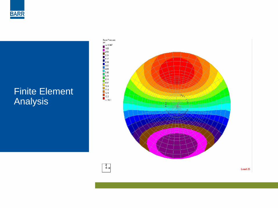
Finite Element Analysis

Barr Iowa Wind Foundation Projects
• Barton I and II• Carroll• Century I, II and III• Charles City• Crane Creek• Eclipse• Endeavor II• Flying Cloud• Hawkeye• Highland
• Ida Grove• Intrepid• Laurel• Lundgren• Macksberg• Morninglight• New Harvest• Pomeroy I, III and IV• Rippey• Rolling Hills
• Tjaden• Top of Iowa I and III• Valmont• Victory • Vienna I and II• Walnut• Wellsberg

Future Developments

Anchored precast beams (RUTE Foundation Systems)

Precast box spread(RUTE Foundation Systems)
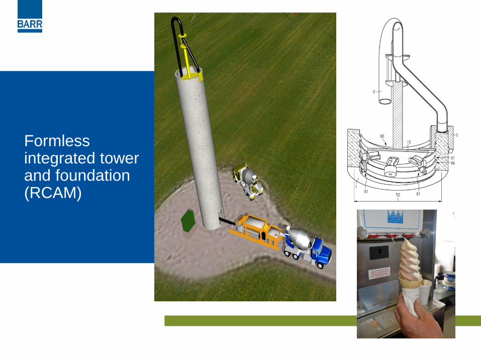
Formless integrated tower and foundation (RCAM)

Tower of precast column and panels (Hexcrete, ISU)

Questions?

unexpectedconditions –
cattle
• cattle on plastic / curing concrete• evaluate for restoration via composite
action with prepared overlay• hydro-demolition, preparation and overlay

Are wind turbines designed for tornados?
• Extreme winds in range of 50 m/s• Gust factoring / load factoring
equivalent speed in range of 100 m/s (230 mph) which is less than some tornados.
• Intense shears and reversals across rotor not considered (blade fail / tower strike)
Image: www.bluechannel24.com
