a practical guide to safely installing electrical wiring...
TRANSCRIPT
A Practical Guide to Safely Installing Electrical Wiring in Your Home
Ron Starr, Starr Electric
DIY Electrical Manual - Starr Electric
1
About the Author 2
About the Manual 2
Project Overview 3
Helpful Guides 3
Tools 4
Getting Started 6
Wiring 6
Conduit & Raceway 9
Boxes 10
Calculating Wires 12
Running Cables 14

DIY Electrical Manual - Starr Electric
2
About the Author Ron Starr has been the owner and chief electrician of Starr Electric since he founded the company in 1984. He has over 40 years of professional electrical experience and is dedicated to meeting customer needs for residential, commercial, and industrial sites. Ron has a passion for helping people succeed in DIY electrical installation. If at any point you find yourself in need of an expert electrician to tackle a task for you, Starr Electric is available to help. Visit www.StarrElectric.com or contact Ron Starr at 262-613-3255. The author would like to thank Stephanie Strang, Christine Bohl, and Zachary Ace Aiuppa for compiling this manual.
About the Manual As a Wisconsin homeowner installing electrical wiring, you need directions that are simple to understand and that follow state and national electrical code. This manual will walk you through electrical installation, step by step. A master list of supplies and tools will indicate exactly what you need, and important safety techniques will help you feel confident as you complete electrical work in your home. After obtaining an electrical permit from local authorities and following these directions, you'll be able to pass your inspection the first time and avoid paying substantial professional fees.
This manual is designed to help you: 1. Learn what tools are needed for installation 2. Determine what supplies and tools are needed based on your project 3. Create a plan for electrical wiring installation 4. Install electrical wiring according to state and national code 5. Gain access to expert tips that go beyond code regulations 6. Save money on future electrical repairs with DIY repair tips
DIY Electrical Manual - Starr Electric
3
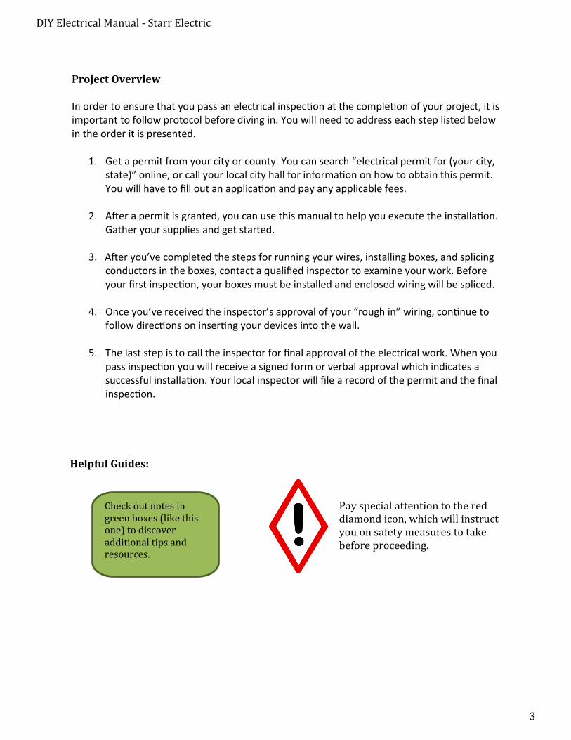
Project Overview
In order to ensure that you pass an electrical inspection at the completion of your project, it is important to follow protocol before diving in. You will need to address each step listed below in the order it is presented.
1. Get a permit from your city or county. You can search “electrical permit for (your city,state)” online, or call your local city hall for information on how to obtain this permit.You will have to fill out an application and pay any applicable fees.
2. After a permit is granted, you can use this manual to help you execute the installation.Gather your supplies and get started.
3. After you’ve completed the steps for running your wires, installing boxes, and splicingconductors in the boxes, contact a qualified inspector to examine your work. Beforeyour first inspection, your boxes must be installed and enclosed wiring will be spliced.
4. Once you’ve received the inspector’s approval of your “rough in” wiring, continue tofollow directions on inserting your devices into the wall.
5. The last step is to call the inspector for final approval of the electrical work. When youpass inspection you will receive a signed form or verbal approval which indicates asuccessful installation. Your local inspector will file a record of the permit and the finalinspection.
Pay special attention to the red diamond icon, which will instruct you on safety measures to take before proceeding.
Helpful Guides:
Check out notes in green boxes (like this one) to discover additional tips and resources.
DIY Electrical Manual - Starr Electric
4
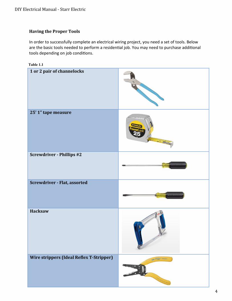
Having the Proper Tools
In order to successfully complete an electrical wiring project, you need a set of tools. Below are the basic tools needed to perform a residential job. You may need to purchase additional tools depending on job conditions.
1 or 2 pair of channelocks
25’ 1” tape measure
Screwdriver - Phillips #2
Screwdriver - Flat, assorted
Hacksaw
Wire strippers (Ideal Reflex T-Stripper)
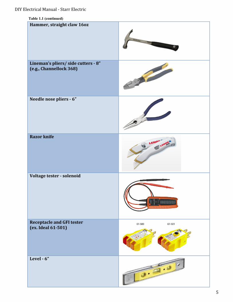
Table 1.1
DIY Electrical Manual - Starr Electric
5
Hammer, straight claw 16oz
Lineman’s pliers/ side cutters - 8” (e.g., Channellock 368)
Needle nose pliers - 6”
Razor knife
Voltage tester - solenoid
Receptacle and GFI tester (ex. Ideal 61-501)
Level - 6”
Table 1.1 (continued)
DIY Electrical Manual - Starr Electric
6
Getting Started
Before diving into the specifics of electrical installation, let’s discuss some supplies that will be needed for your project. In this section, you’ll learn how to identify and choose cables, conduits, and boxes before launching into your room plan layout. You will also learn where to properly drill holes in joists and studs for installing your cables. This is valuable information that will help you avoid redundant work.
Wiring
The wiring between the fuse box and the outlet or fixture will deliver electricity to operate the device you install. Choosing wiring of the proper gauge, amperage limit, and maximum wattage load limit will help you avoid misguided wiring that could trip circuit breakers or overload the circuits in your home. According to the National Electrical Code, you must choose wires and cables that are appropriate for your project in order to create an electrical system that is safe and well designed.
The GROUND or “G” on your sheathing indicates the presence of a ground wire.
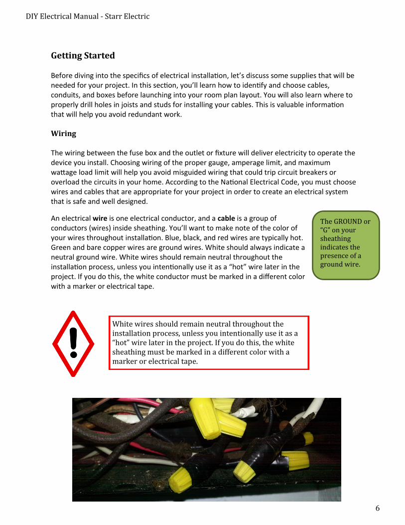
An electrical wire is one electrical conductor, and a cable is a group of conductors (wires) inside sheathing. You’ll want to make note of the color of your wires throughout installation. Blue, black, and red wires are typically hot. Green and bare copper wires are ground wires. White should always indicate a neutral ground wire. White wires should remain neutral throughout the installation process, unless you intentionally use it as a “hot” wire later in the project. If you do this, the white conductor must be marked in a different color with a marker or electrical tape.
White wires should remain neutral throughout the installation process, unless you intentionally use it as a “hot” wire later in the project. If you do this, the white sheathing must be marked in a different color with a marker or electrical tape.
DIY Electrical Manual - Starr Electric
7
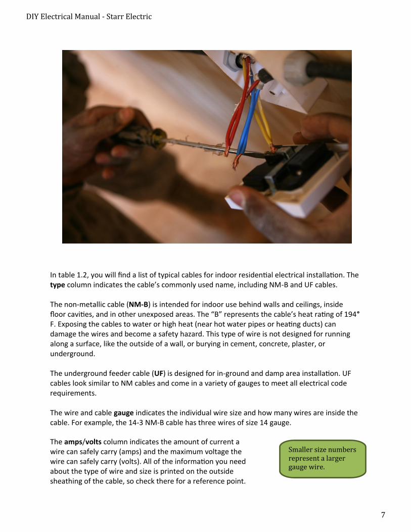
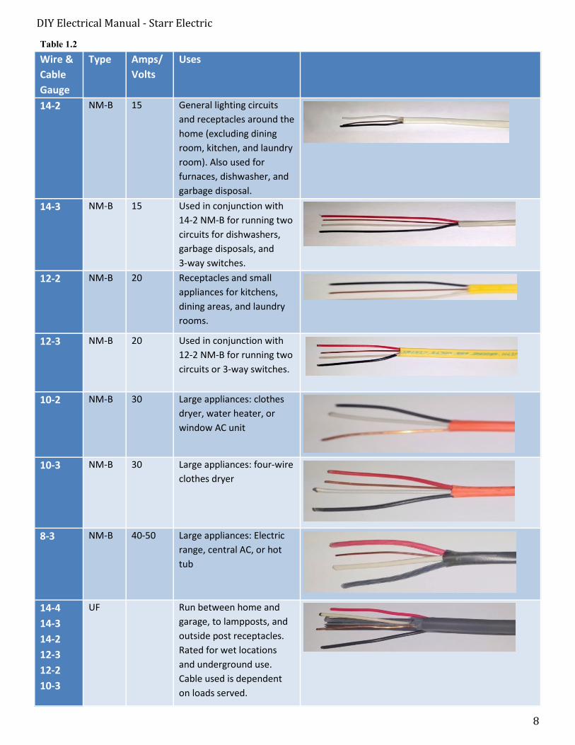
In table 1.2, you will find a list of typical cables for indoor residential electrical installation. The type column indicates the cable’s commonly used name, including NM-B and UF cables.
The non-metallic cable (NM-B) is intended for indoor use behind walls and ceilings, inside floor cavities, and in other unexposed areas. The “B” represents the cable’s heat rating of 194°F. Exposing the cables to water or high heat (near hot water pipes or heating ducts) can damage the wires and become a safety hazard. This type of wire is not designed for running along a surface, like the outside of a wall, or burying in cement, concrete, plaster, or underground.
The underground feeder cable (UF) is designed for in-ground and damp area installation. UF cables look similar to NM cables and come in a variety of gauges to meet all electrical code requirements.
The wire and cable gauge indicates the individual wire size and how many wires are inside the cable. For example, the 14-3 NM-B cable has three wires of size 14 gauge.
Smaller size numbers represent a larger gauge wire.
The amps/volts column indicates the amount of current a wire can safely carry (amps) and the maximum voltage the wire can safely carry (volts). All of the information you need about the type of wire and size is printed on the outside sheathing of the cable, so check there for a reference point.
DIY Electrical Manual - Starr Electric
8
Table 1.2
Wire &
Cable
Gauge
Type Amps/
Volts
Uses
14-2 NM-B 15 General lighting circuits
and receptacles around the
home (excluding dining
room, kitchen, and laundry
room). Also used for
furnaces, dishwasher, and
garbage disposal.
14-3 NM-B 15 Used in conjunction with
14-2 NM-B for running two
circuits for dishwashers,
garbage disposals, and
3-way switches.
12-2 NM-B 20 Receptacles and small
appliances for kitchens,
dining areas, and laundry
rooms.
12-3 NM-B 20 Used in conjunction with
12-2 NM-B for running two
circuits or 3-way switches.
10-2 NM-B 30 Large appliances: clothes
dryer, water heater, or
window AC unit
10-3 NM-B 30 Large appliances: four-wire
clothes dryer
8-3 NM-B 40-50 Large appliances: Electric
range, central AC, or hot
tub
14-4
14-3
14-2
12-3
12-2
10-3
UF Run between home and
garage, to lampposts, and
outside post receptacles.
Rated for wet locations
and underground use.
Cable used is dependent
on loads served.
DIY Electrical Manual - Starr Electric
9
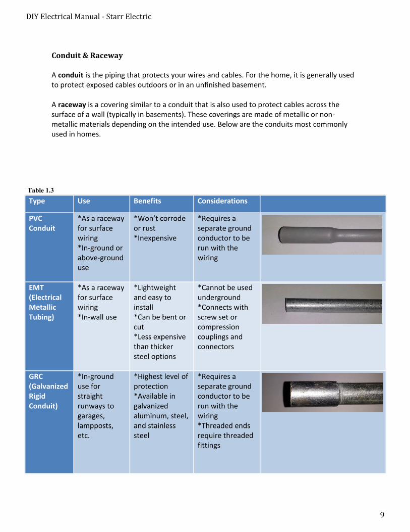
Conduit & Raceway
A conduit is the piping that protects your wires and cables. For the home, it is generally used to protect exposed cables outdoors or in an unfinished basement.
A raceway is a covering similar to a conduit that is also used to protect cables across the surface of a wall (typically in basements). These coverings are made of metallic or non-metallic materials depending on the intended use. Below are the conduits most commonly used in homes.
Type Use Benefits Considerations
PVC Conduit
*As a racewayfor surface wiring *In-ground orabove-ground use
*Won’t corrodeor rust *Inexpensive
*Requires aseparate ground conductor to be run with the wiring
EMT (Electrical Metallic Tubing)
*As a racewayfor surface wiring *In-wall use
*Lightweightand easy to install *Can be bent orcut *Less expensivethan thicker steel options
*Cannot be usedunderground *Connects withscrew set or compression couplings and connectors
GRC (Galvanized Rigid Conduit)
*In-grounduse for straight runways to garages, lampposts, etc.
*Highest level ofprotection *Available ingalvanized aluminum, steel, and stainless steel
*Requires aseparate ground conductor to be run with the wiring *Threaded endsrequire threaded fittings
Table 1.3
DIY Electrical Manual - Starr Electric
10
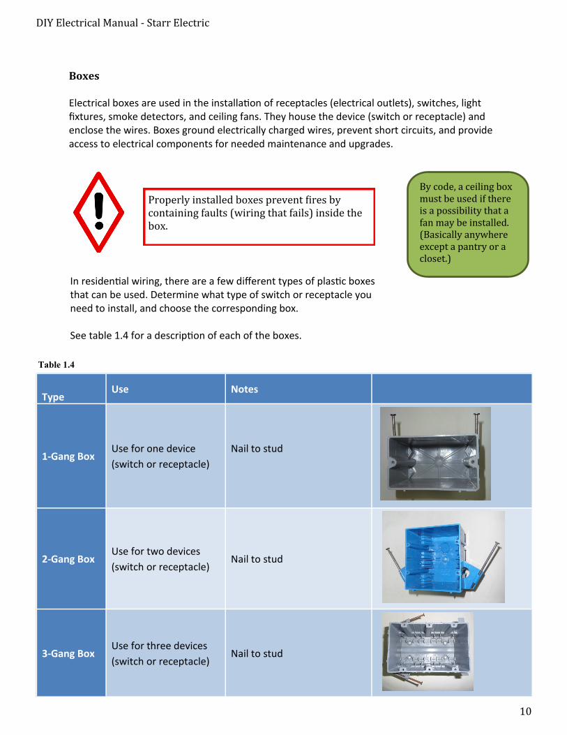
Boxes
Electrical boxes are used in the installation of receptacles (electrical outlets), switches, light fixtures, smoke detectors, and ceiling fans. They house the device (switch or receptacle) and enclose the wires. Boxes ground electrically charged wires, prevent short circuits, and provide access to electrical components for needed maintenance and upgrades.
By code, a ceiling box must be used if there is a possibility that a fan may be installed. (Basically anywhere except a pantry or a closet.)
Properly installed boxes prevent fires by containing faults (wiring that fails) inside the box.
In residential wiring, there are a few different types of plastic boxes that can be used. Determine what type of switch or receptacle you need to install, and choose the corresponding box.
See table 1.4 for a description of each of the boxes.
Table 1.4
Type Use Notes
1-Gang Box Use for one device
(switch or receptacle)
Nail to stud
2-Gang Box Use for two devices
(switch or receptacle) Nail to stud
3-Gang Box Use for three devices
(switch or receptacle) Nail to stud
DIY Electrical Manual - Starr Electric
11
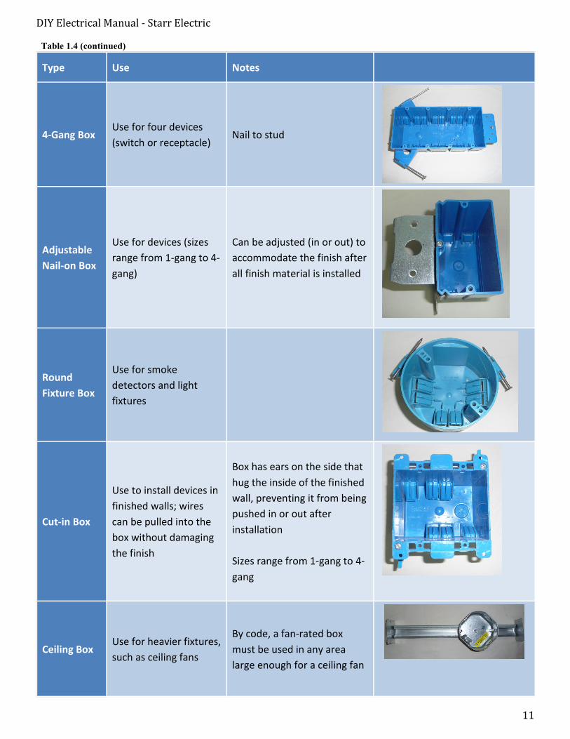
Table 1.4 (continued)
Type Use Notes
4-Gang Box Use for four devices
(switch or receptacle) Nail to stud
Adjustable
Nail-on Box
Use for devices (sizes
range from 1-gang to 4-
gang)
Can be adjusted (in or out) to
accommodate the finish after
all finish material is installed
Round
Fixture Box
Use for smoke
detectors and light
fixtures
Cut-in Box
Use to install devices in
finished walls; wires
can be pulled into the
box without damaging
the finish
Box has ears on the side that
hug the inside of the finished
wall, preventing it from being
pushed in or out after
installation
Sizes range from 1-gang to 4-
gang
Ceiling Box Use for heavier fixtures,
such as ceiling fans
By code, a fan-rated box
must be used in any area
large enough for a ceiling fan
DIY Electrical Manual - Starr Electric
12
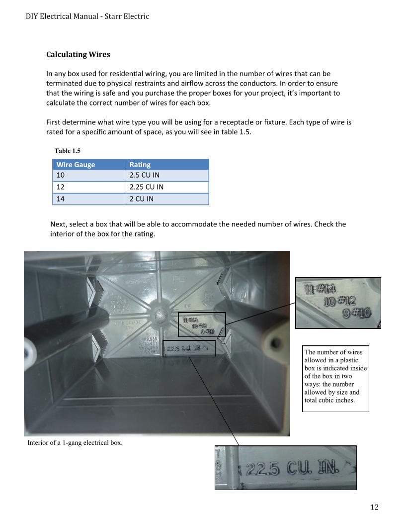
Calculating Wires
In any box used for residential wiring, you are limited in the number of wires that can be terminated due to physical restraints and airflow across the conductors. In order to ensure that the wiring is safe and you purchase the proper boxes for your project, it’s important to calculate the correct number of wires for each box.
First determine what wire type you will be using for a receptacle or fixture. Each type of wire is rated for a specific amount of space, as you will see in table 1.5.
Next, select a box that will be able to accommodate the needed number of wires. Check the interior of the box for the rating.
Wire Gauge Rating
10 2.5 CU IN
12 2.25 CU IN
14 2 CU IN
Table 1.5
Interior of a 1-gang electrical box.
The number of wires
allowed in a plastic
box is indicated inside
of the box in two
ways: the number
allowed by size and
total cubic inches.
DIY Electrical Manual - Starr Electric
13
After calculating the size of your box, a good practice would be to go up to the next size (or more) to leave ample room for the wires.
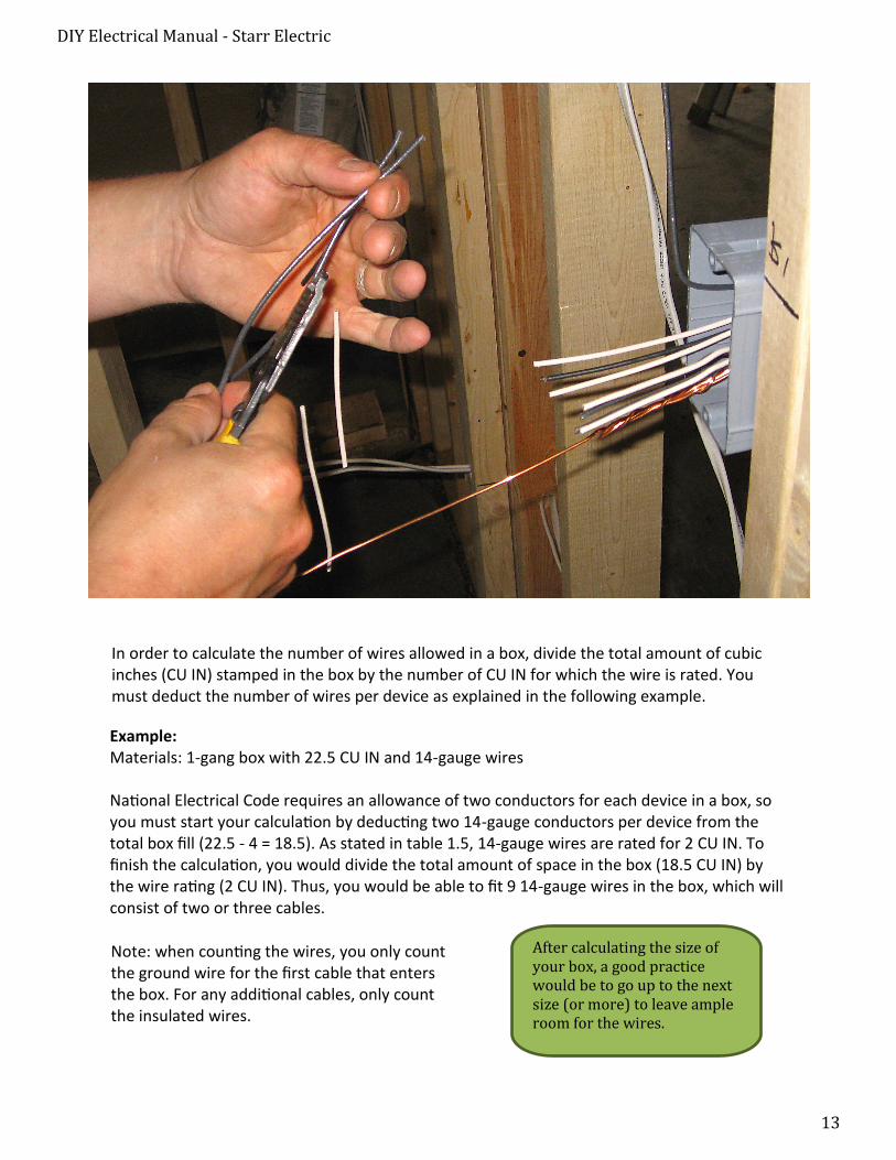
Example: Materials: 1-gang box with 22.5 CU IN and 14-gauge wires
National Electrical Code requires an allowance of two conductors for each device in a box, so you must start your calculation by deducting two 14-gauge conductors per device from the total box fill (22.5 - 4 = 18.5). As stated in table 1.5, 14-gauge wires are rated for 2 CU IN. To finish the calculation, you would divide the total amount of space in the box (18.5 CU IN) by the wire rating (2 CU IN). Thus, you would be able to fit 9 14-gauge wires in the box, which will consist of two or three cables.
In order to calculate the number of wires allowed in a box, divide the total amount of cubic inches (CU IN) stamped in the box by the number of CU IN for which the wire is rated. You must deduct the number of wires per device as explained in the following example.
Note: when counting the wires, you only count the ground wire for the first cable that enters the box. For any additional cables, only count the insulated wires.
DIY Electrical Manual - Starr Electric
14
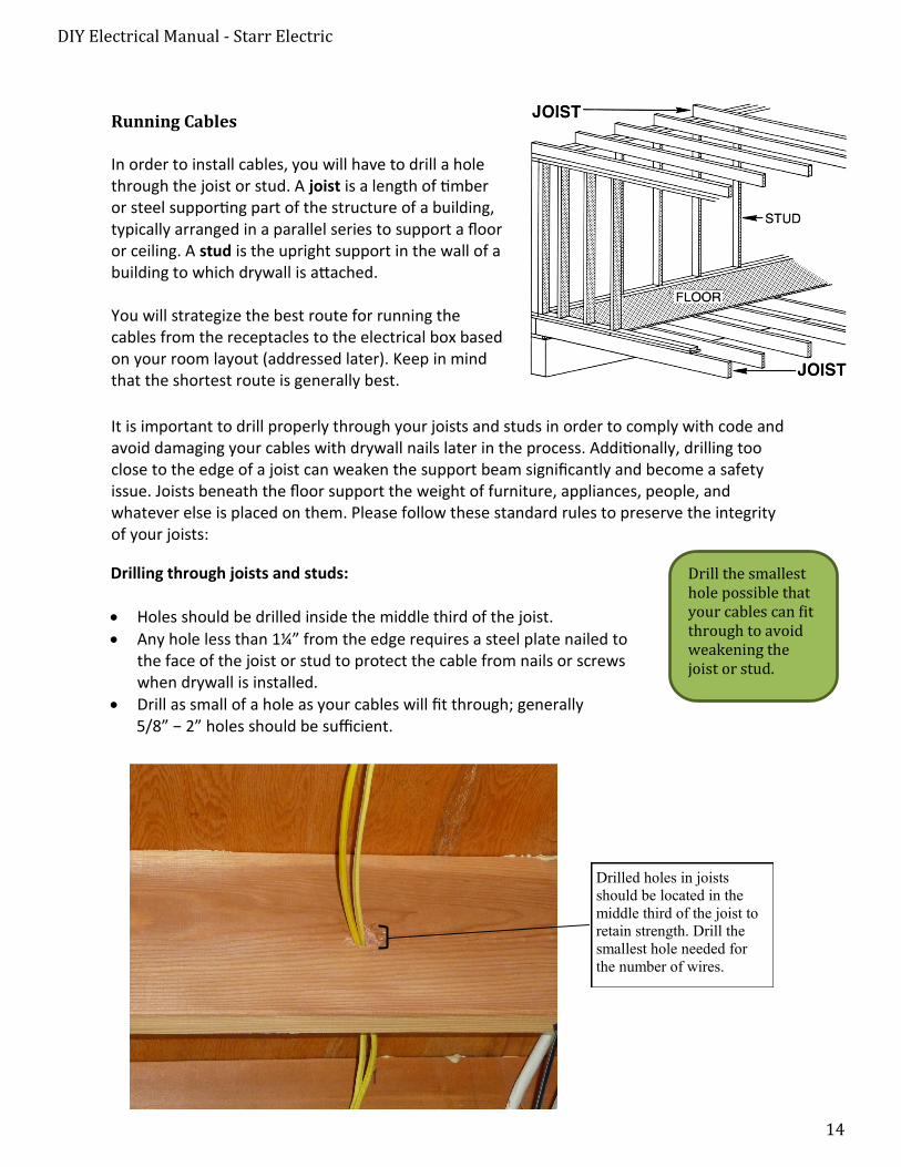
Running Cables
In order to install cables, you will have to drill a hole through the joist or stud. A joist is a length of timber or steel supporting part of the structure of a building, typically arranged in a parallel series to support a floor or ceiling. A stud is the upright support in the wall of a building to which drywall is attached.
You will strategize the best route for running the cables from the receptacles to the electrical box based on your room layout (addressed later). Keep in mind that the shortest route is generally best.
It is important to drill properly through your joists and studs in order to comply with code and avoid damaging your cables with drywall nails later in the process. Additionally, drilling too close to the edge of a joist can weaken the support beam significantly and become a safety issue. Joists beneath the floor support the weight of furniture, appliances, people, and whatever else is placed on them. Please follow these standard rules to preserve the integrity of your joists:
Drilling through joists and studs:
Holes should be drilled inside the middle third of the joist.
Any hole less than 1¼” from the edge requires a steel plate nailed tothe face of the joist or stud to protect the cable from nails or screwswhen drywall is installed.
Drill as small of a hole as your cables will fit through; generally5/8” − 2” holes should be sufficient.
Drill the smallest hole possible that your cables can fit through to avoid weakening the joist or stud.
Drilled holes in joists
should be located in the
middle third of the joist to
retain strength. Drill the
smallest hole needed for
the number of wires.
DIY Electrical Manual - Starr Electric
15
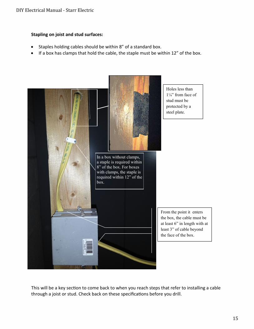
Holes less than
1¼” from face of
stud must be
protected by a
steel plate.
From the point it enters
the box, the cable must be
at least 6” in length with at
least 3” of cable beyond
the face of the box.
In a box without clamps,
a staple is required within
8” of the box. For boxes
with clamps, the staple is
required within 12” of the
box.
This will be a key section to come back to when you reach steps that refer to installing a cable through a joist or stud. Check back on these specifications before you drill.
Stapling on joist and stud surfaces:
Staples holding cables should be within 8” of a standard box.
If a box has clamps that hold the cable, the staple must be within 12” of the box.

DIY Electrical Manual - Starr Electric
16
The following four pages are templates the author may use to continue building on the manual.
= placeholder image

DIY Electrical Manual - Starr Electric
17
Terminations
Supplies:
Instructions: Step One
Instructions: Step Two
Instructions: Step Four
Instructions: Step Three
Description:
DIY Electrical Manual - Starr Electric
18
Connections
Supplies:
Instructions: Step One
Instructions: Step Two
Instructions: Step Four
Instructions: Step Three
Description:
DIY Electrical Manual - Starr Electric
19
Splicing
Supplies:
Instructions: Step One
Instructions: Step Two
Instructions: Step Four
Instructions: Step Three
Description:
DIY Electrical Manual - Starr Electric
20
Running and Installing a Cable
Supplies:
Instructions: Step One
Instructions: Step Two
Instructions: Step Four
Instructions: Step Three
Description: