a practical guide to dust suppression - j d ultrasonics€¦ · a practical guide to dust...
TRANSCRIPT
A Practical�Guide to�Dust�Suppression�
A Practical�Guide to�Dust�Suppression�
Compiled by David Blyth�J D UltraSonics Limited�
2�
Preface�
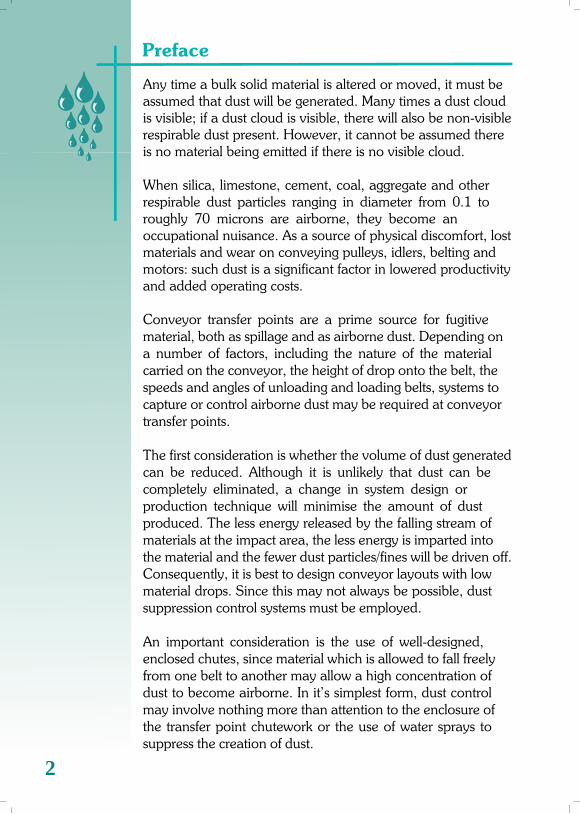
Any time a bulk solid material is altered or moved, it must be�assumed that dust will be generated. Many times a dust cloud�is visible; if a dust cloud is visible, there will also be non-visible�respirable dust present. However, it cannot be assumed there�is no material being emitted if there is no visible cloud.�
When silica, limestone, cement, coal, aggregate and other�respirable dust particles ranging in diameter from 0.1 to�roughly 70 microns are airborne, they become an�occupational nuisance. As a source of physical discomfort, lost�materials and wear on conveying pulleys, idlers, belting and�motors: such dust is a significant factor in lowered productivity�and added operating costs.�
Conveyor transfer points are a prime source for fugitive�material, both as spillage and as airborne dust. Depending on�a number of factors, including the nature of the material�carried on the conveyor, the height of drop onto the belt, the�speeds and angles of unloading and loading belts, systems to�capture or control airborne dust may be required at conveyor�transfer points.�
The first consideration is whether the volume of dust generated�can be reduced. Although it is unlikely that dust can be�completely eliminated, a change in system design or�production technique will minimise the amount of dust�produced. The less energy released by the falling stream of�materials at the impact area, the less energy is imparted into�the material and the fewer dust particles/fines will be driven off.�Consequently, it is best to design conveyor layouts with low�material drops. Since this may not always be possible, dust�suppression control systems must be employed.�
An important consideration is the use of well-designed,�enclosed chutes, since material which is allowed to fall freely�from one belt to another may allow a high concentration of�dust to become airborne. In it’s simplest form, dust control�may involve nothing more than attention to the enclosure of�the transfer point chutework or the use of water sprays to�suppress the creation of dust.�
3�
Table of Contents�
Introduction�
Water Suppression�
With Water, Less is More�
The Thermal Penalty for Added Water�
Ultrasonic Dry Fog Dust Suppression�
Mist Suppression Systems�
Placement and Position of Nozzles�
Pros & Cons of Fog and Mist Systems�
Adding Chemicals to Water�
Location, Location, Location�
Other Dust Suppression Equipment�
Conversion Tables�
...................................................................... 4�
........................................................... 5�
................................................ 7�
.......................... 8�
......................... 10�
............................................ 12�
............................. 13�
........................ 15�
.......................................... 16�
....................................... 17�
............................ 18�
.......................................................... 20�
4�
Introduction�
A Practical�Guide to�Dust�Suppression�
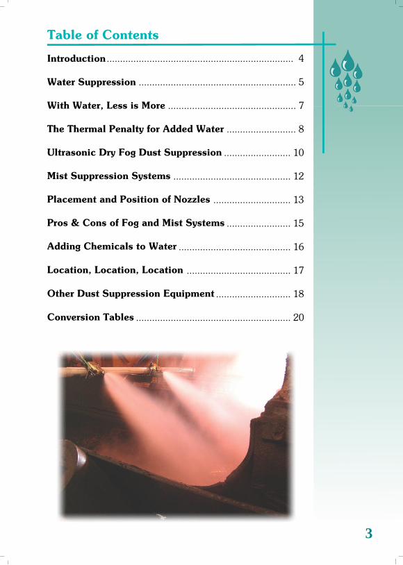
Dust Suppression is�the application of�water and/or�chemicals, either to�
the body of material to prevent fines from being carried off into�the air, or to the air above the material to return fugitive�airborne fines to the material bed.�
A significant advantage of dust suppression is that the material�does not have to be handled again. The suppressed dust�returns to the main body of conveyed material and the process�without requiring additional material handling equipment.�
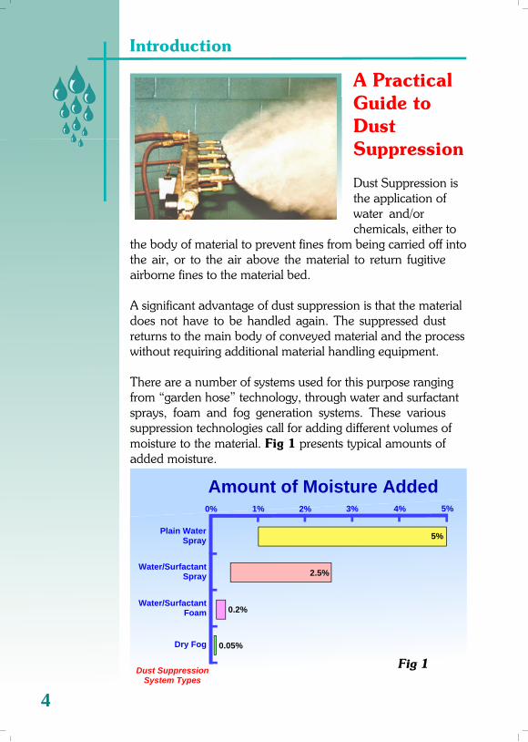
There are a number of systems used for this purpose ranging�from “garden hose” technology, through water and surfactant�sprays, foam and fog generation systems. These various�suppression technologies call for adding different volumes of�moisture to the material.�Fig 1� presents typical amounts of�added moisture.�
Plain Water�Spray�
0%�
Water/Surfactant�Spray�
Water/Surfactant�Foam�
Dry Fog�
1%� 2%� 3%� 4%� 5%�
5%�
2.5%�
0.2%�
0.05%�
Amount of Moisture Added�
Fig 1�Dust Suppression�System Types�
5�
Perhaps the oldest method for controlling fugitive dust is the�application of water over the body of material. By wetting the�fines, either as they lay in the material body or as they are�being picked up into the air, the weight of each dust particle is�increased so they are less likely to become airborne. The�moisture also increases the cohesive force of the material body�itself, creating larger, heavier groups of particles and making it�more difficult for air movement to carry away the dust�particles. This can be done by applying the water through a�series of properly sized spray nozzles at a point where the�material expands and takes in air, such as during discharge�from the head drum in a transfer chute.�
Water can also be applied to create a “curtain” around a�transfer point, so any dust fines that become airborne come�into contact with the water sprays surrounding the open area�around the chute. The water droplets are expected to make�contact with the dust fines, increasing their mass to remove�them from the air stream.�
The most effective sprays come from low-velocity systems.�High-velocity sprays can add energy to the air and the dust�particles. This energy is counterproductive to the task of�keeping (or returning) the dust with the material body. High�velocity air movement can keep dust particles in suspension.�
Water-based suppression systems can become more�sophisticated as the engineering moves beyond “garden hose”�technology in efforts to improve results. The effectiveness of�water spray systems is dependent on the velocity of applied�water, the size of the nozzle’s orifice and the location of the�spray nozzles. The techniques to improve plain water-spray�dust suppression include a reduction of droplet size, an�increase in droplet frequency, an increase of the droplet’s�velocity, or a decrease in the droplet’s surface tension, making�it easier to merge with dust particles.�
The application of dust suppression water and/or chemicals at�transfer points must be controlled automatically so that water is�applied only when the conveyors are running and there is a�
Water Suppression�

6�
material present. This can be accomplished with conveyor�system interlocks and other sensors, including microwave (or�
similar) sensors that read both material�on the belt and loaded belt�
movement.�
Fig 2� shows a spray�control valve capable of�controlling the flow of�
any fluid by mechanically�sensing belt movement without the need for an independent�power supply. The valve�can be positioned so that�the wheel contacts the�belt when it is loaded,�therefore operating only�when material is being�conveyed.�Fig 3�.�
Plain water spray�application systems are�relatively simple to design and operate, and water has only a�minimal residual effect. Water is generally inexpensive, it is�usually easy to obtain; it is safe for the environment and for�workers who come into contact with it.�
Dust suppression systems utilising water are relatively simple�systems that do not require the use of a costly elaborate�enclosure or hoods. They are typically cheaper to install and�
use far less space than�the dry collection�systems. Changes can�be made after startup�with minimum expense�and downtime.�Unfortunately the�application of water�has several liabilities to�be considered.�
Fig 2�
Fig 3�
Dust Suppression over open rail track hoppers�
7�
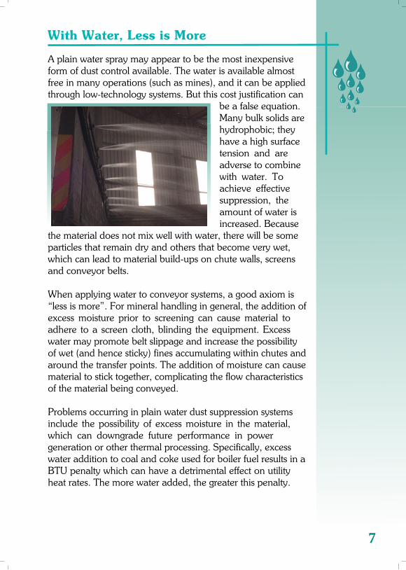
A plain water spray may appear to be the most inexpensive�form of dust control available. The water is available almost�free in many operations (such as mines), and it can be applied�through low-technology systems. But this cost justification can�
be a false equation.�Many bulk solids are�hydrophobic; they�have a high surface�tension and are�adverse to combine�with water. To�achieve effective�suppression, the�amount of water is�increased. Because�
the material does not mix well with water, there will be some�particles that remain dry and others that become very wet,�which can lead to material build-ups on chute walls, screens�and conveyor belts.�
When applying water to conveyor systems, a good axiom is�“less is more”. For mineral handling in general, the addition of�excess moisture prior to screening can cause material to�adhere to a screen cloth, blinding the equipment. Excess�water may promote belt slippage and increase the possibility�of wet (and hence sticky) fines accumulating within chutes and�around the transfer points. The addition of moisture can cause�material to stick together, complicating the flow characteristics�of the material being conveyed.�
Problems occurring in plain water dust suppression systems�include the possibility of excess moisture in the material,�which can downgrade future performance in power�generation or other thermal processing. Specifically, excess�water addition to coal and coke used for boiler fuel results in a�BTU penalty which can have a detrimental effect on utility�heat rates. The more water added, the greater this penalty.�
With Water, Less is More�

8�
The Thermal Penalty for Added Moisture�
There is a substantial performance penalty added to�combustion and other thermal processes when the water�content of the fuel is increased. In applications like coal-fired�power plants and cement plants, water added to the material�going into the thermal process must be “burned off” by the�process. This can dramatically reduce the process efficiency�and increase fuel costs.�
It requires 3,064 kilojoules per litre (1,320 BTU per pound) to�raise water from 21°C (70°F) to it’s vaporization temperature�of 149°C (300°F). It only takes 9.1 kg or 9.1 litres (20 pounds)�of water to increase the moisture content of one tonne of�material by one percent. As a gallon of water weighs�approximately 4.5 kg (10 pounds), the addition of less than�2.0 gallons (9.1 litres) of water to a tonnne of material will�raise the moisture content of a tonnne of material by 1�percent. Vaporizing this modest amount of water produces a�heat loss of 27,850 kilojoules (26,400 BTU).�
The thermal penalty typically created by the various dust�suppression methods is displayed in�Fig 4�.�
Because a “plain” water spray requires the highest volume of�moisture for effective dust suppression, this method extracts�the highest thermal penalty. While the use of a simple water�
Plain Water�Spray�
0%�
Water/Surfactant�Spray�
Water/Surfactant�Foam�
Dry Fog�
1%� 2%� 3%� 4%� 5%�
27,852 - 139,260 kilojoules�26,000 - 132,000 BTU�
Amount of Moisture Added�Percent of Material Weight�
Fig 4�Dust Suppression�System Types�
8,356 - 69,630 kilojoules�7,920 - 66,000 BTU�
1,393 - 5,570 kilojoules�1,320 - 5,280 BTU�
279 - 1,393 kilojoules�264 - 1,320 BTU�
Thermal Penalty per�Tonne of Material�
spray for dust suppression may be a lower cost because the�water is readily available and there is less “out-of-pocket”�expense, the penalty for the addition of surplus moisture can�be very costly indeed.�
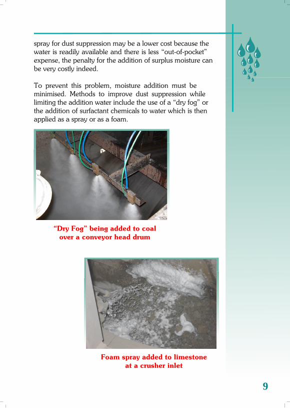
To prevent this problem, moisture addition must be�minimised. Methods to improve dust suppression while�limiting the addition water include the use of a “dry fog” or�the addition of surfactant chemicals to water which is then�applied as a spray or as a foam.�
9�
“Dry Fog” being added to coal�over a conveyor head drum�
Foam spray added to limestone�at a crusher inlet�
10�
Ultrasonic Dry Fog Suppression Systems�
“UltraFine Fog” fugitive dust suppression works like a�combination of a wet scrubber and a fabric filter. The�generated ultra-fine fogging blanket acts like a fabric filter in�that a dust particle cannot pass through it without colliding�with a droplet. Since the droplet consists of water, the dust�particle does become somewhat wet as in a true flooded�scrubber. This phenomenon can be called agglomeration and�solving fugitive dust emission problems with ultra-fine water�droplet atomisation begins with the theory of agglomeration.�Agglomeration can be defined as the gathering of mass into a�larger mass, or cluster.�
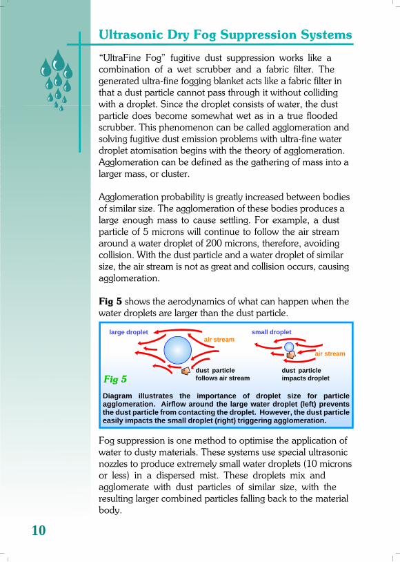
Agglomeration probability is greatly increased between bodies�of similar size. The agglomeration of these bodies produces a�large enough mass to cause settling. For example, a dust�particle of 5 microns will continue to follow the air stream�around a water droplet of 200 microns, therefore, avoiding�collision. With the dust particle and a water droplet of similar�size, the air stream is not as great and collision occurs, causing�agglomeration.�
Fig 5� shows the aerodynamics of what can happen when the�water droplets are larger than the dust particle.�
Fog suppression is one method to optimise the application of�water to dusty materials. These systems use special ultrasonic�nozzles to produce extremely small water droplets (10 microns�or less) in a dispersed mist. These droplets mix and�agglomerate with dust particles of similar size, with the�resulting larger combined particles falling back to the material�body.�
small droplet�air stream�
dust particle�follows air stream�
dust particle�impacts droplet�
Diagram illustrates the importance of droplet size for particle�agglomeration. Airflow around the large water droplet (left) prevents�the dust particle from contacting the droplet. However, the dust particle�easily impacts the small droplet (right) triggering agglomeration.�
large droplet�
air stream�
Fig 5�
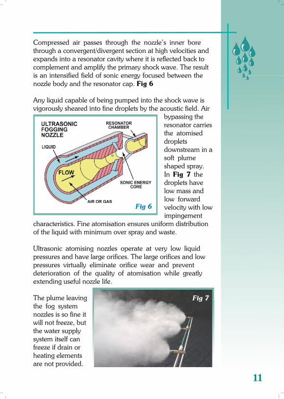
Compressed air passes through the nozzle’s inner bore�through a convergent/divergent section at high velocities and�expands into a resonator cavity where it is reflected back to�complement and amplify the primary shock wave. The result�is an intensified field of sonic energy focused between the�nozzle body and the resonator cap.�Fig 6�
Any liquid capable of being pumped into the shock wave is�vigorously sheared into fine droplets by the acoustic field. Air�
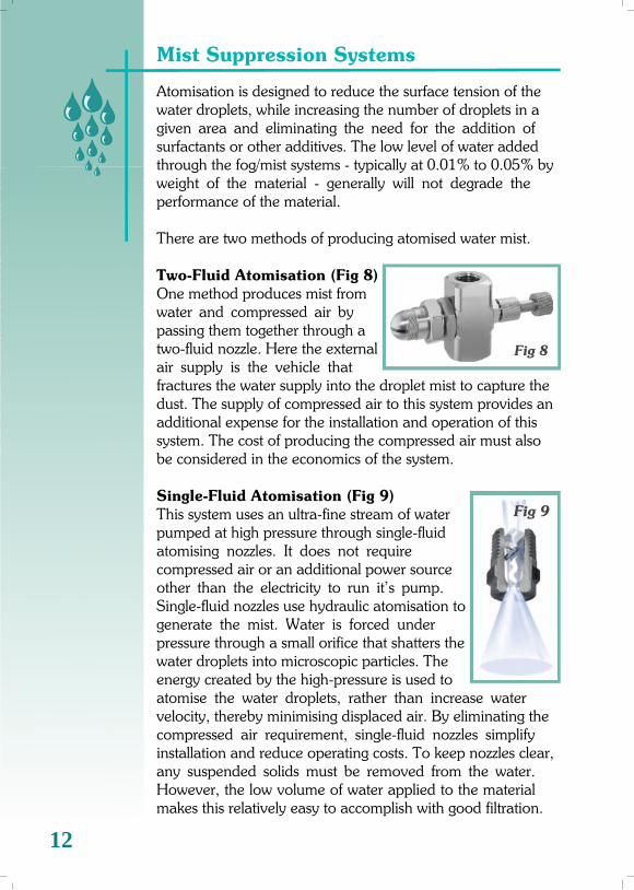
bypassing the�resonator carries�the atomised�droplets�downstream in a�soft plume�shaped spray.�In�Fig 7� the�droplets have�low mass and�low forward�velocity with low�impingement�
characteristics. Fine atomisation ensures uniform distribution�of the liquid with minimum over spray and waste.�
Ultrasonic atomising nozzles operate at very low liquid�pressures and have large orifices. The large orifices and low�pressures virtually eliminate orifice wear and prevent�deterioration of the quality of atomisation while greatly�extending useful nozzle life.�
The plume leaving�the fog system�nozzles is so fine it�will not freeze, but�the water supply�system itself can�freeze if drain or�heating elements�are not provided.�
11�
Fig 6�
Fig 7�
Atomisation is designed to reduce the surface tension of the�water droplets, while increasing the number of droplets in a�given area and eliminating the need for the addition of�surfactants or other additives. The low level of water added�through the fog/mist systems - typically at 0.01% to 0.05% by�weight of the material - generally will not degrade the�performance of the material.�
There are two methods of producing atomised water mist.�
Two-Fluid Atomisation (Fig 8)�One method produces mist from�water and compressed air by�passing them together through a�two-fluid nozzle. Here the external�air supply is the vehicle that�fractures the water supply into the droplet mist to capture the�dust. The supply of compressed air to this system provides an�additional expense for the installation and operation of this�system. The cost of producing the compressed air must also�be considered in the economics of the system.�
Single-Fluid Atomisation (Fig 9)�This system uses an ultra-fine stream of water�pumped at high pressure through single-fluid�atomising nozzles. It does not require�compressed air or an additional power source�other than the electricity to run it’s pump.�Single-fluid nozzles use hydraulic atomisation to�generate the mist. Water is forced under�pressure through a small orifice that shatters the�water droplets into microscopic particles. The�energy created by the high-pressure is used to�atomise the water droplets, rather than increase water�velocity, thereby minimising displaced air. By eliminating the�compressed air requirement, single-fluid nozzles simplify�installation and reduce operating costs. To keep nozzles clear,�any suspended solids must be removed from the water.�However, the low volume of water applied to the material�makes this relatively easy to accomplish with good filtration.�
12�
Mist Suppression Systems�
Fig 9�
Fig 8�
The placement of the fogging nozzles is the most important�aspect to producing effective results with no wetting of�material. The fog should be generated and contained in a�properly designed shrouding. This eliminates dissipation due�to wind and also produces the treatment time necessary to�suppress the dust. The fog is generated above the dust�problem area, not on the material. As the airborne dust enters�the confine, UltraFine Fog agglomeration occurs and the dust�is suppressed in situ.�
A simple system schematic is shown in�Fig 10�. In this picture�two spray bars are mounted on the covers. They are heat�traced and insulated assemblies. The enclosure has a quick�release cover, which makes it easy to service the nozzles as�required. This picture also shows the regulator control�cabinets, which are used to regulate the air and water�pressures and would also include solenoid valves linked into�the conveyor drives, along with the flex hoses used to connect�the two fluids.�
13�
Placement and Position of Nozzles�
INSULATED AND HEATED�100 X 100mm SPRAY BAR ENCLOSURE�
LENGTH AS REQUIRED�
CONVEYOR�
HOOD (BY CUSTOMER)�
INSULATED AND HEATED�100 X 100mm SPRAY BAR�
ENCLOSURE�LENGTH AS REQUIRED�
ANGLED 45° HOOD�
FLEXIBLE�CONNECTING�
HOSES�
SPRAY BAR�PRESSURE REGULATOR�
CONTROL CABINET�
COMPRESSED AIR�AND WATER SUPPLY�
Fig 10�
Typical conveyor transfer point and crusher shrouding along�with location of the nozzles are shown in�Fig 11�and�Fig 12�respectively.�
A general rule of thumb is that the height of the conveyor�cover be approximately 1 metre above the product level on the�belt and the cover length 3 times the belt speed (m/s). The�basic principles involved for location of the nozzles are as�follows:-�
• Nozzle spray pattern must not directly impinge upon any�surface.�
• Nozzles should be mounted in order to maximise the�ability to fill the shrouding.�
• The fog should avoid direct contact with the material�being suppressed.�
• Nozzles must be protected or shielded to avoid damage�from falling material.�
• Nozzles should be mounted to minimise exposure to a�heavy-laden dust air stream. This will void erosion of the�nozzle components.�
• Spray pattern of nozzles should be generated so that all�the fugitive dust emissions are forced to pass through�the blanket of fog.�
14�
Fig 11�
Fig 12�
Typical Transfer Point�Treated by Fog Nozzles�
Typical Crusher�Transfer Point�
Treated by�Fog Nozzles�
Fog systems provide highly effective dust capture combined�with economical capital and operating costs.�
A well designed fogging system can provide excellent control�of dust at the point of application without the need for�chemical additives. This is especially important for processes�such as wood chip transport destined for fine paper making.�Many mills are very concerned over the application of any�chemical that might negatively affect the pulp or degrade the�quality of the finished paper.�
Since fog systems only add water, they protect the integrity of�the customer process. Total moisture addition to the bulk�material can be realistically less than 0.1%. This makes fog�suppression systems attractive in industries that cannot tolerate�excess moisture, such as cement and lime production.�
Mains water is typically required for fog suppression systems,�so filtration to remove suspended solids from the water supply�is required. As high pressure misting nozzles have a very small�orifice to produce droplets, the water used for this operation�must be treated to be free of particulate and suspended solids.�Nozzles can clog if the water treatment system is not serviced at�required intervals.�
Another consideration prior to choosing a fogging device is the�air volume and velocity at the open area surrounding the�transfer point or chute. For truly effective performance, fog�dust suppression systems require tight enclosure of the transfer�point that minimises turbulent, high-velocity air movement�through the system. Since the fog droplets are very small, both�the fog droplets and the dust can be carried out of the�treatment area onto surrounding equipment by high-velocity�air exiting the chute.�
This type of system works well where the area to be treated is�not large. A potential drawback of a fogging application is that�treatment is site specific. That is, dust control is achieved only�at the point of application. Several fogging devices may be�required for a conveyor system with multiple transfer points.�
15�
Pros & Cons of Fog and Mist Systems�
To improve the wetting characteristics of water and also reduce�overall water usage and minimise the drawbacks associated�with excessive moisture addition, it is a common practice to�“enhance” the water by adding chemical surfactants. The�purpose of the surfactant addition is to improve the dust�suppressant performance of the water.�
If dust from coal, petroleum coke or other similar materials falls�onto a pool of water on the ground, the dust particles can lay�on top of the water. If undisturbed, this dust can remain on the�surface of the pool for hours. This phenomenon takes place�because these materials are hydrophobic; they do not mix well�with water. It is not possible or practical to alter the nature of�the dust particles to give them greater affinity for water.�Therefore chemicals are added to alter the water molecules, so�they attract or at least join with the dust fines which they�contact.�
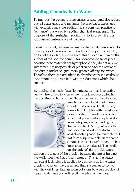
By adding chemicals (usually surfactants - surface acting�agents) the surface tension of the water is reduced, allowing�the dust fines to become wet.�To understand surface tension,�
imagine a drop of water lying on a�smooth, flat surface. It will usually�form a liquid bubble with well-defined�sides. It is the surface tension of the�water that prevents the droplet walls�from collapsing and spreading as a�thin water sheet. A drop of water that�has been mixed with a surfactant such�as dishwashing soap, for example, will�not form a liquid bubble on the same�surface because its surface tension has�been drastically reduced. The “walls”�on the side of the droplet cannot�
support the weight of the droplet, because the forces holding�the walls together have been altered. This is the reason�surfactant technology is applied to dust control. If the water�droplets no longer have a surface that is a barrier to contact�with the dust fines, then random collisions between droplets of�treated water and dust will result in wetting of the fines.�
16�
Adding Chemicals to Water�

Fig 13�
sonic
om
�
FOG SYSTEM NOZZLES�
sonic
om
�
sonic
om
�
17�
Location, Location, Location�
In fog, foam, water and water/chemical spray applications, the�sites chosen for nozzle placement and suppressant delivery�patterns are as important as the selection of material to be�applied. Even the best designed program will fail if the�suppressant material is not delivered to the correct location to�allow intimate mixing with the dust fines.�
The success of the suppression effort relies on the proper�mixing together of the material and the suppressant at the�transfer point. When applying dust control, whether the�suppressant is simply water or a surfactant/water mix as a�spray or foam, it is best to locate the suppression system as�close to the beginning of the transfer point as possible. That�way, the forces of the moving material fold the suppressant�into the material body as it moves through the transfer point.�
The installation of fog systems is a little different in that fog�systems are designed to treat the air above the material, rather�than the material body itself. Therefore, the application point�for the fog mist is generally near the end of the transfer point�Fig 13�. This allows the material load to settle and any pickups�for active or passive dust collection systems to remove dust-�laden air without the risk of binding the filtration media with�moistened dust particles. Fog generation nozzles are installed�to cover the full width of the conveyor’s skirted area. It is�recommended that skirtboard height be at least 800mm to�allow the plume of the nozzle output to reach optimum�coverage.�

Sprinklers:� Used mainly where wetting is required over a�wide area such as roadways and open yards. They are limited�
by the throw achievable from�each head and rely on good�water pressure and flow. Sizes�are selected according to the�application and the units can be�set to spray full or part circle�patterns. This ensures maximum�areas are covered with the�
minimum of over lap between spray heads. Water�consumption varies typically between 0.3 and 95 m³/hr.�
Rain Guns:� Dust suppression rain guns have been specifically�designed to provide immediate�and efficient dampening/wetting�over large areas with minimal�water consumption.�
A high frequency drive�mechanism provides a fine water�curtain and gives excellent water�distribution with minimum�maintenance. Units can be self adjusting and range from 12 to�150 m³/hr with spray trajectories up to 120 metres.�
Sprinklers and rain�guns can be used�together to achieve�an overall�suppression effect�over areas of concern�and provide the best�possible results with�budget costs and�water conservation in�mind.�
18�
Other Dust Suppression Equipment�

19�
Water Spray Nozzle Systems:� Such systems provide�immediate dampening of general material handling processes�and site boundaries. The nozzle design ensures a cone spray�pattern is achieved at pressures from 1 to 8 Bar.�
These types of nozzle systems are a low cost option for material�handling processes/site boundaries where wetting is not a�problem. Nozzles are available in various materials including�plastic, stainless steel and brass with flow volumes ranging�from 0.3 lts/min up to 90 lts/min per nozzle.�
Fog Cannon:�When vast open�spaces require�dust suppression�and a semi�permanent�system is not a�practical option,�the solution may�lie with the�introduction of a fog cannon to the site.�
These huge mobile and expensive units can utilise up to 60�hydraulic spray nozzles mounted circumferentially around the�outlet head of a large fan assisted barrel. The concentration of�nozzle spray together with the high flow of air from the fan,�throws the droplets many metres towards the source of the�dust activity. The droplets scatter in a plume of relatively soft�spray and can capture fugitive dust before it becomes airborne�and a major problem.�

Multiply� by� to obtain� Multiply� by� to obtain�Area� Pressure�cm²� 0.0010764� ft²� bar� 14.50377� lbf/inch²�cm²� 0.1550003� inch²� bar� 1.02� Kgf/cm²�ft²� 0.09290304� m²� bar� 100,000.0� N/m² (Pa)�ft²� 929.0304� cm²� bar� 750.1� mm Hg�ft²� 92903.04� mm²� bar� 29.53� inch Hg�
inch²� 0.0006452� m²� bar� 0.9871668� atm�inch²� 6.4516� cm²� lbf/inch²� 0.06894757� bar�inch²� 645.16� mm²� lbf/inch²� 0.07030697� Kgf/cm²�m²� 1.19599� yard²� lbf/inch²� 6894.757� N/m² (Pa)�m²� 10.7639� ft²� lbf/inch²� 51.71� mm Hg�m²� 1550.003� inch²� lbf/inch²� 2.036� inch Hg�
mm²� 0.00001076391� ft²� lbf/inch²� 0.0680461� atm�mm²� 0.00155� inch²�yard²� 0.8361274� m²� Volume�
cm³� 0.0610234� inch³�Flow� ft³� 0.02831685� m³�ft³/min� 1.699� m³/hr� ft³� 28.31685� litre�ft³/min� 0.0283� m³/min� Imp gal� 0.004546092� m³�ft³/min� 0.000472� m³/sec� Imp gal� 4.546092� litre�ft³/min� 1699� lt/hr� Imp gal� 1.20032� US gal�ft³/min� 28.317� lt/min� Imp gal� 0.16054� ft³�ft³/min� 0.4719� lt/sec� inch³� 16387.06� mm³�ft³/min� 0.4719� dm³/sec� inch³� 16.38706� cm³�lt/min� 0.22� Imp gal/min� inch³� 0.000016387� m³�lt/min� 0.264172� US gal/min� litre� 0.001� m³�lt/min� 0.035315� ft³/min� litre� 0.2199692� Imp gal�lt/min� 0.000589� ft³/sec� litre� 0.03531466� ft³�lt/sec� 0.22� Imp gal/sec� litre� 61.0234� inch³�lt/sec� 0.264172� US gal/sec� m³� 219.9692� Imp gal�lt/sec� 2.11888� ft³/min� m³� 35.31466� ft³�lt/sec� 0.035315� ft³/sec� m³� 1000.0� litre�lt/sec� 0.06� m³/min� m³� 61023.4� inch³�lt/sec� 0.001� m³/sec� mm³� 0.000061024� inch³�
m³/sec� 2118.88� ft³/min�m³/sec� 35.31� ft³/sec� 1 micron� equals� 0.00004 inch�m³/sec� 13198.15� Imp gal/min� 1 micron� equals� 0.001mm�
CONVERSION TABLES�