a practical guide for systemverilog assertions · your patience during the long hours spent in...
TRANSCRIPT

A Practical Guide for SystemVerilog Assertions
A Practical Guide for System Veri log Assertions
by
Srikanth Vijayaraghavan
Meyyappan Ramanathan
Springe]
Srikanth Vijayaraghavan & Meyyappan Ramanthan Synopsys, Inc. Mountan View, CA USA
A Practical Guide for SystemVerilog Assertions
Library of Congress Control Number: 2005049012
ISBN 0-387-26049-8 e-lSBN 0-387-26173-7
ISBN 9780387260495
Printed on acid-free paper.
© 2005 Springer Science-i-Business Media, Inc. All rights reserved. This work may not be translated or copied in whole or in part without the written permission of the publisher (Springer Science-i-Business Media, Inc., 233 Spring Street, New York, NY 10013, USA), except for brief excerpts in connection with reviews or scholarly analysis. Use in connection with any form of information storage and retrieval, electronic adaptation, computer software, or by similar or dissimilar methodology now know or hereafter developed is forbidden. The use in this publication of trade names, trademarks, service marks and similar terms, even if the are not identified as such, is not to be taken as an expression of opinion as to whether or not they are subject to proprietary rights.
Printed in the United States of America.
9 8 7 6 5 4 3 2
springer.com

Dedication
To my wonderful wife, Anupama - I could not have done this without your love and support.
Srikanth Vijayaraghavan Synopsys, California
To my wife, Devi, and my children, Parvathi and Aravind - thank you for your patience during the long hours spent in completing the book.
Meyyappan Ramanathan Synopsys, California
Table of Contents
LIST OF FIGURES XIII
LIST OF TABLES XIX
FOREWORD XXI
PREFACE XXIII
CHAPTER 0: ASSERTION BASED VERIFICATION 1
CHAPTER 1: INTRODUCTION TO SVA 7
1.1 What is an Assertion? 7 1.2 Why use SystemVerilog Assertions (SVA)? 8 1.3 SystemVerilog Scheduling 10 1.4 SVA Terminology 11
1.4.1 Concurrent assertions 11 1.4.2 Immediate assertions 12
1.5 Building blocks of SVA 13 1.6 A simple sequence 14 1.7 Sequence with edge definitions 16 1.8 Sequence with logical relationship 17 1.9 Sequence Expressions 18 1.10 Sequences with timing relationship 19 1.11 Clock definitions in SVA 21 1.12 Forbidding a property 22 1.13 A simple acfion block 24 1.14 Implication operator 24
1.14.1 Overlapped implication 25 1.14.2 Non-overlapped implication 26 1.14.3 Implication with a fixed delay on the consequent 27 1.14.4 Implication with a sequence as an antecedent 29
1.15 Timing windows in SVA Checkers 30 1.15.1 Overlapping timing window 33 1.15.2 Indefinite timing window 33
1.16 The "ended" construct 35

viii A PRACTICAL GUIDE FOR systemverilog assertions
1.17 SVA Checker using parameters 39 1.18 SVA Checker using a select operator 40 1.19 SVA Checker using "true expression 41 1.20 The "Spast" construct 43
1.20.1 The Spast construct with clock gating 45 1.21 Repetition operators 45
1.21.1 Consecutive repetition operator [*] 47 1.21.2 Consecutive repetition operator [*] on a sequence 48 1.21.3 Consecutive repetition operator [*] on a sequence with a delay
window 50 1.21.4 Consecutive repetition operator [*] and eventuality operator 51 1.21.5 Go to repetition operator [->] 53 1.21.6 Non-consecutive repetition operator [=] 54
1.22 The "and" construct 56 1.23 The "intersect" construct 58 1.24 The "or" construct 61 1.25 The "firstmatch" construct 63 1.26 The "throughout" construct 64 1.27 The "within" construct 66 1.28 Built-in system functions 67 1.29 The "disable iff' construct 69 1.30 Using "intersect" to control length of the sequence 70 1.31 Using formal arguments in a property 72 1.32 Nested implication 74 1.33 Using if/else with implication 76 1.34 Multiple clock definitions in SVA 77 1.35 The "matched" construct 79 1.36 The "expect" construct 80 1.37 SVA using local variables 81 1.38 SVA calling subroutine on a sequence match 84 1.39 Connecting SVA to the design 86 1.40 SVA for functional coverage 88
CHAPTER 2: SVA SIMULATION METHODOLOGY 89
2.1 A sample system under verification 89 2.1.1 The Master device 89 2.1.2 The Mediator 92 2.1.3 The Target device 94
2.2 Block level verification 96 2.2.1 SVA in design blocks 96 2.2.2 Arbiter verification 97

A PRACTICAL GUIDE FOR systemverilog assertions ix
2.2.3 SVA Checks for arbiter in simulation 98 2.2.4 Master verification 100 2.2.5 SVA Checks for the master in simulation 102 2.2.6 Glue verification 105 2.2.7 SVA Checks for the glue logic in simulation 107 2.2.8 Target verification 109 2.2.9 SVA Checks for the target in simulation 111
2.3 System level verification 113 2.3.1 SVA Checks for system level verification 114
2.4 Functional coverage 120 2.4.1 Coverage plan for the sample system 121
2.4.1.1 Request Scenario 121 2.4.1.2 Master to Target transactions 124 2.4.1.3 Advanced coverage options 129
2.4.2 Functional coverage summary 129 2.5 SVA for transaction log creation 130 2.6 SVA for FPGA Prototyping 133 2.7 Summary on SVA simulation methodologies 137
CHAPTER 3: SVA FOR FINITE STATE MACHINES 139
3.1 Sample Design-FSMl 140 3.1.1 Functional description of FSMl 140 3.1.2 SVA Checkers for FSMl 145
3.2 Sample Design - FSM2 150 3.2.1 Functional description of FSM2 150 3.2.2 SVA Checkers for FSM2 155 3.2.3 FSM2 with a timing window protocol 163
3.3 Summary on SVA for FSM 166
CHAPTER 4: SVA FOR DATA INTENSIVE DESIGNS 167
4.1 A simple multiplier check 167 4.2 Sample Design - Arithmetic unit 169
4.2.1 WHT Algorithm 169 4.2.2 WHT Hardware implementation 170 4.2.3 SVA Checker for WHT bl ock 171
4.3 Sample Design - A JPEG based data path design 174 4.3.1 A closer look at the individual modules 175 4.3.2 SVA Checkers for the JPEG design 179 4.3.3 Data checking for the JPEG model 184
4.4 Summary for data intensive designs 190
A PRACTICAL GUIDE FOR systemverilog assertions
CHAPTER 5: SVA FOR MEMORIES 191
5.1 Sample System - Memory controller 191 5.1.1 CPU - AHB Interface Operation 191 5.1.2 Memory controller operation 194
5.2 SDRAM Verification 198 5.2.1 SDRAM Assertions 203
5.3 SRAM/FLASH Verification 220 5.3.1 SRAM/FLASH Assertions 221
5.4 DDR-SDRAM Verification 229 5.4.1 DDR-SDRAM Assertions 229
5.5 Summary on SVA for Memories 231
CHAPTER 6: SVA FOR PROTOCOL INTERFACE 233
6.1 PCI - A Brief Introduction 234 6.1.1 A sample PCI Read transaction 236 6.1.2 A sample PCI Write transaction 237
6.2 A sample PCI System 238 6.3 Scenario I - Master DUT Device 239
6.3.1 PCI Master assertions 240 6.4 Scenario 2 - Target DUT Device 260
6.4.1 PCI Target assertions 261 6.5 Scenario 3 - System level assertions 279
6.5.1 PCI Arbiter assertions 279 6.6 Summary on SVA for standard protocol 283
CHAPTER 7: CHECKING THE CHECKER 285
7.1 Assertion Verification 286 7.2 Assertion Test Bench (ATB) for SVA with two signals 288
7.2.1 Logical relationship between two signals 288 7.2.2 Stimulus generation for logical relationship - Level sensitive 290 7.2.3 Stimulus generation for logical relationship - Edge sensitive 293 7.2.4 Timing relationship between two signals 296 7.2.5 Stimulus generation for timing relationship 297 7.2.6 Repetition relationship between two signals 307 7.2.7 Environment for ATB involving two signals 311
7.3 ATB example for a PCI Checker 323 7.4 Summary for checking the checker 327

A PRACTICAL GUIDE FOR systemverilog assertions xi
REFERENCES 329
INDEX 333
List of Figures
Chapter 0: Assertion Based Verification
Figure 0-1. Before Assertion based verification 2
Figure 0-2. After SystemVerilog assertions 4
Chapter 1: Introduction to SVA
Figure 1-1. Waveform for sample assertion 9 Figure 1-2. Simplified SV event schedule flow chart 11 Figure 1-3. Waveform for a sample concurrent assertion 12 Figure 1-4. Waveform for a sample immediate assertion 13 Figure 1-5. SVA Building blocks 14 Figure 1-6. Waveform for simple sequence si 15 Figure 1-7. Waveform for simple sequence with edge definition 17 Figure 1-8. Waveform for sequence s3 18 Figure 1-9. Waveform for sequence s4 19 Figure 1-10. Waveform of SVA checker forbidding a property 23 Figure 1-11. Waveform for property p8 26 Figure 1-12. Waveform for property p9 27 Figure 1-13. Waveform for property plO 28 Figure 1-14. Waveform for property p l l 30 Figure 1-15. Waveform for property pl2 31 Figure 1-16. Waveform for property p l3 33 Figure 1-17. Waveform for property pl4 34 Figure 1-18. Waveform for SVA checker using "ended" 37 Figure 1-19. Waveform for SVA checker with parameters 40 Figure 1-20. Waveform for SVA checker using select operator 40 Figure 1-21. Waveform for SVA checker using 'true expression 43 Figure 1-22. Waveform for SVA checker using "Spast" construct 44 Figure 1-23. Waveform for SVA checker using consecutive repeat 48 Figure 1-24. Waveform for SVA checker using consecutive repeat on a sequence 49 Figure 1-25. Waveform for SVA checker using consecutive repeat on a sequence
with window of delay 51 Figure 1-26. Waveform for SVA checker using consecutive repeat
and eventuality 53 Figure 1-27. Waveform for SVA checker using go to repetition operator 54 Figure 1-28. Waveform for SVA checker using non-consecutive
repetition operator 55 Figure 1-29. Waveform for SVA checker using "and" construct 57

xiv A PRACTICAL GUIDE FOR systemverilog assertions
Figure 1-30. Waveform for SVA checker using "intersect" construct 59 Figure 1-31. Waveform for SVA checker using "or" construct 62 Figure 1-32. Waveform for SVA checker using "first_match" construct 64 Figure 1-33. Waveform for SVA checker using "throughout" construct 65 Figure 1-34. Waveform for SVA checker using "within" construct 67 Figure 1-35. Waveform for SVA checker using built-in system functions 68 Figure 1-36. Waveform for SVA checker using "disable iff construct 70 Figure 1-37. Waveform for SVA checker using intersect to control the
length of the sequence 71 Figure 1-38. Waveform for SVA checker using formal arguments in a property 73 Figure 1-39. SVA checker with nested implication 75 Figure 1-40. SVA checker using "matched" construct 80 Figure 1-41. Waveform for SVA with local variables 82 Figure 1-42. SVA with local variable assignment 83 Figure 1-43. SVA using subroutines on sequence match 85
Chapter 2: SVA Simulation Methodology
Figure 2-1. A sample system 90 F/gwre 2-2. Sample master device 91 Figure 2-3. Write transaction of a . .aster device 91 Figure 2-4. Sample read transaction of a master device 92 Figure 2-5. Sample mediator device 93 Figure 2-6. Waveform for mediator functionality 94 Figure 2-7. Sample target device 95 Figure 2-8. Target write transaction 95 Figure 2-9. Target read transaction 96 Figure 2-10. Arbiter checks in simulation 100 Figure 2-11. Master checks in simulation for target 1 104 Figure 2-12. Glue checks in simulation 109 Figure 2-13. Target checks in simulation 113 Figure 2-14. FPGA Prototyping 134
Chapter 3: SVA for Finite State Machines
Figure 3-1. Bubble diagram for FSMl 141 Figure 3-2. Waveform A for FSMl 145 Figure 3-3. Waveform B for FSMl 145 Figure 3-4. Waveform for FSMl_chk2 147 Figure 3-5. Waveform for FSM l_chk3 148 Figure 3-6. Waveform for FSMl_chk4 149 Figure 3-7. Bubble diagram for FSM2 151
A PRACTICAL GUIDE FOR systemverilog assertions xv
Figure 3-8. Waveform for FSM2 155 Figure 3-9. Waveform for FSM2_chk2 157 Figure 3-10. Waveform for FSM2_chk3 159 Figure 3-11. Waveform for FSM2_chk4 160 Figure 3-12. Waveform for FSM2_chk5 161 Figure 3-13. Waveform for window check 164
Chapter 4: SVA for Data Intensive Designs
Figure 4-1. Waveform for Multiplier checker 169 Figure 4-2. WHT hardware block diagram 171 Figure 4-3. WHT checker configuration 172 Figure 4-4. Waveform for WHT checker 174 Figure 4-5. Block diagram of JPEG model 175 Figure 4-6. Data feeder block diagram 176 Figure 4-7. Waveform for Data feeder module 176 Figure 4-8. Block diagram showing details of the pipeline 177 Figure 4-9. Waveform for pipeline control 177 Figure 4-10. Block diagram for data control block 178 Figure 4-11. Waveform for control block 179 Figure 4-12. Waveform for JPEG_chkl 180 Figure 4-13. Waveform for JPEG_chk2 181 Figure 4-14. Waveform for JPEG_chk3 182 Figure 4-15. Waveform for JPEG_chk5 184 Figure 4-16. Waveform for check ablock 184 Figure 4-17. Golden output from C model 186 Figure 4-18. Dynamic Pipeline checker 186
Chapter 5: SVA for Memories
Figure 5-1. System block diagram 192 Figure 5-2. CPU block diagram 193 Figure 5-3. CPU-AHB write 194 Figure 5-4. CPU-AHB read 194 Figure 5-5. Memory Controller block diagram 195 Figure 5-6. SDRAM write operation 196 Figure 5-7. SDRAM read operation 196 Figure 5-8. SRAM interface signals 198 Figure 5-9. Flash interface signals 198 Figure 5-10. Load Mode Register/Active command 199 Figure 5-11. SDRAM read/write 200 Figure 5-12. Precharge / Auto-refresh 201

xvi A PRACTICAL GUIDE FOR systemverilog assertions
Figure 5-13. SDRAM operation flow chart 202 Figure 5-14. Load mode register to Active command, tMRD 205 Figure 5-15. SDRAM read witii tCAS latency 206 Figure 5-16. Active to Read/Write command, tRCD 207 Figure 5-17. Active to Active command, tRC 208 Figure 5-18. Auto-refresh to Auto-refresh command, tRFC 209 Figure 5-19. Precharge to Active command, tRP 211 Figure 5-20. Disabhng Auto-precharge 213 Figure 5-21. 128-bit data transfer 215 Figure 5-22. 64-bit data transfer 216 Figure 5-23. Burst write to Burst terminate command 218 Figure 5-24. Read to Burst terminate 219 Figure 5-25. Write terminated by a Read command 220 Figure 5-26. Write cycle time, tWC 222 Figure 5-27. Write pulse width, tWP 223 Figure 5-28. Read cycle time, tRC 224 Figure 5-29. Chip select to valid data, tCO 225 Figure 5-30. Valid address to Valid data, tAA 225 Figure 5-31. Flash waveform for tELQV, tAPA, tAVAV 227 Figure 5-32. Flash waveform for tAPA 228 Figure 5-33. DDR-SDRAM Burst read operation 230 Figure 5-34. DDR-SDRAM Burst write operation 231
Chapter 6: SVA for Protocol Interface
Figure 6-1. PCI compliant device 234 Figure 6-2. Sample PCI read transaction 237 Figure 6-3. Sample PCI write transaction 238 Figure 6-4. Sample PCI system 239 Figure 6-5. Sample configuration for PCI Master device as the DUT 240 Figure 6-6. PCI Master checkl 241 Figure 6-7. PCI Master check2 242 Figure 6-8. PCI Master check3 244 Figure 6-9. PCI Master check6 246 Figure 6-10. PCI Master check? 247 Figure 6-1 J. PCI Master check8 249 Figure 6-12. PCI Master check9 250 Figure 6-13. PCI Master checkl 0 252 Figure 6-14. PCI Master checkl 1 253 Figure 6-15. PCI Master checkl3 255 Figure 6-16. PCI Master check 14 256 Figure 6-17. PCI Master checkl5 257
A PRACTICAL GUIDE FOR systemverilog assertions xvii
Figure 6-18. PCI Master check 16/17 259 Figure 6-19. Sample configuration for PCI Target device as DUT 261 Figure 6-20. PCI Target checkl 262 Figure 6-21. PCI Target check 5b 264 Figure 6-22. PCI Target check6_l 266 Figure 6-23. PCI Target check? 267 Figure 6-24. PCI Target checkS 268 Figure 6-25. PCI Target check9 271 Figure 6-26. PCI Target check 10 273 Figure 6-27. PCI Target checkl 1 274 Figure 6-28. PCI Target checkl 2 276 Figure 6-29. PCI Target checkl3 277 Figure 6-30. Sample PCI System for Arbiter checks 279 Figure 6-31. PCI Arbiter checks 1,2,3 280 Figure 6-32. PCI Arbiter checks 4,5,6 282
Chapter 7: Checking the Checker
Figure 7-1. Typical simulation configuration 286 Figure 7-2. Assertion relationship 287 Figure 7-3. Logical relationship tree for SVA with two signals 289 Figure 7-4. Waveform for logical relation between two level sensitive
signals 292 Figure 7-5. Logical condition on edge based signals - FF, FR 295 Figure 7-6. Logical condition on edge based signals - RR, RF 296 Figure 7-7. Timing relationship tree 297 Figure 7-8. Timing (fixed) between two level sensitive signals 307 Figure 7-9. Timing (variable) between two edge sensitive signals 307 Figure 7-11. Waveform for "repeat until" condition 311 Figure 7-10. Waveform for "repeat after" condition 311 Figure 7-72. ATB Environment 312 Figure 7-13. PCI Checker verification 326
List of Tables
Chapter 0: Assertion Based Verification
Table 0-1. New verification environment 5
Chapter 1: Introduction to SVA
Table I-l. Evaluation table for sequence si 15 Table 1-2. Evaluation table for sequence s2 17 Table 1-3. Evaluation table for sequence s4 20 Table 1-4. Evaluation table for property p6 23 Table 1-5. Evaluation table for property p8 26 Table 1-6. Evaluation table for property p9 27 Table 1-7. Evaluation table for property plO 28 Table 1-8. Evaluation table for property pi2 32 Table 1-9. Evaluation table for property pl4 34 Table 1-10. Evaluation table for SVA checker using "ended" 38 Table 1-11. Evaluation table for SVA checker using select operator 41 Table 1-12. Evaluation table for SVA checker using "Spast" >.onstruct 44 Table 1-13. Evaluation table for SVA checker using "and" construct 57 Table 1-14. Evaluation table for SVA checker using "intersect" construct 60 Table 1-15. Evaluation table for SVA checker using "or" construct 62 Table 1-16. Evaluation table for SVA checker using built-in functions 69 Table 1-17. Evaluation table for SVA checker using intersect operator to
control the length of the sequence 72
Chapter 2: SVA Simulation Methodology
Table 2-1. Master request scenarios 121
Table 2-2. Master to target transactions 124
Chapter 3: SVA for Finite State Machines
Table 3-1. Matrix diagram for FSM2 state transition 156
Chapter 5: SVA for Memories
Table 5-1. SDRAM Commands 200
Table 5-2. Timing parameters for SDRAM 204 Table 5-3. Timing parameters for SRAM 221
XX A PRACTICAL GUIDE FOR systemverilog assertions
Table 5-4. Timing parameters for Flash memory 221
Chapter 6: SVA for Protocol Interface
Table 6-1. PCI Bus commands 235
Table 6-2. Target latency table 269
Chapter 7: Checking the Checker
Table 7-1. Parameter definitions 312 Table 7-2. Logical conditions for PCI check 325

Foreword
by Ira Chayut, Verification Architect
Nvidia Corporation
When Gateway Design Automation, Inc. created Verilog in the mid-1980's, the process of integrated circuit design was very different than it is today. The role of Verilog, as well as its capability, has evolved since its inception into today's SystemVerilog.
The task of ASIC Functional Verification is becoming increasingly difficult. How difficult is a matter of conjecture and argument. In 2001, Andreas Bechtolsheim, Cicso Systems engineering vice president, was quoted in EE Times with one of the higher estimates:
Design verification still consumes 80 percent of the overall chip development time'
In contrast, an EE Times poll that was taken in 2004 of 662 professionals at the Design Automation Conference placed functional verification as 22 percent of the integrated design process^.
The gap between 22 percent and 80 percent is indicative of how vague the delineation between verification and the other "stages" of integrated circuit design and development. Many "verification" efforts are implemented by the design engineers themselves, but are still part of the verification process and can benefit from the same tools that assist dedicated verification professionals.
Regardless of the actual percentage (assuming that it could be accurately measured). Functional Verification of an integrated circuit design is a significant fraction of the total effort. Verification is also a critical step to shippable first silicon. Even as the costs of the masks run over $ 1 million, that figure can be dwarfed by the lost-opportunity of the weeks it takes for each re-spin. Any tools that can reduce the cost of verification and increase the probability of shipping early silicon should be adopted aggressively.
' http://www.eedesign.coni/article/printableArticle.jhtml?articleID=l 7407503 ^ http://www.eetimes.com/showArticle.jhtml?articleID=21700028
xxii A PRACTICAL GUIDE FOR systemverilog assertions
While assertions have been a part of software development for many years, Assertion-Based Verification (ABV) has recently become popular. In some ways, this is odd, as the process of hardware specification has become more similar to software design. However, the properties that we wish to declare and assert in a hardware design are fundamentally different than those in the software world.
The difference between hardware and software programming models is time. Hardware languages, such as Verilog, have mechanisms to represent the passage of time and procedural programming languages (C, C++, Java, etc.) do not. So, it is not surprising that the software methods of specifying assertions did not have a way of incorporating time.
SystemVerilog, the most recent descendent of Gateway's Verilog, includes SystemVerilog Assertions (SVA) - a set of tools to allow engineers to include ABV into their designs. SVA has a rich syntax to support time within sequences, properties, and (ultimately) assertions.
With SVA, design and verification engineers can encode the intended behavior of hardware designs and can create thorough checks for bus protocols. These (relatively) terse descriptions can be used in simulation, in formal verification, and as additional documentation for the design.
It is clear that SVA will have a major impact on how integrated circuits are designed and verified. To benefit from this impact, you need to learn the syntax of SVA and how to apply it to your own design. This book can help you learn and apply SVA. It uses examples, including the PCI bus protocol, to illustrate how to write SVA and their simulation results.
The detailed examples of the SVA language within this book are very helpftil to understanding the concepts and syntax of time-based assertions. They make the book what it is and are essential in all SystemVerilog design and verification engineers' library.
As a final note, Stevie, my daughter, claims that no one ever reads the foreward of books. If you did take the time to read this, please let her know by sending her a brief e-mail at: steviechayut(a),gmail.com.
Thanks Ira
Preface
It was the middle of the year 2002 and we received an email from our manager. It said, "Who would like to pick up the support for OVA?" Our first thoughts were "what the heck is OVA?" After talking to a few other engineers, we figured out that it was a subset of "open VERA language." OVA stands for "Open VERA Assertions" and it is a declarative language that can describe temporal conditions. As always, to satisfy our technical thirst, we agreed to pick up the support for OVA. We learned the language in a couple of months and started training customers, training around 200 customers in less than 6 months. The way customers were flooding the class rooms really impressed us. We were convinced that this is the next best thing in verification domain. While customers were getting trained in a hurry, they were not developing any OVA code. This was a new dimension of verification technique and the language was new. The tools were just starting to support these language constructs. There was not much intellectual property (IP) available. Naturally, customers were not as comfortable as we thought they should be.
In the meantime, Synopsys Inc. had donated the Open VERA language to the Accellera committee to be part of the SystemVerilog language. Several other companies made contributions for the formation of the new SystemVerilog language. The Accellera committee ratified the SystemVerilog 3.1 language as a standard at DAC 2004. The SystemVerilog language included the assertion language as part of the standard. This is commonly referred to as "SystemVerilog Assertions" (SVA). We continued in the path of training customers in Assertion based verification, only now we were teaching SVA. We could see clearly that customers were more comfortable with the pre-developed assertion libraries, but they were reluctant to write custom assertion code. What could be holding them back? Was it the tools? No, the tools were ready. Was it the language? Maybe, but it is a standard now, so that wasn't necessarily the case.
After a few lengthy discussions, we realized that the lack of examples to demonstrate SVA language constructs could be holding back customers from using this new technology. The lack of expertise typically contributes to slow adoption. This is when we thought an SVA cookbook might help—a book of examples, a book that could act as a tutorial, a book that could teach the language. And that is how this project started. We have made an effort to write what we learned from teaching this subject for the past two years.
xxiv A PRACTICAL GUIDE FOR systemverilog assertions
While there is much more to learn in this area, this is just an effort to share what we have learned.
How to read this book.
This book is written in a way such that engineers can get up to speed with SystemVerilog assertions quickly.
Chapters 0, 1 and 2 are sufficient to learn the basics of the syntax and some of the common simulation techniques. After reading these three chapters, the user should be able to write assertions for their design/verification environment.
Chapter 3, 4, 5 and 6 are cookbooks for different types of designs. A user can refer to these chapters if they come across similar designs in their own environment and use these chapters as a starting point for writing assertions. These chapters can also be used as a tutorial.
If you are someone new to assertion based verification, you need to read chapters 0 through 2 before reading the other chapters. If you are familiar with SVA language, you can refer to these chapters on an as needed basis.
Chapter 0 - This is a white paper on "Assertion based verification (ABV)" methodology. It introduces the concept of ABV and the importance of function coverage.
Chapter 1 - Discusses SVA syntax with simple examples and goes through a detailed analysis of the execution of SVA constructs in dynamic simulation. Simulation waveforms and event tables are included for the reader's reference. To know the details of every SVA construct, the user should refer to the SystemVerilog 3.1a LRM (Chapter 17).
Chapter 2 - Uses a system example to illustrate SVA simulation methodology. Topics cover protocol extraction, simulation control and fimctional coverage.
Chapter 3 - Illustrates how to verify FSMs with SVA, uses two different FSM models as examples.
Chapter 4 - Illustrates verification of a data path using SVA. A partial JPEG design is used to demonstrate verification of both control signals and data using SVA.
A PRACTICAL GUIDE FOR systemverilog assertions xxv
Chapter 5 - Illustrates verification of a memory controller using SVA. The controller supports different types of memories such as SDRAM, SRAM, Flash, etc.
Chapter 6 - Illustrates verification of a PCI local bus based system using SVA. A sample PCI system configuration is used and various PCI protocols are verified using SVA.
Chapter 7 - Illustrates a sample testbench for verifying the assertions. It also discusses the theory behind verifying the accuracy of an assertion.
A CD-ROM is included with the book. All the examples shown in the book can be run with VCS 2005.06 release. Sample scripts to run the examples are included. VCS is a registered trademark of Synopsys Inc.
Acknowledgements
The authors would like to convey their sincere thanks to the following individuals that have contributed immensely for the completion of this book.
Anupama Srinivasa, DSP Solutions Architect, AccelChip, Inc. Jim Kjellsen, Staff Applications Consultant, Synopsys, Inc. Juliet Runhaar, Senior Applications Consultant, Synopsys, Inc.
We would also like to thank the following individuals for reviewing the book and providing several constructive suggestions:
Ira Chayut, Bohran Roohipour, Irwan Sie, Ravindra Viswanath, Parag Bhatt, Derrick Lin, Anders Berglund, Steve Smith, Martin Michael, Jayne Scheckla, Rakesh Cheerla, Satish Iyengar
Useful Web links
www.systemVerilogforall.com - Page maintained by us that provides tips, examples and discussions on SystemVerilog language.
www.accellera.org - Official website of Accellera committee. The SystemVerilog LRM can be downloaded from this site. There are also several other useful papers and presentations on the latest standards.

Chapter 0
ASSERTION BASED VERIFICATION Use of assertions justified
The growing complexity and size of digital designs have made functional verification a huge challenge. In the last decade several new technologies have emerged in the area of verification and some of them have captured their place as a requirement in the verification process.
Figure 0-1 shows a block diagram of a verification environment that is adopted by a vast majority of verification teams. There are two significant pieces of technology that are used by almost all verification engineers:
1. A constrained random testbench 2. Code coverage tool
The objective is to verify the design under test (DUT) thoroughly and make sure there are no functional bugs. While doing this, there should be a way of measuring the completeness of verification. Code coverage tools provide a first level measure on the verification completeness. The data collected during code coverage has no knowledge of the functionality of the design but provides information on the execution of the code line by line. By guaranteeing that every line of the DUT executed at least once during simulations, a certain level of confidence can be achieved and code coverage tolls can help achieve that. Last but not the least, the process of verification should be completed in a timely fashion. It is a well-known fact that the worst bottleneck for any verification environment is performance.
2 Chapter 0
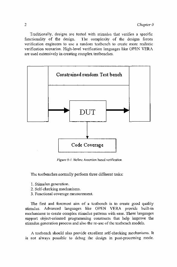
Traditionally, designs are tested with stimulus that verifies a specific functionality of the design. The complexity of the designs forces verification engineers to use a random testbench to create more realistic verification scenarios. High-level verification languages like OPEN VERA are used extensively in creating complex testbenches.
Constrained random Testbench
DUT
Code Coverage
Figure O-l. Before Assertion based verification
The testbenches normally perform three different tasks:
1. Stimulus generation. 2. Self-checking mechanisms. 3. Functional coverage measurement.
The first and foremost aim of a testbench is to create good quality stimulus. Advanced languages like OPEN VERA provide built-in mechanisms to create complex stimulus patterns with ease. These languages support object-oriented programming constructs that help improve the stimulus generation process and also the re-use of the testbench models.
A testbench should also provide excellent self-checking mechanisms. It is not always possible to debug the design in post-processing mode.

0. Assertion based Verification 3
Mechanisms like waveform debugging are prone to human error and are also not very feasible with the complex designs of today. Every test should have a way of checking the expected results automatically and dynamically. This will make the debugging process easy and also make the regression tests more efficient. Self-checking processes usually targets two specific areas:
1. Protocol checking 2. Data checking
Protocol checking targets the control signals. The validity of the control signals is the heart of any design verification. Data checking deals with the integrity of the data being dealt with. For example, are the packets getting transferred without corruption in a networking design? Data-checking normally requires some level of formatting and massaging that is usually taken care of within the testbench environment effectively.
Functional coverage provides a measure of verification completeness. The measurement should contain information on two specific items:
1. Protocol coverage 2. Test plan coverage
Protocol coverage gives a measure on exercising the design for all valid and invalid design conditions. In other words, it is a measure against the functional specification of the design that confirms that all possible functionality has been tested. Test plan coverage, on the other hand, measures the exhaustiveness of the testbench. For example, did the testbench create all possible packet sizes, did the CPU write or read to all possible memory address spaces? Protocol coverage is measured directly from the design signals, and the test plan coverage can be easily measured with built-in methods within the testbench environment.
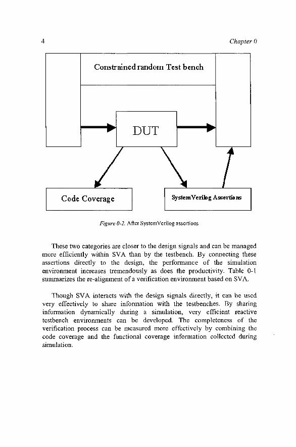
SystemVerilog assertions modify the verification environment in a manner such that the strengths of different entities are leveraged to the maximum. Figure 0-2 shows the modified block diagram for the verification environment that includes Assertion Based Verification (ABV).
There are two categories discussed in the different pieces of the testbench, which are addressed in detail by SystemVerilog assertions (SVA):
1. Protocol checking 2. Protocol coverage
Chapter 0
Constrained random Test bench
DUT
Code Coverage SystemVerllDg Assertions
Figure 0-2. After SystemVerilog assertions
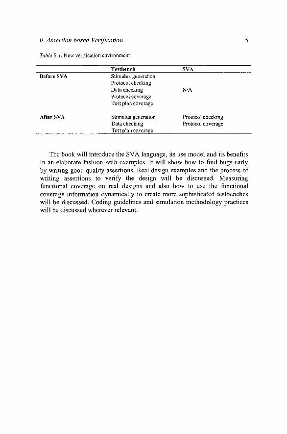
These two categories are closer to the design signals and can be managed more efficiently within SVA than by the testbench. By connecting these assertions directly to the design, the performance of the simulation environment increases tremendously as does the productivity. Table 0-1 summarizes the re-alignment of a verification environment based on SVA.
Though SVA interacts with the design signals directly, it can be used very effectively to share information with the testbenches. By sharing information dynamically during a simulation, very efficient reactive testbench environments can be developed. The completeness of the verification process can be measured more effectively by combining the code coverage and the functional coverage information collected during simulation.
0. Assertion based Verification
Table 0-1, New verification environment
Testbench SVA Before SVA
After SVA
Stimulus generation Protocol checking Data checking Protocol coverage Test plan coverage
Stimulus generation Data checking Test plan coverage
N/A
Protocol checking Protocol coverage
The book will introduce the SVA language, its use model and its benefits in an elaborate fashion with examples. It will show how to find bugs early by writing good quality assertions. Real design examples and the process of writing assertions to verify the design will be discussed. Measuring functional coverage on real designs and also how to use the functional coverage information dynamically to create more sophisticated testbenches will be discussed. Coding guidelines and simulation methodology practices will be discussed wherever relevant.
Chapter 1
INTRODUCTION TO SVA Understanding the Syntax
1.1 What is an Assertion?
An assertion is a description of a property of the design.
• If a property that is being checked for in a simulation does not behave the way we expect it to, the assertion fails.
• If a property that is forbidden from happening in a design happens during simulation, the assertion fails.
A list of the properties can be inferred from the functional specification of a design and can be converted into assertions. These assertions can be continuously monitored during functional simulations. The same assertions can also be re-used for verifying the design using formal techniques. Assertions, also known as monitors or checkers, have been used as a form of debugging technique for a very long time in the design verification process. Traditionally, they are written in a procedural language like Verilog. They can also be written in PLI and C/C++ programs. The following code shows a simple mutually asserted condition check written in Verilog, wherein signal "a" and signal "b" cannot be high at the same time. If they are, an error message is displayed.
"ifdef ma if(a & b) $display
Chapter 1
{"Error:Mutually asserted check failed\n") "endif
This kind of a monitor is included only as part of the simulation and hence is included in the design environment only on a need basis. This can be accomplished with the Mfdef construct which enables conditional compilation of Verilog code.
1.2 Why use SystemVerilog Assertions (SVA)?
While Verilog language can be used to write certain checks easily, it has a few disadvantages.
1. Verilog is a procedural language and hence, does not have good control over time.
2. Verilog is a verbose language. As the number of assertions increase, it becomes very difficult to maintain the code.
3. The procedural nature of the language makes it difficult to test for parallel events in the same time period. In some cases, it is also possible that a Verilog checker might not capture all the triggered events.
4. Verilog language has no built-in mechanism to provide functional coverage data. The user has to produce this code.
SVA is a declarative language and is perfectly suited for describing temporal conditions. The declarative nature of the language gives excellent control over time. The language itself is very concise and is very easy to maintain. SVA also provides several built-in functions to test for certain design conditions and also provides constructs to collect functional coverage data automatically.
Example 1.1 shows a checker written both in Verilog and SVA. The checker verifies that if signal "a" is high in the current clock cycle, then signal "b" should be high within 1 to 3 clock cycles. Figure 1-1 shows the waveform of a sample simulation of the signals "a" and "b."
Example 1.1 Sample assertion written in Verilog and SVA
// Sample Verilog checker
always ©{posedge a) begin

1. Introduction to SVA 9
repeat (1) ©(posedge elk); fork: a_to_b
begin ©(posedge b) $display ("SUCCESS: b arrived in time\n", $time); disable a_to_b; end
begin repeat (3) ©(posedge elk); $display ("ERROR:b did not arrive in time\n", $time); disable a_to_b; end
join end
// SVA Checker
a_to_b_chk: assert property ©(posedge e l k ) $ r o s e ( a ) | - > # # [ 1 : 3 ] $ r o s e { b ) ) ;
1 2 3 4 5 6 7 8 9 10 11 1213 141516 17 18
n Figure 1-1. Waveform for sample assertion
Example 1.1 shows the advantages of SVA very clearly. SVA syntax is discussed in detail in this chapter. The checker represents a very simple protocol. It can be written in one line in SVA, although the same protocol description takes several lines in Verilog. Also, the error and success conditions need to be defined in Verilog explicitly, whereas the failure will automatically display an error message in SVA. Results of a sample simulation are shown below.
10 Chapter 1
SUCCESS: b a r r i v e d in t ime 127 v tosva . a_ to_b_chk : started at 125s succeeded at 175s
SUCCESS: b arrived in time 427 vtosva.a_to_b_chk: started at 325s succeeded at 475s
ERROR: b did not arrive in time 775 vtosva.a_to_b_chk: started at 625s failed at 775s
Offending '$rose(b)'
1.3 SystemVerilog Scheduling
The SystemVerilog language is defined to be an event based execution model. In each time slot, many events are scheduled to happen. This list of events follows the algorithm specified by the standard. By following this algorithm, the simulators can avoid any inconsistencies in the interactions between the design and testbench. There are three regions that are involved in the evaluation and execution of the assertions.
Preponed - Values are sampled for the assertion variables in this region. In this region, a net or variable cannot change its state. This allows the sampling of the most stable value at the beginning of the time slot.
Observed - All the property expressions are evaluated in this region.
Reactive - The pass/fail code from the evaluation of the properties are scheduled in this region.
Figure 1-2 shows a simplified SystemVerilog event schedule flow chart. To understand the SystemVerilog scheduling algorithm thoroughly, please refer to the SystemVerilog 3.1a LRM [1].