a powerful ipsec multi-tunnels architecture · including its architecture, ... ipsec implementation...
TRANSCRIPT
Abstract—This paper aims to introduce IPSec protocol,
including its architecture, protocols family and implementations.
We propose a performance evaluation setup which allows IPSec
implementers to evaluate their IPSec implementation. IPSec as it
is known as a set of protocols that work together, with utilizing
multiple components in the IPSec architecture to serve one
purpose, which is securing the internet Protocol (IP) packets.
Security services provided by IPSec in general include:
confidentiality, integrity check and authenticity of the data.
Since measuring the performance can vary and this variation
would end up in inconsistent measuring. This paper represents a
good methodology to test IPSec performance and introduces a
powerful IPSec architecture that utilizes multi-tunnels.
Index Terms—IPSec, StrongSwan, IKE, styling, insert.
I. INTRODUCTION
In Internet Protocol Security (IPSec), users can
communicate through public networks such as internet with
having their connection secure. This secure IPSec tunnel can
be built between host-to-host or between site-to-site, that
tunnel is a one kind of Virtual Private Networks (VPN) as the
name suggests, Virtual because it is a tunnel that has been
constructed by using multiple hops along a public network
such as internet; it is Private since encryption has been used
which transfers that data from being public data into private
data even though it is transferred through a public medium;
and well, it is Networks because it is working as a topology of
interconnected computers that may constitute a huge
networks or network of networks. Not only IPSec, but many
other protocols can build a VPN. Widely accepted and widely
used protocols such as Secure Sockets Layer (SSL), Transport
Layer Security (TLS) and Secure Shell (SSH). Big difference
between these protocols and between IPSec, is that IPSec
operates at the third layer at TCP/IP stack which known as
Network Layer whereas the other protocols operates at the
fourth and the fifth layer Transport Layer and Applications
Layer in the TCP/IP stack. The paper is organized as follows:
first, we talk about the standard IPSec architecture in Section
II. In Section III, we talk about the IPSec implementation. In
Section IV, we show the authentication header. Strong Swan
is illustrated in Section V. In Section VI, a performance
evaluation is shown. Related work is presented in Section VII.
IPSec multi-tunnels architecture is depicted in Section VIII.
Finally, we talk about the conclusions and the future work in
Section IX.
Manuscript received January 23, 2014; revised April 24, 2014. This work
was supported in part by King Saud University, Department of Computer
Science, Saudi Arabia.
The authors are with the Department of Computer Science, King Saud
University, Saudi Arabia (e-mail: [email protected],
II. IPSEC ARCHITECTURE
Speaking of IPSec architecture involves listing all of the
components that contained in IPSec specification. As IETF
has provided 12 RFC documents for IPSec protocol, there is
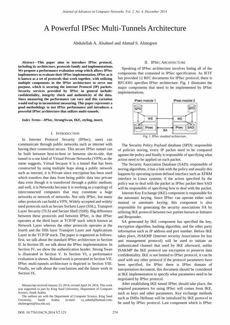
RFC4301 specifies IPSec architecture. Fig. 1 illustrates the
major components that need to be implemented by IPSec
implementations.
Fig. 1. IPSec standard architecture.
The Security Policy Payload database (SPD): responsible
of policies storing, every IP packet need to be compared
against the policy and finally it responsible of specifying what
action need to be applied on each packet.
The Security Association Database (SAD): responsible of
storing algorithms, it has a link with the policy and usually this
happens by operating system defined interface such as XFRM
interface in Linux systems; if the action specified by the
policy was to deal with the packet as IPSec packet then SAD
will be responsible of specifying how to deal with the packet.
Internet Key Exchange (IKE) component is responsible for
the automatic keying. Since IPSec can operate either with
manual or automatic keying; this component is also
responsible for generating the security associations SA by
utilizing IKE protocol between two parties known as Initiator
and Responder.
SA generated by IKE component has specified the key,
encryption algorithm, hashing algorithm, and the other party
information such as IP address and port number. Before IKE
takes place, ISAKMP (Internet security Association for key
and management protocol) will be used to initiate an
authenticated channel that used by IKE afterward, unlike
ISAKMP the IKE protocol use encryption to preserve data
confidentiality. IKE is not limited to IPSec protocol, it can be
used with any other protocol if the protocol parameters have
been specified, for IPSec there is IPSec domain of
interpretation document, this document should be considered
at IKE implementation to specify what parameters need to be
negotiated by IPSec protocol.
After establishing IKE tunnel IPSec should take place, the
required parameters for using IPSec will comes from IKE,
such as keys and other parameters. Key exchange methods
such as Diffie Hellman will be initialized by IKE protocol to
be used by IPSec protocol. Last component which is IPSec
A Powerful IPSec Multi-Tunnels Architecture
Abdulellah A. Alsaheel and Ahmad S. Almogren
Journal of Advances in Computer Networks, Vol. 2, No. 4, December 2014
274DOI: 10.7763/JACN.2014.V2.125
base protocol, which is responsible for handling outbound and
inbound IPSec packets, this component takes place in the
TCP/IP stack and usually it has a user interface that used to
control or to monitor the IPSec implementation. IPSec base
protocol component implements two protocols
Authentication header (AH) and Encapsulated Security
Payload (ESP). AH protocol provides data authenticity and
integrity. On the other hand ESP provides data encryption and
authenticity and integrity as optional. Sometimes AH is used
to protect ESP, this approach will offer ultimate data integrity
since AH is unlike of ESP is calculating the Integrity
Checking Value (ICV) with considering the IP header
whereas ESP consider its header and the IP payload only.
III. IPSEC IMPLEMENTATION
IPSec has two forms of implementation. Either it is
implemented in host machine or in a gateway router, each of
which has its own advantages. The host implementation [1]
guarantees end to end protection, implement tunnel and
transport IPSec modes, protection is per flow where each flow
will be protected as specified in the policy. Host
implementation is classified as native or shim. As the native is
natively integrated with the host operating system and it
comes bundled at the TCP/IP stack, where on the other hand
there is shim implementation which is added by IPSec
implementers into the TCP/IP stack between the network
layer and the data link layer, this usually known as Bump In
the Stack (BITS). As the native implementation has numerous
advantages over the shim implementation since it can utilize
network services such as path maximum transfer unit (PMTU),
fragmentation and many other services provided by network
layer. On the other hand shim implementation need add its
own services which mean increasing implementation
complexity and duplication of already implemented services
in the network layer.
For gateway routers implementation they utilize tunneling
mode only since many hosts behind them transferring data to
the remote site. Same as host implementation, router
implementation can be either native implementation means
the IPSec implementation is natively implemented in the
TCP/IP stack of the router. The other type of the router
implementation is Bump In The Wire (BITW) which is
similar to the bump in the stack, BITW is a hardware
implementation that attached to the router interface
responsible for applying IPSec services on the routed packets.
Possible performance improvements for IPSec
implementations is to use hardware approaches to improve
IPSec performance, such as using dedicated chip for
generating keys or random numbers, or to use special
hardware for calculating hash values or to encrypt or decrypt
data.
IV. AUTHENTICATION HEADER
In addition to data authenticity and integrity, AH provides
replay protection. It places its header between IP header and
IP payload. AH uses Hash Message Authentication Code
(HMAC) to enforce its protection. Encapsulated Security
Payload (ESP) protects packets by applying encryption,
authentication and optionally data integrity if a trailer gets
added at the end of the packet, which utilizes HMAC
calculations. Its header gets placed between the IP header and
the IP payload.
V. STRONGSWAN
StrongSwan is one of the most prominent IPSec
implementations, extra credits for StrongSwan over other
IPSec implementation such as OpenSwan, FreeS/Wan and
KAME-Tools. Is that StrongSwan is widely adapted in
different Linux distributions, and it is up to this date receives
new releases. It has many plug-ins and it is well documented.
StrongSwan requires enabling some kernel options which are
[2]:
[CONFIG_XFRM_USER],[CONFIG_NET_KEY],
[CONFIG_INET],[CONFIG_IP_ADVANCED_ROUTER],
[CONFIG_IP_MULTIPLE_TABLES],[CONFIG_INET_A
H], [CONFIG_INET_ESP],[CONFIG_INET_IPCOMP],
[CONFIG_INET_XFRM_MODE_TRANSPORT],
[CONFIG_INET_XFRM_MODE_TUNNEL],
[CONFIG_INET_XFRM_MODE_BEET],
[CONFIG_NETFILTER_XTABLES],
[CONFIG_NETFILTER_XT_MATCH_POLICY].
StrongSwan has a set of tools and libraries that constitute
its architecture, StrongSwan components are listed as follows
[3]:
1) charon: component that implements IKE protocol
keying.
2) libstrongswan: the base component that provide the basic
functions used by the tool.
3) libcharon: provide the main functions for IKE to be used
by charon component.
4) libhydra: provide daemon services for charon tool.
5) dumm: testing framework.
6) ipsec: command line interface that let user control and
monitor IPSec functions.
7) manager: web interface to control and monitor charon by
using libfast.
8) libfast: framework to build web applications, this to
provide web interface that control and monitor
StrongSwan.
9) openac: tool to generate certificates attributes.
10) pki: public key infrastructure tool.
11) scepclient: client that implements SCEP protocol that
check the certificates enrollment.
12) starter: responsible for handling ipsec.conf file and of the
keying process.
13) stroke: command line tool that controls charon through
stroke protocol.
A. IPSec Architecture at StrongSwan
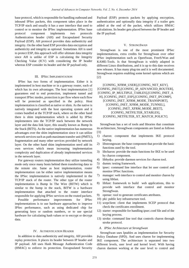
StrongSwan uses Iptables as implementation for Security
Policy Database (SPD). And uses charon for implementing
IKE component. The architecture is separated into two
different levels, user level and kernel level. With having
charon daemon working at the user level to control and
Journal of Advances in Computer Networks, Vol. 2, No. 4, December 2014
275
manage Security Associations (SAs) on the use demand. And
it has the kernel level where NETKEY utilized, which
typically deals with encryption and decryption, re-keying and
SAs. The IPSec architecture is illustrated at Fig. 2.
Fig. 2. StrongSwan architecture.
As the majority of IPSec implementations, StrongSwan
uses virtual interface to deal with IPSec packets, there is no
difference between the virtual interface [4] and the physical
interface except that the virtual interface cannot send data to
the public networks, in Linux systems this usually referred to
as TUN/TAP. For IPSec packets first it needs to be processed
by the virtual interface then it needs to be send back to the
physical interface to be treated as normal IP packet.
VI. STRONG SWAN PERFORMANCE EVALUATION
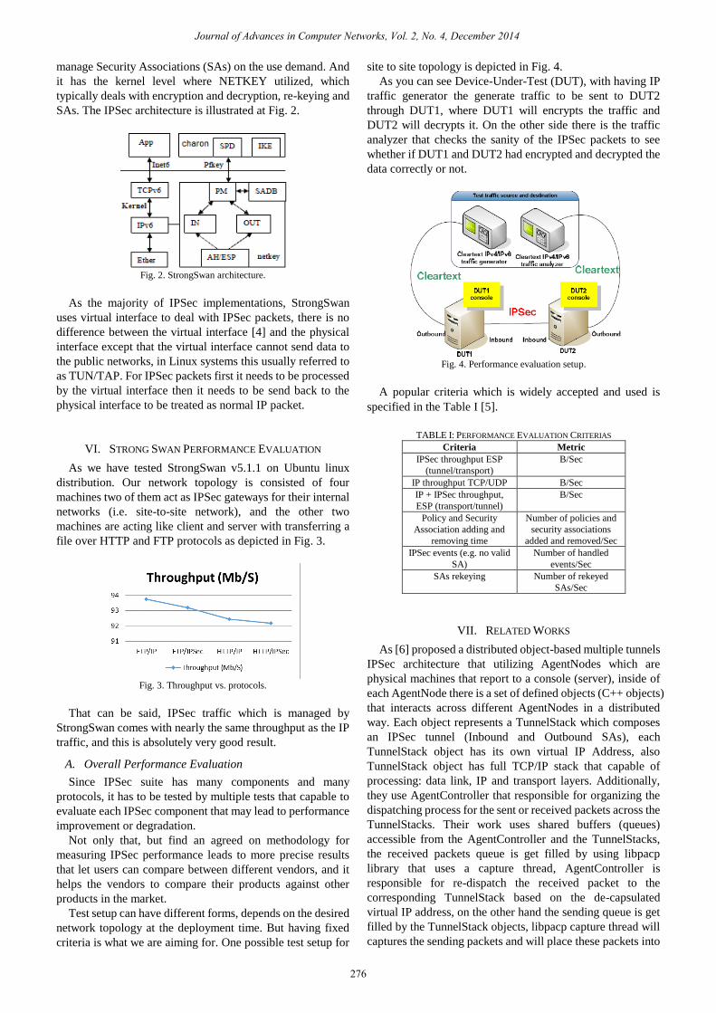
As we have tested StrongSwan v5.1.1 on Ubuntu linux
distribution. Our network topology is consisted of four
machines two of them act as IPSec gateways for their internal
networks (i.e. site-to-site network), and the other two
machines are acting like client and server with transferring a
file over HTTP and FTP protocols as depicted in Fig. 3.
Fig. 3. Throughput vs. protocols.
That can be said, IPSec traffic which is managed by
StrongSwan comes with nearly the same throughput as the IP
traffic, and this is absolutely very good result.
A. Overall Performance Evaluation
Since IPSec suite has many components and many
protocols, it has to be tested by multiple tests that capable to
evaluate each IPSec component that may lead to performance
improvement or degradation.
Not only that, but find an agreed on methodology for
measuring IPSec performance leads to more precise results
that let users can compare between different vendors, and it
helps the vendors to compare their products against other
products in the market.
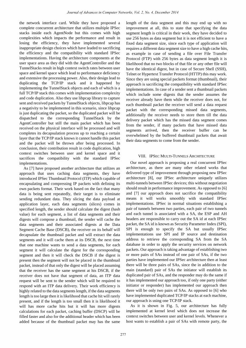
Test setup can have different forms, depends on the desired
network topology at the deployment time. But having fixed
criteria is what we are aiming for. One possible test setup for
site to site topology is depicted in Fig. 4.
As you can see Device-Under-Test (DUT), with having IP
traffic generator the generate traffic to be sent to DUT2
through DUT1, where DUT1 will encrypts the traffic and
DUT2 will decrypts it. On the other side there is the traffic
analyzer that checks the sanity of the IPSec packets to see
whether if DUT1 and DUT2 had encrypted and decrypted the
data correctly or not.
Fig. 4. Performance evaluation setup.
A popular criteria which is widely accepted and used is
specified in the Table I [5].
TABLE I: PERFORMANCE EVALUATION CRITERIAS
Criteria Metric
IPSec throughput ESP
(tunnel/transport)
B/Sec
IP throughput TCP/UDP B/Sec
IP + IPSec throughput,
ESP (transport/tunnel)
B/Sec
Policy and Security
Association adding and
removing time
Number of policies and
security associations
added and removed/Sec
IPSec events (e.g. no valid
SA)
Number of handled
events/Sec
SAs rekeying Number of rekeyed
SAs/Sec
VII. RELATED WORKS
As [6] proposed a distributed object-based multiple tunnels
IPSec architecture that utilizing AgentNodes which are
physical machines that report to a console (server), inside of
each AgentNode there is a set of defined objects (C++ objects)
that interacts across different AgentNodes in a distributed
way. Each object represents a TunnelStack which composes
an IPSec tunnel (Inbound and Outbound SAs), each
TunnelStack object has its own virtual IP Address, also
TunnelStack object has full TCP/IP stack that capable of
processing: data link, IP and transport layers. Additionally,
they use AgentController that responsible for organizing the
dispatching process for the sent or received packets across the
TunnelStacks. Their work uses shared buffers (queues)
accessible from the AgentController and the TunnelStacks,
the received packets queue is get filled by using libpacp
library that uses a capture thread, AgentController is
responsible for re-dispatch the received packet to the
corresponding TunnelStack based on the de-capsulated
virtual IP address, on the other hand the sending queue is get
filled by the TunnelStack objects, libpacp capture thread will
captures the sending packets and will place these packets into
Journal of Advances in Computer Networks, Vol. 2, No. 4, December 2014
276
the network interface card. While they have proposed a
complete concurrent architecture that utilizes multiple IPSec
stacks inside each AgentNode but this comes with high
complexities which impacts the performance and result in
losing the efficiency, they have implemented several
inappropriate design choices which have leaded to sacrificing
the efficiency and the compatibility with standard IPSec
implementations. Having the architecture components at the
user space area as they did with the AgentController and the
TunnelStacks result in high context switch rates between user
space and kernel space which lead to performance deficiency
and extensive the processing power. Also, their design lead to
duplicating the TCP/IP stack and it happened by
implementing the TunnelStack objects and each of which is a
full TCP/IP stack this comes with implementation complexity
and code duplication. Also they use libpcap library to capture
sent and received packets by TunnelStack objects, libpcap has
a negativity to be implemented in this scenario, since libpcap
is just duplicating the packet, so the duplicated packet will be
dispatched to the corresponding TunnelStack by the
AgentController but still the main packet which has been
received on the physical interface will be processed and will
completes its decapsulation process up to reaching a certain
layer that the TCP/IP stack knows it cannot handle this packet
and the packet will be thrown after being processed. In
conclusion, their contribution result in code duplication, high
context switches between user and kernel space and it
sacrifices the compatibility with the standard IPSec
implementations.
As [7] have proposed another architecture that utilizes an
approach that uses caching data segments, they have
introduced IPSec Thumbnail Protocol (ITP) which capable of
encapsulating and compressing IP packets with defining its
own packets format. Their work based on the fact that many
data is being sent repeatedly, their target is to eliminate
sending redundant data. They slicing the data payload at
application layer, each data segments (slices) comes in
specified length, the sender should calculate the digest (hash
value) for each segment, a list of data segments and their
digests will compose a thumbnail, the sender will cache the
data segments and their associated digests at the Data
Segment Cache Base (DSCB), the receiver on its behalf will
decapsulate the thumbnail packet and will extract the data
segments and it will cache them at its DSCB, the next time
that one machine wants to send a data segments, for each
segment it will calculate the digest for the corresponding
segment and then it will check the DSCB if the digest is
present then the segment will not be placed in the thumbnail
packet, instead of that only the digest will be placed assuming
that the receiver has the same segment at his DSCB, if the
receiver does not have that segment of data, an ITP data
request will be sent to the sender which will be required to
respond with an ITP data delivery. Their work efficiency is
highly related to the data segments length, if the data segments
length is too large then it is likelihood that cache hit will rarely
present, and if the length is too small then it is likelihood it
will has more cache hits but it will has more digests
calculations for each packet, caching buffer (DSCP) will be
filled faster and also for the additional header which has been
added because of the thumbnail packet may has the same
length of the data segment and this may end up with no
improvement at all, this to state that specifying the data
segment length is critical in their work, they have decided to
use 256 bytes as data segment but it is not efficient to have a
fixed data segment size, since each type of application will
requires a different data segment size to have a high cache hits,
as example in case of sending a file over File Transfer
Protocol (FTP) with 256 bytes as data segment length it is
likelihood that no two blocks of that file or any other file will
have the identical digest, but in case of Secure Shell (SSH),
Telnet or Hypertext Transfer Protocol (HTTP) this may work.
Since they are using special packets format (thumbnail), their
approach is sacrificing the compatibility with standard IPSec
implementations. In case of a sender sent a thumbnail packets
which include some digests that the sender assumes the
receiver already have them while the receiver does not, for
each thumbnail packet the receiver will send a data request
packet with the corresponding missed data segments,
additionally the receiver needs to store them till the data
delivery packet which has the missed data segment comes
from the sender, if many packets that have missed data
segments arrived, then the receiver buffer can be
overwhelmed by the buffered thumbnail packets that await
their data segments to come from the sender.
VIII. IPSEC MULTI-TUNNELS ARCHITECTURE
Our novel approach is proposing a real concurrent IPSec
architecture, as there are many other related works that
delivered type of improvement through proposing new IPSec
architecture [8], our IPSec architecture uniquely utilizes
multi-tunnels between IPSec devices; this without negotiation
should result in performance improvement. As opposed to [6]
and [7] our approach does not sacrifice the compatibility
means it will works smoothly with standard IPSec
implementations. IPSec in normal situations establishing a
pair of tunnels between two parties, each pair of two tunnels
and each tunnel is associated with a SA, the ESP and AH
headers are responsible to carry out the SA id at each IPSec
packet, the SA id is known as Security Parameter Index (SPI),
SPI is enough to specify the SA but usually IPSec
implementations use SPI and IP source and destination
address to retrieve the corresponding SA from the SA
database in order to apply the security services on network
packets. Our approach is taking advantage of establishing two
or more pairs of SAs instead of one pair of SAs, if the two
parties have implemented our IPSec architecture then at least
there will be three pairs of SAs, since the in addition to the
main (standard) pair of SAs the initiator will establish its
duplicated pair of SAs, and the responder may do the same if
it has implemented our approach too, if only one party (either
initiator or responder) has implemented our approach then
there will be only two pairs of SAs. As opposed to [6] who
have implemented duplicated TCP/IP stacks at each machine,
our approach is using one TCP/IP stack.
As it is shown in Fig. 5, our architecture has fully
implemented at kernel level which does not increase the
context switches between user and kernel levels. Whenever a
host wants to establish a pair of SAs with remote party, the
Journal of Advances in Computer Networks, Vol. 2, No. 4, December 2014
277
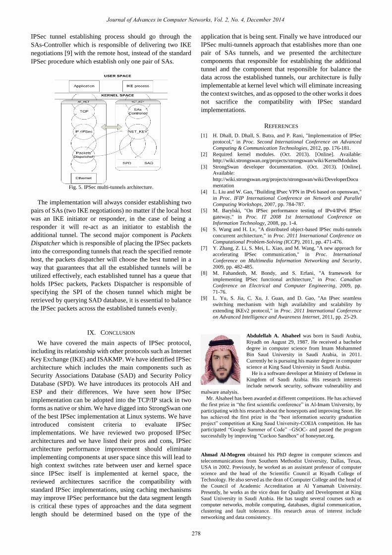
IPSec tunnel establishing process should go through the
SAs-Controller which is responsible of delivering two IKE
negotiations [9] with the remote host, instead of the standard
IPSec procedure which establish only one pair of SAs.
Fig. 5. IPSec multi-tunnels architecture.
The implementation will always consider establishing two
pairs of SAs (two IKE negotiations) no matter if the local host
was an IKE initiator or responder, in the case of being a
responder it will re-act as an initiator to establish the
additional tunnel. The second major component is Packets
Dispatcher which is responsible of placing the IPSec packets
into the corresponding tunnels that reach the specified remote
host, the packets dispatcher will choose the best tunnel in a
way that guarantees that all the established tunnels will be
utilized effectively, each established tunnel has a queue that
holds IPSec packets, Packets Dispatcher is responsible of
specifying the SPI of the chosen tunnel which might be
retrieved by querying SAD database, it is essential to balance
the IPSec packets across the established tunnels evenly.
IX. CONCLUSION
We have covered the main aspects of IPSec protocol,
including its relationship with other protocols such as Internet
Key Exchange (IKE) and ISAKMP. We have identified IPSec
architecture which includes the main components such as
Security Associations Database (SAD) and Security Policy
Database (SPD). We have introduces its protocols AH and
ESP and their differences. We have seen how IPSec
implementation can be adopted into the TCP/IP stack in two
forms as native or shim. We have digged into StrongSwan one
of the best IPSec implementation at Linux systems. We have
introduced consistent criteria to evaluate IPSec
implementations. We have reviewed two proposed IPSec
architectures and we have listed their pros and cons, IPSec
architecture performance improvement should eliminate
implementing components at user space since this will lead to
high context switches rate between user and kernel space
since IPSec itself is implemented at kernel space, the
reviewed architectures sacrifice the compatibility with
standard IPSec implementations, using caching mechanisms
may improve IPSec performance but the data segment length
is critical these types of approaches and the data segment
length should be determined based on the type of the
application that is being sent. Finally we have introduced our
IPSec multi-tunnels approach that establishes more than one
pair of SAs tunnels, and we presented the architecture
components that responsible for establishing the additional
tunnel and the component that responsible for balance the
data across the established tunnels, our architecture is fully
implementable at kernel level which will eliminate increasing
the context switches, and as opposed to the other works it does
not sacrifice the compatibility with IPSec standard
implementations.
REFERENCES
[1] H. Dhall, D. Dhall, S. Batra, and P. Rani, "Implementation of IPSec
protocol," in Proc. Second International Conference on Advanced
Computing & Communication Technologies, 2012, pp. 176-181.
[2] Required kernel modules. (Oct. 2013). [Online]. Available:
http://wiki.strongswan.org/projects/strongswan/wiki/KernelModules
[3] StrongSwan developer documentation. (Oct. 2013). [Online].
Available:
http://wiki.strongswan.org/projects/strongswan/wiki/DeveloperDocu
mentation
[4] L. Liu and W. Gao, "Building IPsec VPN in IPv6 based on openswan,"
in Proc. IFIP International Conference on Network and Parallel
Computing Workshops, 2007, pp. 784-787.
[5] M. Barylski, "On IPSec performance testing of IPv4/IPv6 IPSec
gateway," in Proc. IT 2008 1st International Conference on
Information Technology, 2008, pp. 1-4.
[6] S. Wang and H. Lv, "A distributed object-based IPSec multi-tunnels
concurrent architecture," in Proc. 2011 International Conference on
Computational Problem-Solving (ICCP), 2011, pp. 471-476.
[7] Y. Zhang, Z. Li, S. Mei, L. Xiao, and M. Wang, "A new approach for
accelerating IPSec communication," in Proc. International
Conference on Multimedia Information Networking and Security,
2009, pp. 482-485.
[8] M. Fahandezh, M. Bondy, and S. Erfani, "A framework for
implementing IPSec functional architecture," in Proc. Canadian
Conference on Electrical and Computer Engineering, 2009, pp.
71-76.
[9] L. Yu, S. Jia, C. Xu, J. Guan, and D. Gao, "An IPsec seamless
switching mechanism with high availability and scalability by
extending IKEv2 protocol," in Proc. 2011 International Conference
on Advanced Intelligence and Awareness Internet, 2011, pp. 25-29.
Abdulellah A. Alsaheel was born in Saudi Arabia,
Riyadh on August 29, 1987. He received a bachelor
degree in computer science from Imam Mohammed
Bin Saud University in Saudi Arabia, in 2011.
Currently he is pursuing his master degree in computer
science at King Saud University in Saudi Arabia.
He is a software developer at Ministry of Defense in
Kingdom of Saudi Arabia. His research interests
include network security, software vulnerability and
malware analysis.
Mr. Alsaheel has been awarded at different competitions. He has achieved
the first prize in “the first scientific conference” in Al-Imam University, by
participating with his research about the honeypots and improving Snort. He
has achieved the first prize in the “best information security graduation
project” competition at King Saud University-COEIA competition. He has
participated “Google Summer of Code” –GSOC- and passed the program
successfully by improving "Cuckoo Sandbox" of honeynet.org.
Ahmad Al-Mogren obtained his PhD degree in computer sciences and
telecommunications from Southern Methodist University, Dallas, Texas,
USA in 2002. Previously, he worked as an assistant professor of computer
science and the head of the Scientific Council at Riyadh College of
Technology. He also served as the dean of Computer College and the head of
the Council of Academic Accreditation at Al Yamamah University.
Presently, he works as the vice dean for Quality and Development at King
Saud University in Saudi Arabia. He has taught several courses such as
computer networks, mobile computing, databases, digital communication,
clustering and fault tolerance. His research areas of interest include
networking and data consistency.
Journal of Advances in Computer Networks, Vol. 2, No. 4, December 2014
278