a numerical study of a vibration-driven mechanism of
TRANSCRIPT

A numerical study of a vibration-driven mechanismof propulsion in a viscous fluid
Artem Nuriev, Olga Zaitseva, Olga Zhuchkova
06.12.19
Artem Nuriev, Olga Zaitseva, Olga Zhuchkova A vibration-driven mechanism of propulsion

Introduction. Mechanisms of underwater propulsion at lowReynolds numbers ∼ 101 − 103
”Reactive motion”. Propulsion due to inertial forces
Resestive motion
Artem Nuriev, Olga Zaitseva, Olga Zhuchkova A vibration-driven mechanism of propulsion

Introduction. Forces acting on a sphere during thenon-stationary translational motion
Asymptotic solution for infinity small Reynolds numbers (Basset1888)
F = Cadu
dt+ Ch
∫ t
−∞
du
dτ
dτ√t − τ
+ Cst u.
Moden model for finite Reynolds numbers
F = Fa + Fh + Fst .
Quasi-stationary resistance Fst , added mass force Fa and historyforce Fh.
Artem Nuriev, Olga Zaitseva, Olga Zhuchkova A vibration-driven mechanism of propulsion

Propulsion of a sphere in fluid. Mathematical formulation
Let a spherical body with radius R move in a viscous fluidaccording to a periodic law uM with an average (over the periodT ) velocity uav along the axis Ox . Normalizing the spatialcoordinates, time, and velocity by R, Ruav
−1, uav , respectively, wewrite the system of equations of motion of the fluid around aspherical body in the following form:
∂U
∂t+ U · ∇U = −∇p +
2
Reav∇2U, (1)
∇ · U = 0.
On the boundary of the sphere in the new coordinate systemno-slip conditions are specified:
uS = vS = wS = 0. (2)
At infinity the change of the velocity is given by the law:
u∞ = −uM , v∞ = w∞ = 0. (3)
Artem Nuriev, Olga Zaitseva, Olga Zhuchkova A vibration-driven mechanism of propulsion

The law of a body motion
The acceleration uM of the body is determined by the followingcontinuous piecewise linear function:
uM =δu
c2
0, τ ∈ [0, b]
b − τ, τ ∈ (b, b + c]
τ − b − 2c , τ ∈ (b + c , b + 2c)
0, τ ∈ [b + 2c, 1− 2c]
τ − 1 + 2c , τ ∈ (1− 2c , 1− c]
1− τ, τ ∈ (1− c, 1)
, (4)
a + b + 4c = 1, τ =t
2κ, κ =
T uav2R
, δu = u+ − u−.
Function (4) sets the periodic switching between two phases duringwhich the body moves at constant speeds u+ and u−.
Artem Nuriev, Olga Zaitseva, Olga Zhuchkova A vibration-driven mechanism of propulsion

The condition of steady motion
We assume that the body is in steady motion if the solution ofequations (1)-(4) satisfies the conditions:
〈Fx(uM)〉 = 0, 〈uM〉 = 1. (5)
Here Fx is the force acting on the sphere along the axis ofoscillation, triangular brackets indicate the averaging over theperiod.
Figure : A fragment of the law of acceleration of the sphere
Artem Nuriev, Olga Zaitseva, Olga Zhuchkova A vibration-driven mechanism of propulsion

The calculation of hydrodynamic forces
The calculation of hydrodynamic forces acting on the sphere in thepresented dimensionless formulation is carried out according to theformulas:
F = (Fx ,Fy ,Fz) =2
π
(∫Spnds −
∫Sσ · nds
),
where σ is a viscous stress tensor, S is the surface of the sphere, nis the unit normal vector to the sphere surface. It should be notedthat the force in the moving coordinate system is determined by thefictitious pressure and therefore contains a contribution from theinertial component. This contribution can be calculated as follows:
Ffk =2
πuM
∫Sxnds.
As one can see, this term is a linear function of acceleration, andtherefore cannot influence on the propulsion.
Artem Nuriev, Olga Zaitseva, Olga Zhuchkova A vibration-driven mechanism of propulsion

Numerical scheme
To determine the motion parameters u−, δu that satisfy theconditions (5) for given constants Reav , b, κ the secant methodwas used. At each iteration of secant method the hydrodynamicproblem for determination of F was solved. The scheme wasimplemented on the basis of a free, open source CFD softwareOpenFOAM. The standard mesh for three-dimensional calculationscontained 3.5 · 106 cells, for axisymmetric case mesh with 4.3 · 104
cells was used.
Figure : Three-dimensional mesh structure in the vicinity of the sphere.Artem Nuriev, Olga Zaitseva, Olga Zhuchkova A vibration-driven mechanism of propulsion

Flow structure around the sphere
Calculations show that in the case when the backward phase is veryshort (b � 1), the stability of axisymmetric flow regimes is mainlydetermined by the Reynolds number Re+ calculated on the basis ofthe forward phase speed u+. We conducted the study in the zoneof axisymmetric regimes in the following range of parameters:15 < Reav < 105, 0.6 ≤ κ ≤ 6, 0.04 ≤ b ≤ 0.2. On the boundaryof this parameter range the stability of the flow to thethree-dimensional perturbations was tested using 3D calculations.
Figure : Instantaneous structure of flow for κ = 1.26, Reav = 60,b = 0.08. Isosurfaces of vorticity magnitude.
Artem Nuriev, Olga Zaitseva, Olga Zhuchkova A vibration-driven mechanism of propulsion

Flow structure around the sphere
Figure : Instantaneous flow structure. Vorticity. Time momentsτ = 1/6, 2/6, 3/6, 4/6, 5/6, 1. κ = 2.2,Reav = 47, b = 0.08
Artem Nuriev, Olga Zaitseva, Olga Zhuchkova A vibration-driven mechanism of propulsion

Evaluation of hydrodynamic forces. Accelerated motion
Let consider the variations of the forces acting on the sphereduring one period in the steady motion. For the convenience ofanalysis, we divide the entire period into zones corresponding toaccelerated motion and motion at the constant speeds.
Figure : The structure of hydrodynamic forces in accelerated motionzone. The red solid line indicates the total inline hydrodynamic force Fx ,the blue dash-dotted line represents the component associated with theviscous stresses Fv , the green dash line represents the componentassociated with the pressure distribution Fp. κ = 0.6, Reav = 25,b = 0.08.
Artem Nuriev, Olga Zaitseva, Olga Zhuchkova A vibration-driven mechanism of propulsion

Evaluation of hydrodynamic forces. Accelerated motion
The change of the component Fp(≈ Fx ≈ Fa) is completelydescribed by the effect of the added mass. The values of theaverage coefficient of added mass Ca calculated by the formula (6)at each zone of accelerated motion are very close to theoreticalestimate 0.5.
Ca = 〈38
FpuM− 1〉 ≈ 0.5. (6)
Figure :Fp
uMas a function of time. κ = 0.6, Reav = 25, b = 0.08.
Artem Nuriev, Olga Zaitseva, Olga Zhuchkova A vibration-driven mechanism of propulsion
Evaluation of hydrodynamic forces. Constant speed motion
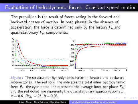
The propulsion is the result of forces acting in the forward andbackward phases of motion. In both phases, in the absence ofacceleration, the force is determined only by the history Fh andquasi-stationary Fst components.
Figure : The structure of hydrodynamic forces in forward and backwardmotion zones. The red solid line indicates the total inline hydrodynamicforce Fx , the cyan doted line represents the average force per phase Fav ,and the red doted line represents the quasistationary approximation Fst .κ = 0.6, Reav = 25, b = 0.08.
Artem Nuriev, Olga Zaitseva, Olga Zhuchkova A vibration-driven mechanism of propulsion

Evaluation of hydrodynamic forces. Constant speed motion
To calculate the force coefficients on the phases, we use thefollowing formulas:
C+/−d = C
+/−h + Cst =
⟨Fx
u+/−|u+/−|
⟩+/−
. (7)
Here the triangular brackets with the index + or − indicate theaveraging of forces over the corresponding phase. The coefficientof the quasistationary component of the force Cst is completelydetermined by the value of the local Reynolds number in phases.
The coefficient of the second component of the force C+/−h
depends on considerably more factors determining the history ofmovement, including phase duration, Re+ and Re−.
Artem Nuriev, Olga Zaitseva, Olga Zhuchkova A vibration-driven mechanism of propulsion

Evaluation of hydrodynamic forces. C+/−d and Cst
Figure : Values of C+/−d for Reav = 47, b = 0.16,
κ = [0.7015, 1.403, 2.1045, 2.806, 5.612] (black markers) and Reav = 47,b = 0.08, κ = [1.09, 2.19, 4.38, 5.48] (blue markers). The arrows indicatethe direction of growth of κ. The black solid line represents the values ofCst .
Artem Nuriev, Olga Zaitseva, Olga Zhuchkova A vibration-driven mechanism of propulsion

The efficiency of the propulsion mechanism
We introduce the indicator of the efficiency η as the ratio of powers
η =N0
Nvbr, (8)
where N0 is the minimum power needed to move the body atspeed uav and Nvbr is the power required by the propulsor to drivethe body at this speed under steady-state conditions.
Figure : Efficiency of the propulsion mechanism. Reav = 47, b = 0.16,κ = [0.7015, 1.403, 2.1045, 2.806, 5.612] (black markers) and Reav = 47,b = 0.08, κ = [1.09, 2.19, 4.38, 5.48] (blue markers). The lines representsthe estimates of theoretical efficiency.
Artem Nuriev, Olga Zaitseva, Olga Zhuchkova A vibration-driven mechanism of propulsion

The efficiency of the propulsion mechanism
Figure : The efficiency of motion as a function of the phase duration.Black lines with markers represent numerical simulation data: KC = 2.2,Re = 47 (round markers), KC = 2.2, Re = 102 (triangular markers) andKC = 4.4, Re = 47 (square markers).
Artem Nuriev, Olga Zaitseva, Olga Zhuchkova A vibration-driven mechanism of propulsion