a ntenna m odeling for b eginners jonathan woo w6gx june 27 2013
TRANSCRIPT
ANTENNA MODELING FOR BEGINNERS
Jonathan Woo W6GXJune 27 2013

Why antenna modeling?

Why antenna modeling?• Which antenna would be the best choice given
your QTH/XYL/budget constraints.• Antenna home-brewing.• Antenna shopping- performance
comparison/validation.• Multi-band antennas- check performance by band.• Determine effects of raising or lowering an
antenna.• Check interactions on multiple antenna
installations.• Saves time, money, and frustration.

Why antenna modeling?
Brings objectivity to a very complex problem
And it’s easier than ever

HOW TO GET STARTED
NEC (neck)- a modeling engine• NEC stands for Numerical Electromagnetics
Code. Dates back to the 1970’s and written in Fortran.
• NEC engine hasn’t been updated. However modeling tools such as EZNEC continues to advance.
• EZNEC is a modeling tool that uses the modeling engine NEC. Many other modeling tools are available, some are free-of-charge and some are not. The use of the engine NEC-2 is free (public domain).

EZNEC (EZ neck)- a modeling tool• Most popular antenna modeling tool
(www.eznec.com)• ARRL free version- unlimited use only on ARRL
data files. Comes with the ARRL antenna hand book CD.
• Free trial version- unlimited use on any data file however limited to 20 wire segments.
• EZNEC v. 5.0- $89; EZNEC+ v. 5.0 $139; EZNEC Pro v. 5.0 $650+
• Other free modeling tools are available such as 4nec2 (http://www.qsl.net/4nec2/)

ANTENNA MODELING BASICS
EZNEC Basics
• Wires- antennas are modeled as a collection of wires, whether the actual antenna is made of wires, rods, tubing, solid surface, or towers. Anything that radiates need to be defined as a wire or collection of wires. A classic dipole could be modeled as one wire.
• Segments- tells EZNEC how to divide up the wire for its calculations. Each segment has equal current and other electrical properties in the model. Affects model accuracy.

EZNEC Basics

EZNEC Basics
• Wire loss- specify the wire resistance by selecting wire material (i.e. aluminum, copper, etc.)
• Wire diameter- potential impact on modeling output. Different wire diameters necessitates modeling each wire separately.

EZNEC Basics
• Sources- bring voltage or current to the wire, aka as a feedpoint. Needs to be placed at the center of a segment.
EZNEC Basics
• Ground types- free space, perfect, or real ground
• Loads- lumped impedance (i.e. loading coils, traps, etc.) Three types- R + jX, RLC, and Laplace transform polynomials.
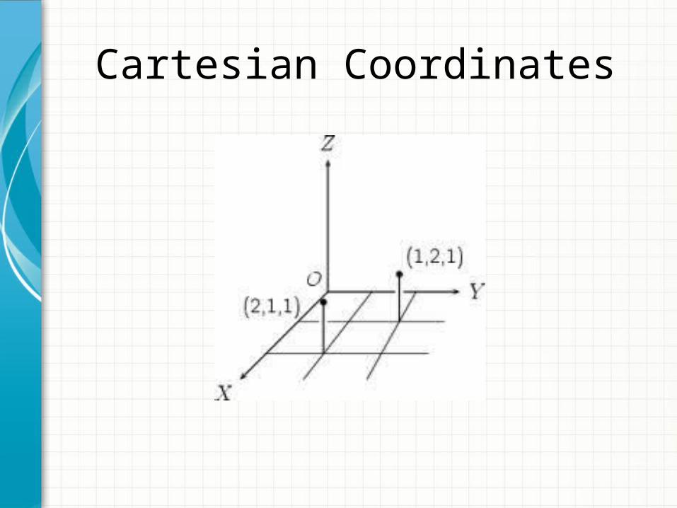
Cartesian Coordinates
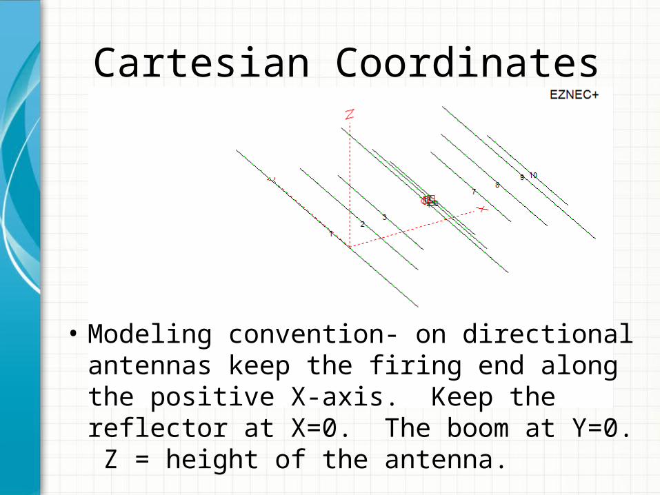
Cartesian Coordinates
• Modeling convention- on directional antennas keep the firing end along the positive X-axis. Keep the reflector at X=0. The boom at Y=0. Z = height of the antenna.

Interpreting the Results• Currents- checking antenna’s operation and
to validate the model• Source data- impedance, SWR, RMS V/I• Far field plots- 2D azimuth (aka polar plot),
2D elevation, 3D.– Gain, beamwidth, F/R, F/S, lobes.
• Antenna efficiency- calculates radiation efficiency
• SWR sweep

Modeling a 20m Dipole @ 30’
• L (length in feet) = 468 / f (frequency in Mhz) = 468 / 14.2 = 32.96’.

Modeling a 20m Dipole @ 30’

LIVE DEMO