a novel training system of lathe works on virtual ... · abstract in recent years virtual reality...
TRANSCRIPT
J. Software Engineering & Applications, 2010, 3: 287-302 doi:10.4236/jsea.2010.33035 Published Online March 2010 (http://www.SciRP.org/journal/jsea)
Copyright © 2010 SciRes. JSEA
287
A Novel Training System of Lathe Works on Virtual Operating Platform
Hui-Chin Chang
Department of Mechanical Engineering, De Lin Institute of Technology, Taipei, Taiwan, China.
Email: [email protected] Received October 19th, 2009; revised November 11th, 2009; accepted November 20th, 2009.
ABSTRACT
In recent years virtual reality technology has been extensively applied to the areas relating to manufacturing, such as factory layout planning, manufacturing planning, operation training, system testing, and process control, etc. Most of the studies made in the past focused on the simulation and monitoring of the entire manufacturing system, or the simulation of working schedule implementation. There was no complete research result on the most basic processing unit of manufacturing system––the operation training for the lathe works. However, these skills of operating methods are the basic skills and particularly emphasized in the practical operation during instruction. As observed from the past experience, after workers had learned the operating process of lathe works, they could achieve very good results in the written examination of the basic knowledge about the operation of different works. However, when they faced the actual operation in front of machine, they were always at a loss. The reason behind this was that when the workers had to face the possible collision and damage during actual operation of machine, since they did not have performed many times of simulated computer rehearsal designed for them to get familiar with the entire operating process, fear and nervous psychology were naturally derived from them. In view of this, the paper uses EON Studio software to integrate virtual reality technology with the application of 3D solid model to simulate a virtual operation of the various operating steps and virtual machining of lathe works during practical operation of lathe machine. The simulation enables users to learn in the simulated environment without scruple. After the accumulation of learning experience, it can be applied in the actual environment to accomplish the mission of operation. Keywords: Virtual Reality, Lathe Machine
1. Introduction
Computer graphics technology was originally developed from the traditional 2D cartographic technology, which was then developed to be 2.5D, and then the 3D solid object and animation production. In recent years, virtual reality (VR) technology gradually becomes mature. Man and computer have been brought to a communication interface of “going into the environment”. The scenes appeared in computer are no longer the single stiff images, but the continuous, vivid and animated images. VR is an operation environment composed of “intelligent objects” with different particular attributes. Currently, VR has been extensively applied to medical science, education, military, entertainment, engineering, machines, marketing, etc.
The so-called “virtual reality” (VR) technology mainly uses computer to simulate a real or virtual environment, enabling users to have a feeling of being in the environ-
ment. The environment not only gives a three-dimensional and layered look, but also lets users learn in the simulated environment. After they have accumulated their learning experience, they can apply it in the real environment to accomplish their missions.
Presently, VR technology has been adopted in many areas. For example, in the area of medical science, M. Tavakoli et al. [1] and Chen E. et al. [2] used haptic in-terface for the computer-integrated endoscopic surgery system. Through force feedback device, user could in-teract with the virtual scene in computer to perform more effective training of surgical and medical operation. The intravenous injection simulation system of Shoaw [3] concretely provided a training course that met the re-quirements for the learning of intravenous injection tech-nique by nursing students. The system decreased the happening of accidents and the sliding of syringe during intravenous injection, and raised the quality of nursing and clinical services. The palpation simulation system of
A Novel Training System of Lathe Works on Virtual Operating Platform 288
M. Dinsmore et al. [4] was applied by doctors to the simulation of looking for tumors from patients. It could train doctors to diagnose the tumor of subcutaneous tissue accurately through palpation by fingertips.
As to the engineering and mechanical domain, Korves and Loftus [5] and Sly [6] imported VR technology to the outlay and planning of manufacturing system for factories. The system could more intuitively and efficiently use the computer digitalized virtual prototype. Through the simulated prototype, before the design of a product and the actual prototype or manufacturing system appears, the designer was able to experience and feel the performance of the future product or the status of the manufacturing system. Immediately, the designer could discover the mistakes and defects that were not considered in the process of product design, and then make amendments accordingly. Hence, more perspective decisions could be made, and more excellent implementation projects could be implemented to guarantee the quality and quantity of product.
Dewar et al. [7] indicated that in the process of product assembly, since it always involved such problems as product design and assembly, it had to rely on profes-sional knowledge and the actual assembly by experienced experts so as to formulate standard assembly procedures. Therefore, in order to decrease effectively the time spent on the assembly procedures of product, VR technology is up to now a technology most frequently applied. As to the studies in this aspect, they mainly included two directions: one was undergone directly by using VR technology to assist assembly training [8–10]; and the other was the application of VR, together with the related technologies like CAD/CAM, etc., to preserve many significant con-cepts, procedures or experience in the assembly process by digitalized (visualized) or formalized ways (steps) [11–13]. There was one thing worthy of mentioning that the visual assembly design environment (VADE) system developed by Jayaram et al. [14] emphasized the integra-tion of VADE and CAD system. On the one hand, VADE information was acquired from CAD system; and on the other, the design performed by VADE or assembly in-formation could be transmitted back to CAD system for further application. At the same time, after VADE system was added with detection of collision and simulation of physical nature, the application area of VR technology was tremendously enlarged.
Regarding VR instruction and training, the related ap-plication and research are very extensive. There were studies on the benefits of haptic feedback in virtual reality environment in terms of the shortening of completion time and the improvement of perceptual motor capabilities of human operator [15,16]. Wu Y. L. et al. [17] established a virtual network laboratory. Students can do physical ex-periment in the virtual laboratory on the internet. The laboratory can protect students from encountering possi-
ble danger when doing physical experiments. Eder Arroyo et al. [18] established a virtual control and operation sys-tem of apparatuses, providing staff with the training on control and operation procedures of the apparatuses and equipments in factory, and assisting staff in becoming competent for their jobs within a short period of time. Lei Li et al. [19] proposed an immersive virtual reality system called ERT-VR, in which the instructors assigned a spe-cific training scenario to the trainees by using the scenario creator. Trainees took on the role of the characters in the training scenario, and controlled their actions and ulti-mately the scenario outcome.
Lathe machine is one of the working machines with the widest range of usage in machinery factories, and lathe works are also the basic skill for their workers. Lathe works use cutter to machining raw material to form the shapes of facing, external turning, internal turning, knurling, grooving, drilling, taper turning, contour turning, threading, etc. Therefore, this paper firstly uses VR ap-plication software to integrate the 3D models of lathe machines. After that, through step-by-step use of function nodes provided by EON studio software, the operation features for the driving function of each operating hand-wheel of lathe machine are constructed. At the same time through the connection with external program, it is available to simulate the virtual machining actions. In this way, users are able to learn the operation of lathe machine in the simulated environment. After they have accumu-lated their learning experience, they can apply it in the real environment, thus decreasing the damage of mechanical operation, and saving the time for education and training.
2. Development of Virtual Lathe Machine
This paper mainly applies the combination of VR tech-nology and 3D solid model to simulate the virtual opera-tion of the practical operating process of lathe machine, and virtual machining operation of the lathe works. The simulation reduces the worker’ fear aroused when facing the large-sized machine in the learning process of lathe works. It not only improves the learning effects of work-ers, but also decreases the damage of machine caused by the wrong operation of workers for their unfamiliarity or nervousness. The main task of this section includes:
1) Construction of 3D models of virtual lathe machine; 2) Development of the virtual operation platform of
lathe machine.
2.1 Construction of 3D Models of Virtual Lathe Machine
The paper adopts Pro/Engineer software, which has the characteristics of 3D solid model, single database, fea-ture-based design and parametric design, as the operation tool for establishing the 3D model of the various parts of lathe machine and for setting the relationship among their mutual positions. Therefore, besides the main fixed bed
Copyright © 2010 SciRes. JSEA
A Novel Training System of Lathe Works on Virtual Operating Platform
Copyright © 2010 SciRes. JSEA
289
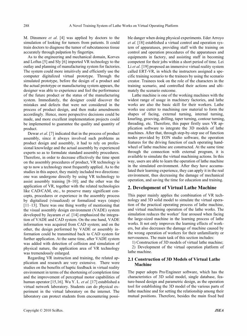
Figure 2. the 3D model required to be constructed still needs to build up the components of transmitting mechanism, such as the axle, variable-speed mechanism, auto-feed mecha-nism, machining feed bench, tool post, power clutch, and tailstock assembly and dead center, etc. As shown in Figure 1.
2) Principles of construction a) Initial condition is carriage clamping lever to be in
sensing status, and transmit its orientation into orientation judgment program;
b) When carriage clamping lever is active (mouse left button or mouse right button be clicked), then carriage clamping lever rotate in CW or CCW direction, and transmit action signal into orientation judgment program;
2.2 Principles for Establishment of Virtual Operation Platform of Lathe Machine
c) To judge whether carriage clamping lever is situated at the position of locked limit by means of orientation judgment program;
To the entire lathe machine, the overall operation func-tions are: 1) Operation for the action of tool change of tool post; 2) Automatic and manual operation for longitudi-nal/transverse feed control; 3) Control of CW and CCW rotation of axle, operation of braking, and simulation of its axle rotation inertia. Here using (1) Operation for the action of tool changes of tool post function as example to explain its construction process.
d) If carriage clamping lever has been at the locked position, it is required to disable the sensing of both the right button of carriage clamping lever and tool post ro-tation;
e) If carriage clamping lever has been deviated from the locked position, it is required to active the sensing of both the right button of carriage clamping lever and tool post rotation.
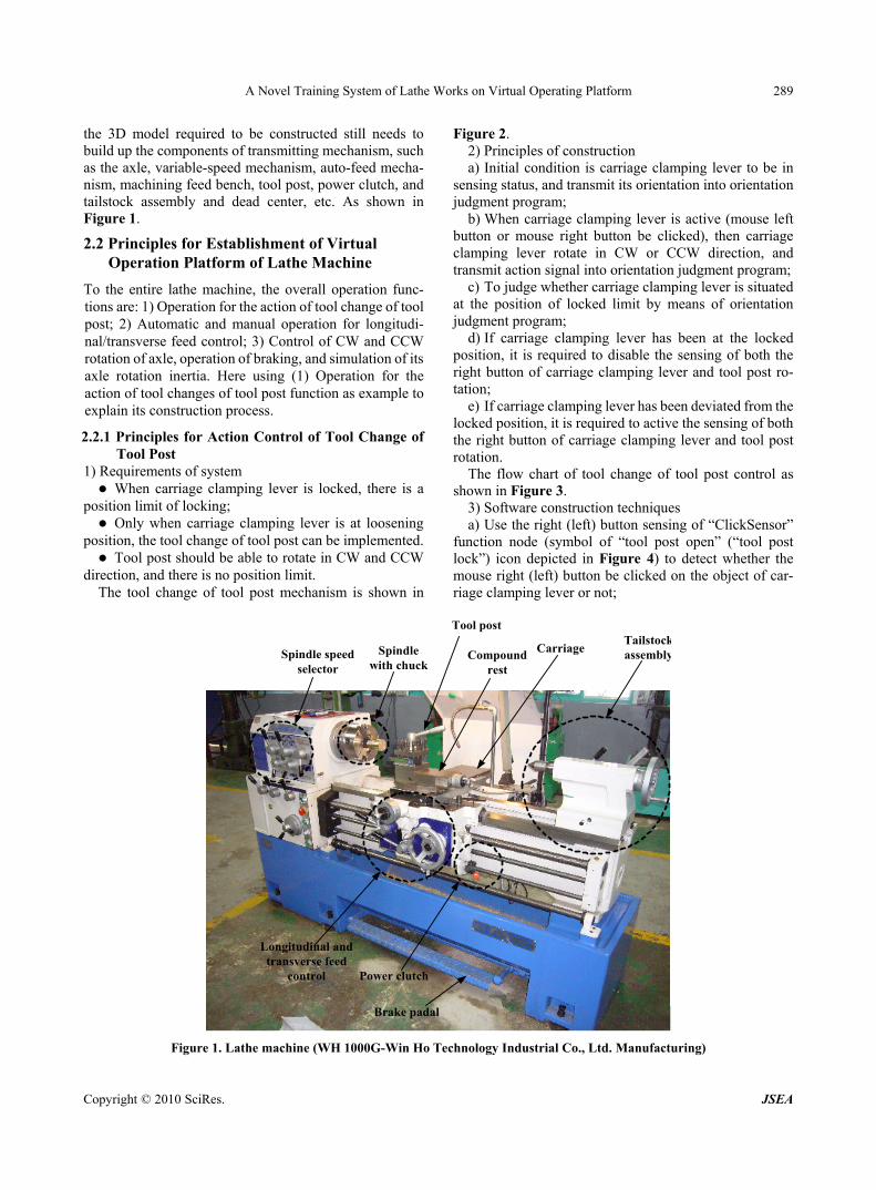
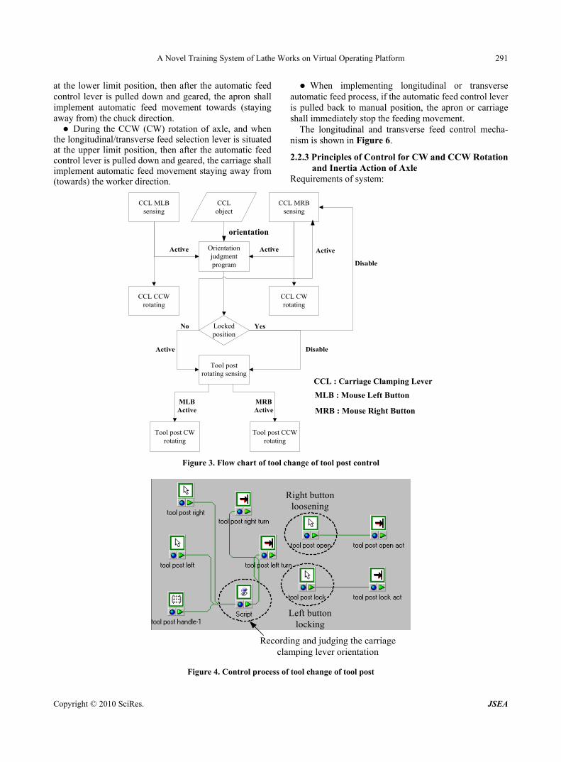
2.2.1 Principles for Action Control of Tool Change of Tool Post
1) Requirements of system The flow chart of tool change of tool post control as shown in Figure 3. When carriage clamping lever is locked, there is a
position limit of locking; 3) Software construction techniques Only when carriage clamping lever is at loosening
position, the tool change of tool post can be implemented. a) Use the right (left) button sensing of “ClickSensor”
function node (symbol of “tool post open” (“tool post lock”) icon depicted in Figure 4) to detect whether the mouse right (left) button be clicked on the object of car-riage clamping lever or not;
Tool post should be able to rotate in CW and CCW direction, and there is no position limit.
The tool change of tool post mechanism is shown in
Longitudinal andtransverse feed
control
Spindle speedselector
Spindlewith chuck
Power clutch
Tool post
CarriageCompound
rest
Tailstockassembly
Brake padal
Figure 1. Lathe machine (WH 1000G-Win Ho Technology Industrial Co., Ltd. Manufacturing)
A Novel Training System of Lathe Works on Virtual Operating Platform 290
b) Use the “Place” function node (symbol of “tool post open act” (“tool post lock act”) icon depicted in Figure 4) to control the object of carriage clamping lever action. i.e. when the mouse right (left) button be clicked on the object of carriage clamping lever, the “ClickSensor” function node will receive the “OnButtonDownTrue” signal, and then it will send out the “SetRun” signal (as the Table 1 listed) to drive the object of carriage clamping lever action;
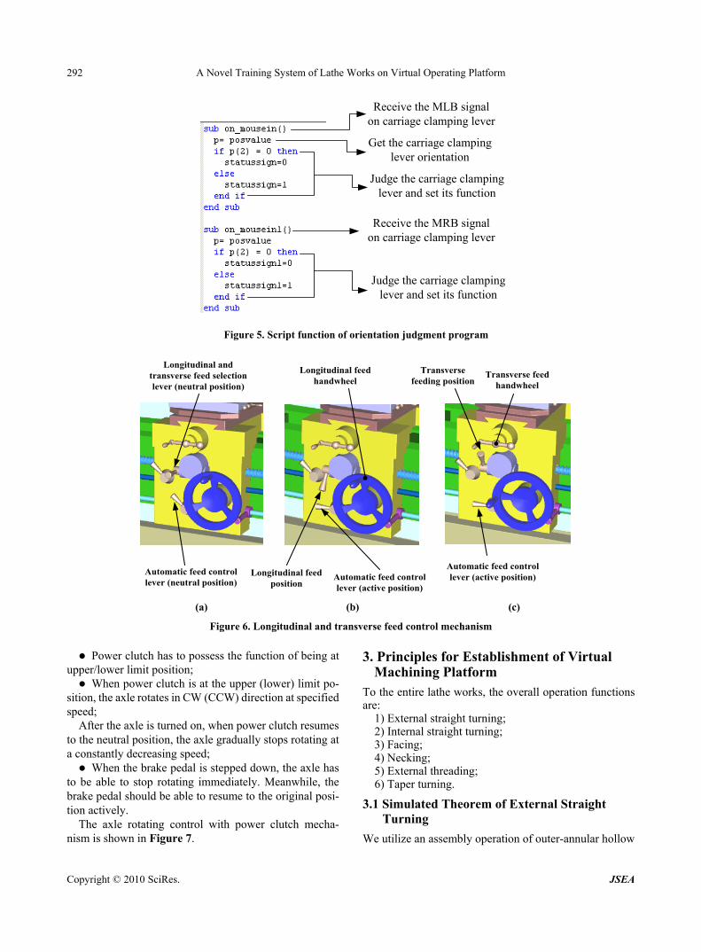
c) Use the “Frame” function node (symbol of “tool post handle-1” icon depicted in Figure 4) to transmit the object of carriage clamping lever’s orientation (“World Orienta-tion” as the Table 1 listed) into orientation judgment program (symbol of “Script” icon depicted in Figure 4);
d) To judge whether carriage clamping lever is situated at the position of locked limit by means of orientation judgment program (as the Figure 5 depicted);
e) If carriage clamping lever has been at the locked position, the orientation judgment program will send out the “statussign” and “statussign1” (as the Table 1 listed) signals to “Place” function node (symbol of “tool post left turn” and “tool post right turn” icons depicted in Figure 4). At this time, the value of “statussign” and “statussign1” signals both are “0”, in other words, it will disable the action of “Place” function node, and then the object of tool
post can not rotate; f) In contrast, if carriage clamping lever has been at the
loosened position, the orientation judgment program will send out the signal value “1” to the “Place” function node, that is say, it will active the “Place” function node, and then the object of tool post can rotate in CW and CCW direction.
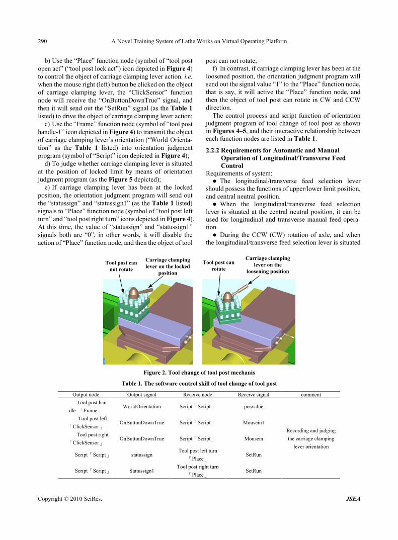
The control process and script function of orientation judgment program of tool change of tool post as shown in Figures 4–5, and their interactive relationship between each function nodes are listed in Table 1.
2.2.2 Requirements for Automatic and Manual Operation of Longitudinal/Transverse Feed Control
Requirements of system: The longitudinal/transverse feed selection lever
should possess the functions of upper/lower limit position, and central neutral position. When the longitudinal/transverse feed selection
lever is situated at the central neutral position, it can be used for longitudinal and transverse manual feed opera-tion. During the CCW (CW) rotation of axle, and when
the longitudinal/transverse feed selection lever is situated
Carriage clampinglever on the locked
position
Tool post cannot rotate
Tool post canrotate
Carriage clampinglever on the
loosening position
Figure 2. Tool change of tool post mechanis
Table 1. The software control skill of tool change of tool post
Output node Output signal Receive node Receive signal comment
Tool post han-
dle 「Frame」 WorldOrientation Script「Script」 posvalue
Tool post left
「ClickSensor」 OnButtonDownTrue Script「Script」 Mousein1
Tool post right
「ClickSensor」 OnButtonDownTrue Script「Script」 Mousein
Script「Script」 statussign Tool post left turn
「Place」 SetRun
Script「Script」 Statussign1 Tool post right turn
「Place」 SetRun
Recording and judging
the carriage clamping
lever orientation
Copyright © 2010 SciRes. JSEA
A Novel Training System of Lathe Works on Virtual Operating Platform 291
at the lower limit position, then after the automatic feed control lever is pulled down and geared, the apron shall implement automatic feed movement towards (staying away from) the chuck direction. During the CCW (CW) rotation of axle, and when
the longitudinal/transverse feed selection lever is situated at the upper limit position, then after the automatic feed control lever is pulled down and geared, the carriage shall implement automatic feed movement staying away from (towards) the worker direction.
When implementing longitudinal or transverse automatic feed process, if the automatic feed control lever is pulled back to manual position, the apron or carriage shall immediately stop the feeding movement.
The longitudinal and transverse feed control mecha-nism is shown in Figure 6.
2.2.3 Principles of Control for CW and CCW Rotation and Inertia Action of Axle
Requirements of system:
CCL MLBsensing
CCL MRBsensing
Orientationjudgmentprogram
CCL CCWrotating
CCL CWrotating
CCLobject
Active Active
orientation
Lockedposition
No Yes
Tool postrotating sensing
Tool post CWrotating
Tool post CCWrotating
Active
MRBActive
MLBActive
Disable
Active
CCL : Carriage Clamping Lever
MLB : Mouse Left Button
MRB : Mouse Right Button
Disable
Figure 3. Flow chart of tool change of tool post control
Right buttonloosening
Left buttonlocking
Recording and judging the carriageclamping lever orientation
Figure 4. Control process of tool change of tool post
Copyright © 2010 SciRes. JSEA
A Novel Training System of Lathe Works on Virtual Operating Platform 292
Receive the MLB signalon carriage clamping lever
Get the carriage clampinglever orientation
Judge the carriage clampinglever and set its function
Receive the MRB signalon carriage clamping lever
Judge the carriage clampinglever and set its function
Figure 5. Script function of orientation judgment program
Longitudinal andtransverse feed selectionlever (neutral position)
Automatic feed controllever (neutral position)
Longitudinal feedposition
Automatic feed controllever (active position)
Longitudinal feedhandwheel
Automatic feed controllever (active position)
Transversefeeding position
Transverse feedhandwheel
(a) (b) (c)
Figure 6. Longitudinal and transverse feed control mechanism
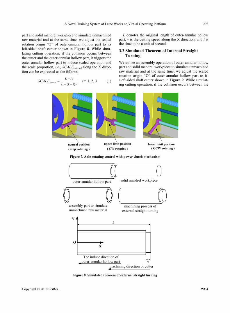
Power clutch has to possess the function of being at
upper/lower limit position; When power clutch is at the upper (lower) limit po-
sition, the axle rotates in CW (CCW) direction at specified speed;
After the axle is turned on, when power clutch resumes to the neutral position, the axle gradually stops rotating at a constantly decreasing speed; When the brake pedal is stepped down, the axle has
to be able to stop rotating immediately. Meanwhile, the brake pedal should be able to resume to the original posi-tion actively.
The axle rotating control with power clutch mecha-nism is shown in Figure 7.
3. Principles for Establishment of Virtual Machining Platform
To the entire lathe works, the overall operation functions are:
1) External straight turning; 2) Internal straight turning; 3) Facing; 4) Necking; 5) External threading; 6) Taper turning.
3.1 Simulated Theorem of External Straight Turning
We utilize an assembly operation of outer-annular hollow
Copyright © 2010 SciRes. JSEA
A Novel Training System of Lathe Works on Virtual Operating Platform 293
part and solid mandrel workpiece to simulate unmachined raw material and at the same time, we adjust the scaled rotation origin “O” of outer-annular hollow part to its left-sided shaft center shown in Figure 8. While simu-lating cutting operation, if the collision occurs between the cutter and the outer-annular hollow part, it triggers the outer-annular hollow part to induce scaled operation and the scale proportion, i.e., SCALEexternal along the X direc-tion can be expressed as the follows.
vtL
tvLSCALEexternal )1(
t = 1, 2, 3 (1)
L denotes the original length of outer-annular hollow part, v is the cutting speed along the X direction, and t is the time to be a unit of second.
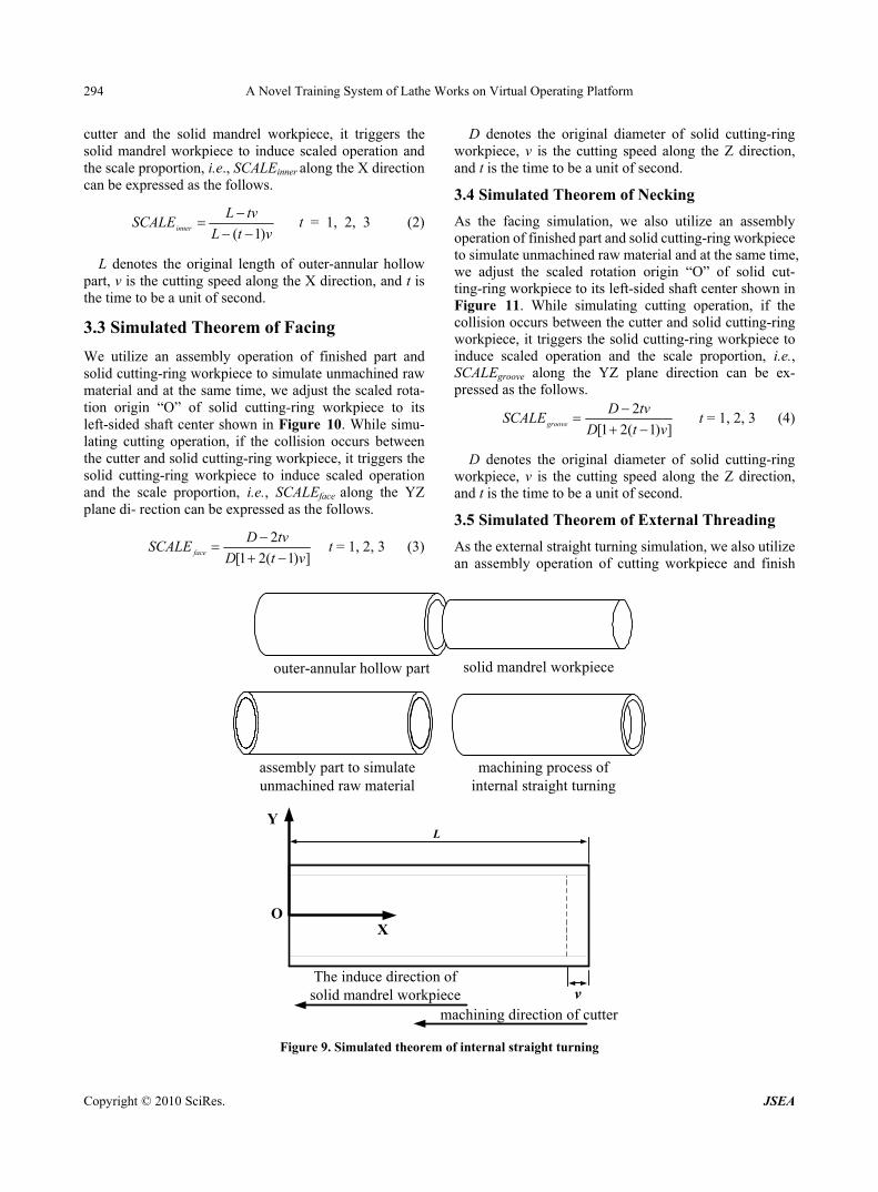
3.2 Simulated Theorem of Internal Straight Turning
We utilize an assembly operation of outer-annular hollow part and solid mandrel workpiece to simulate unmachined raw material and at the same time, we adjust the scaled rotation origin “O” of outer-annular hollow part to it-sleft-sided shaft center shown in Figure 9. While simulat- ing cutting operation, if the collision occurs between the
neutral position upper limit position lower limit position
( stop rotating ) ( CW rotating ) ( CCW rotating )
Figure 7. Axle rotating control with power clutch mechanism
L
v
outer-annular hollow part
X
Y
The induce direction ofouter-annular hollow part
O
solid mandrel workpiece
assembly part to simulateunmachined raw material
machining process ofexternal straight turning
machining direction of cutter
Figure 8. Simulated theorem of external straight turning
Copyright © 2010 SciRes. JSEA
A Novel Training System of Lathe Works on Virtual Operating Platform 294
cutter and the solid mandrel workpiece, it triggers the solid mandrel workpiece to induce scaled operation and the scale proportion, i.e., SCALEinner along the X direction can be expressed as the follows.
vtL
tvLSCALEinner )1(
t = 1, 2, 3 (2)
L denotes the original length of outer-annular hollow part, v is the cutting speed along the X direction, and t is the time to be a unit of second.
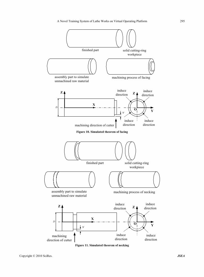
3.3 Simulated Theorem of Facing
We utilize an assembly operation of finished part and solid cutting-ring workpiece to simulate unmachined raw material and at the same time, we adjust the scaled rota-tion origin “O” of solid cutting-ring workpiece to its left-sided shaft center shown in Figure 10. While simu-lating cutting operation, if the collision occurs between the cutter and solid cutting-ring workpiece, it triggers the solid cutting-ring workpiece to induce scaled operation and the scale proportion, i.e., SCALEface along the YZ plane di- rection can be expressed as the follows.
])1(21[
2
vtD
tvDSCALE face
t = 1, 2, 3 (3)
D denotes the original diameter of solid cutting-ring workpiece, v is the cutting speed along the Z direction, and t is the time to be a unit of second.
3.4 Simulated Theorem of Necking
As the facing simulation, we also utilize an assembly operation of finished part and solid cutting-ring workpiece to simulate unmachined raw material and at the same time, we adjust the scaled rotation origin “O” of solid cut-ting-ring workpiece to its left-sided shaft center shown in Figure 11. While simulating cutting operation, if the collision occurs between the cutter and solid cutting-ring workpiece, it triggers the solid cutting-ring workpiece to induce scaled operation and the scale proportion, i.e., SCALEgroove along the YZ plane direction can be ex-pressed as the follows.
])1(21[
2
vtD
tvDSCALEgroove
t = 1, 2, 3 (4)
D denotes the original diameter of solid cutting-ring workpiece, v is the cutting speed along the Z direction, and t is the time to be a unit of second.
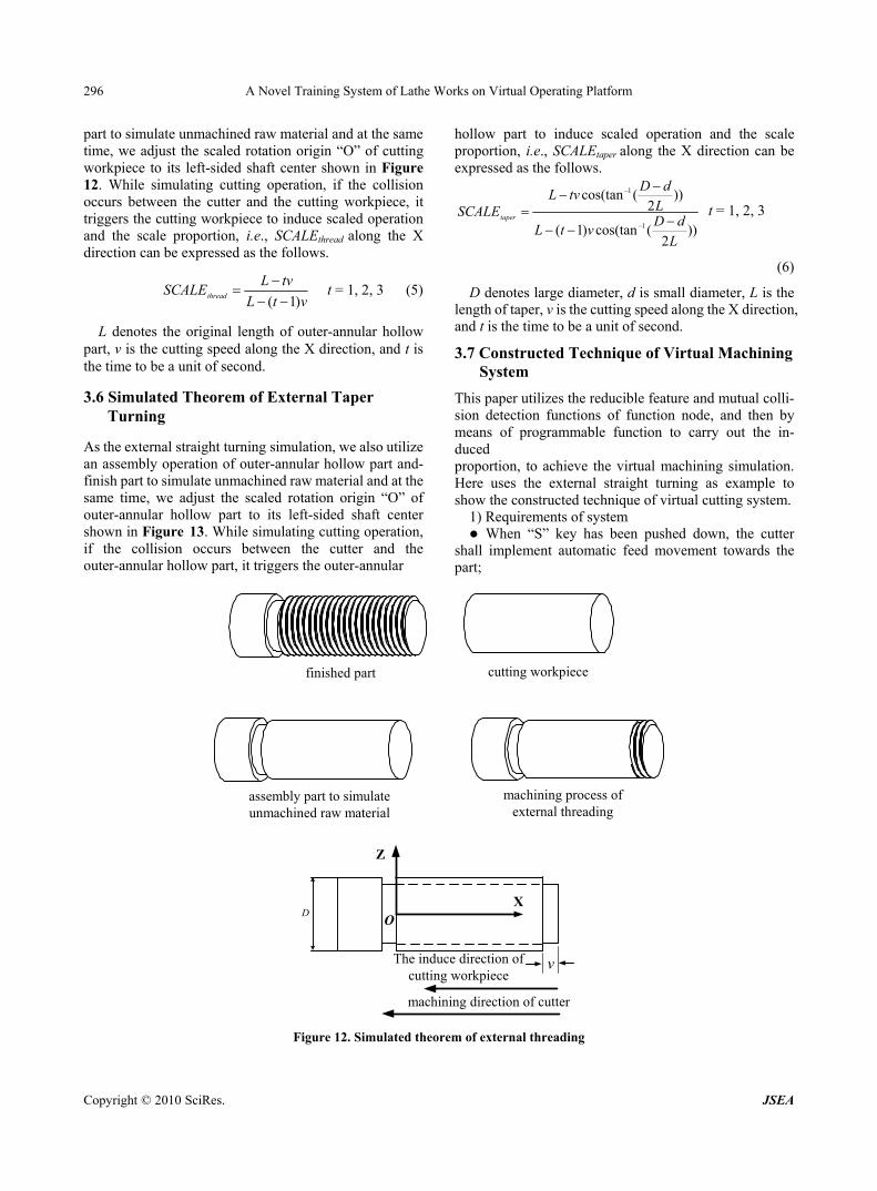
3.5 Simulated Theorem of External Threading
As the external straight turning simulation, we also utilize an assembly operation of cutting workpiece and finish
L
v
outer-annular hollow part
X
Y
O
solid mandrel workpiece
assembly part to simulateunmachined raw material
machining process ofinternal straight turning
The induce direction ofsolid mandrel workpiece
machining direction of cutter
Figure 9. Simulated theorem of internal straight turning
Copyright © 2010 SciRes. JSEA
A Novel Training System of Lathe Works on Virtual Operating Platform 295
finished part
D
v
X
Z Z
YO
solid cutting-ringworkpiece
assembly part to simulateunmachined raw material
machining process of facing
inducedirection
inducedirection
inducedirection
inducedirectionmachining direction of cutter
Figure 10. Simulated theorem of facing
D
v
X
Z Z
YO
finished part solid cutting-ringworkpiece
assembly part to simulateunmachined raw material
machining process of necking
machiningdirection of cutter
inducedirection
inducedirection
inducedirection
inducedirection
Figure 11. Simulated theorem of necking
Copyright © 2010 SciRes. JSEA
A Novel Training System of Lathe Works on Virtual Operating Platform 296
part to simulate unmachined raw material and at the same time, we adjust the scaled rotation origin “O” of cutting workpiece to its left-sided shaft center shown in Figure 12. While simulating cutting operation, if the collision occurs between the cutter and the cutting workpiece, it triggers the cutting workpiece to induce scaled operation and the scale proportion, i.e., SCALEthread along the X direction can be expressed as the follows.
vtL
tvLSCALEthread )1(
t = 1, 2, 3 (5)
L denotes the original length of outer-annular hollow part, v is the cutting speed along the X direction, and t is the time to be a unit of second.
3.6 Simulated Theorem of External Taper Turning
As the external straight turning simulation, we also utilize an assembly operation of outer-annular hollow part and-finish part to simulate unmachined raw material and at the same time, we adjust the scaled rotation origin “O” of outer-annular hollow part to its left-sided shaft center shown in Figure 13. While simulating cutting operation, if the collision occurs between the cutter and the outer-annular hollow part, it triggers the outer-annular
hollow part to induce scaled operation and the scale proportion, i.e., SCALEtaper along the X direction can be expressed as the follows.
))2
(cos(tan)1(
))2
(cos(tan
1
1
L
dDvtL
L
dDtvL
SCALEtaper
t = 1, 2, 3
(6)
D denotes large diameter, d is small diameter, L is the length of taper, v is the cutting speed along the X direction, and t is the time to be a unit of second.
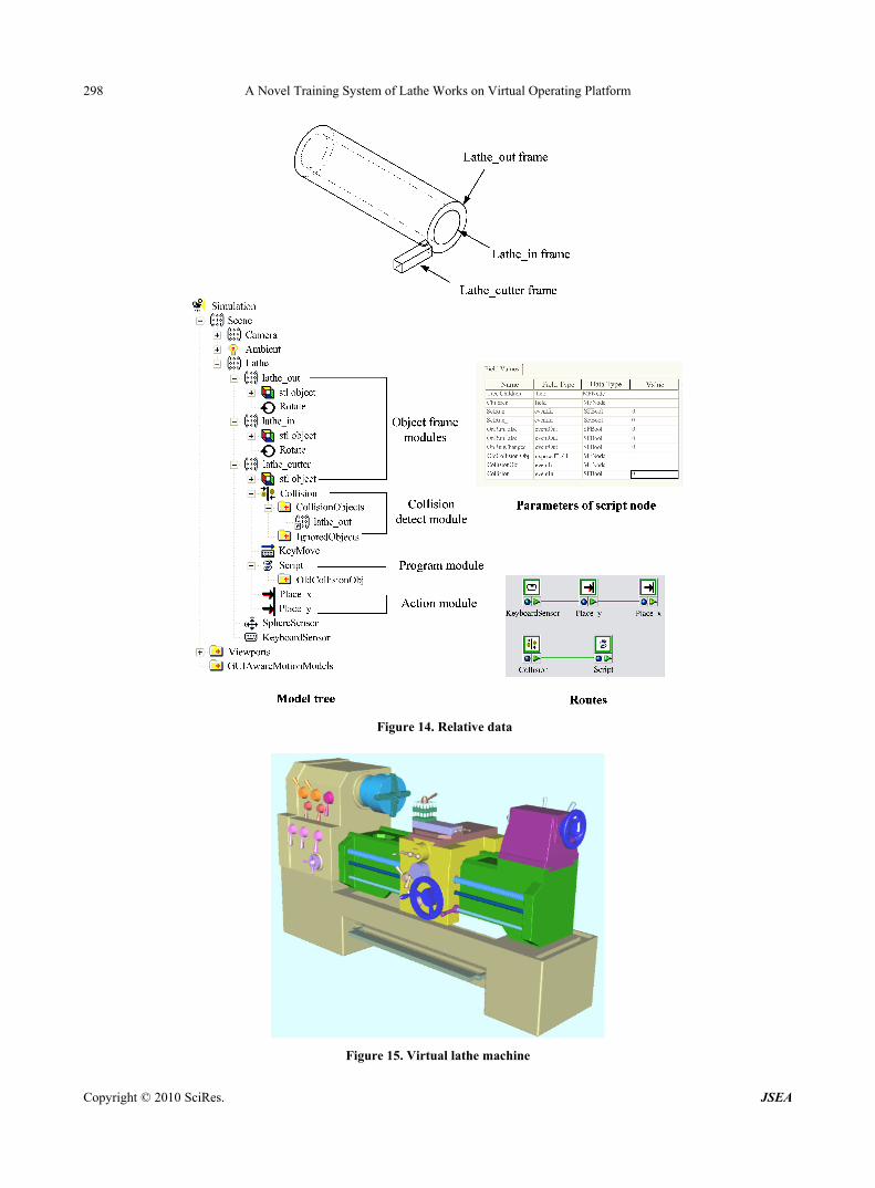
3.7 Constructed Technique of Virtual Machining System
This paper utilizes the reducible feature and mutual colli- sion detection functions of function node, and then by means of programmable function to carry out the in-duced proportion, to achieve the virtual machining simulation. Here uses the external straight turning as example to show the constructed technique of virtual cutting system.
1) Requirements of system When “S” key has been pushed down, the cutter
shall implement automatic feed movement towards the part;
D
v
X
Z
O
finished part cutting workpiece
assembly part to simulateunmachined raw material
machining process ofexternal threading
The induce direction ofcutting workpiece
machining direction of cutter
Figure 12. Simulated theorem of external threading
Copyright © 2010 SciRes. JSEA

A Novel Training System of Lathe Works on Virtual Operating Platform 297
D
v
X
Z Z
Yd
O
d
L
D
finished part outer-annularhollow part
assembly part to simulateunmachined raw material
machining process ofexternal taper turning
The induce directionouter-annular hollow part
machining directionof cutter
Figure 13. Simulated theorem of external taper turning
When the cutter collided with the outer-annular hollow part, the length of outer-annular hollow part must be induced, and the induced speed is the same as cutter moving feed. 2) Constructed technique of software
Use the “ClickSensor” function node to detect the condition that whether “S” key has been pushed down or not;
Use the “Place” function node to control the cutter moving feed.
Use “Script” function node to receive, record, judge and output the induced proportion of length of outer-annular hollow part, so as to control the induced speed is the same as cutter moving feed.
The model tree, routes, and parameters of script node are shown in Figure 14.
4. Practical Operation Cases
This paper makes a comparison between the situations before and after the operating process of the overall transmitting control function and machining function of lathe works, and takes it as an implementation example of virtual lathe machine operating and machining for lathe works.
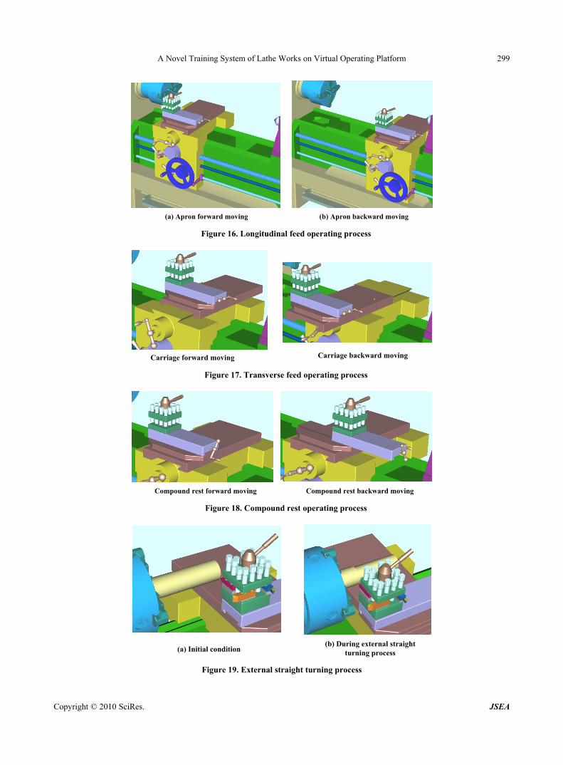
Figure 15 shows the virtual lathe machine platform for this paper. Figure 16 presents the results after the forward and backward movements of apron caused in the longi-
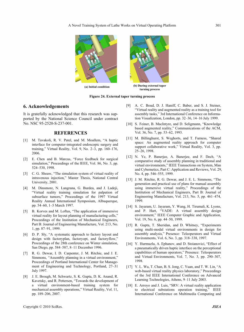
tudinal feed operating process. Figure 17 shows the re-sults after the forward and backward movements of car-riage caused in the transverse feed operating process. Figure 18 shows the results after the forward and back-ward movements of compound rest caused in compound rest operating process. Figure 19 presents the initial and results during external straight turning process. Figure 20 shows the initial and results during internal straight turn-ing process. Figure 21 shows the initial and results during facing process. Figure 22 shows the initial and results during necking process. Figure 23 shows the initial and results during external threading process. Figure 24 shows the initial and results during external taper turning process.
5. Conclusions and Results
The paper integrates virtual reality technology with the application of 3D solid model to complete a virtual op-eration platform based on the transmitting principles of lathe machine during practical operation. At the same time, the paper has completed the virtual machining for various lathe works. Users are able to learn in the simu-lated environment without scruple, increasing the effects of training. After the accumulation of learning experience, it can be applied by users in the actual environment to accomplish the mission of operation.
Copyright © 2010 SciRes. JSEA
A Novel Training System of Lathe Works on Virtual Operating Platform 298
Figure 14. Relative data
Figure 15. Virtual lathe machine
Copyright © 2010 SciRes. JSEA
A Novel Training System of Lathe Works on Virtual Operating Platform 299
(a) Apron forward moving (b) Apron backward moving
Figure 16. Longitudinal feed operating process
Carriage forward moving Carriage backward moving
Figure 17. Transverse feed operating process
Compound rest forward moving Compound rest backward moving
Figure 18. Compound rest operating process
(b) During external straightturning process(a) Initial condition
Figure 19. External straight turning process
Copyright © 2010 SciRes. JSEA

A Novel Training System of Lathe Works on Virtual Operating Platform
Copyright © 2010 SciRes. JSEA
300
(b) During internal straightturning process(a) Initial condition
Figure 20. Internal straight turning process
(a) Initial condition (b) During facing process
Figure 21. Facing process
(a) Initial condition (b) During necking process
Figure 22. Necking process
(a) Initial condition (b) During external threading process
Figure 23. External threading process
A Novel Training System of Lathe Works on Virtual Operating Platform 301
(b) During external taperturning process
(a) Initial condition
Figure 24. External taper turning process
6. Acknowledgements
It is gratefully acknowledged that this research was sup-ported by the National Science Council under contract No. NSC 95-2520-S-237-001.
REFERENCES [1] M. Tavakoli, R. V. Patel, and M. Moallem, “A haptic
interface for computer-integrated endoscopic surgery and training,” Virtual Reality, Vol. 9, No. 2–3, pp. 160–176, 2006.
[2] E. Chen and B. Marcus, “Force feedback for surgical simulation,” Proceedings of the IEEE, Vol. 86, No. 3, pp. 524–530, 1998.
[3] C. G. Shoaw, “The simulation system of virtual reality of intravenous injection,” Master Thesis, National Central University, 2001.
[4] M. Dinsmore, N. Langrana, G. Burdea, and J. Ladeji, “Virtual reality training simulation for palpation of subsurface tumors,” Proceedings of the 1997 Virtual Reality Annual International Symposium, Albuquerque, pp. 54–60, 1–5 March 1997.
[5] B. Korves and M. Loftus, “The application of immersive virtual reality for layout planning of manufacturing cells,” Proceedings of the Institution of Mechanical Engineers, Part B: Journal of Engineering Manufacture, Vol. 213, No. 1, pp. 87–91, 1999.
[6] D. P. Sly, “A systematic approach to factory layout and design with factoryplan, factoryopt, and factoryflow,” Proceedings of the 28th conference on Winter simulation, San Diego, pp. 584–587, 8–11 December 1996.
[7] R. G. Dewar, I. D. Carpenter, J. M. Ritchie, and J. E. Simmons, “Assembly planning in a virtual environment,” Proceedings of Portland International Center for Manage- ment of Engineering and Technology, Portland, 27–31 July 1997.
[8] J. E. Brough, M. Schwartz, S. K. Gupta, D. K. Anand, R. Kavetsky, and R. Pettersen, “Towards the development of a virtual environment-based training system for mechanical assembly operations,” Virtual Reality, Vol. 11, pp. 189–206, 2007.
[9] A. C. Boud, D. J. Haniff, C. Baber, and S. J. Steiner, “Virtual reality and augmented reality as a training tool for assembly tasks,” 3rd International Conference on Informa- tion Visualization, London, pp. 32–36, 14–16 July 1999.
[10] S. Feiner, B. MacIntyre, and D. Seligmann, “Knowledge based augmented reality,” Communications of the ACM, Vol. 36, No. 7, pp. 53–62, 1993.
[11] M. Billinghurst, S. Weghorts, and T. Furness, “Shared space: An augmented reality approach for computer support collaborative work,” Virtual Reality, Vol. 3, pp. 25–26, 1998.
[12] N. Ye, P. Banerjee, A. Banerjee, and F. Dech, “A comparative study of assembly planning in traditional and virtual environments,” IEEE Transactions on System, Man and Cybernetics, Part C: Application and Reviews, Vol. 29, No. 4, pp. 546–555, 1999.
[13] J. M. Ritchie, R. G. Dewar, and J. E. L. Simmons, “The generation and practical use of plans for manual assembly using immersive virtual reality,” Proceedings of the Institution of Mechanical Engineers, Part B: Journal of Engineering Manufacture, Vol. 213, No. 5, pp. 461–474, 1999.
[14] S. Jayaram, U. Jayaram, Y. Wang, H. Tirumali, K. Lyons, and P. Hart, “VADE: A virtual assembly design environment,” IEEE Computer Graphic and Application, Vol. 19, No. 6, pp. 44–50, 1999.
[15] R. Gupta, T. Sheridan, and D. Whitney, “Experiments using multi-modal virtual environments in design for assembly analysis,” Presence: Teleoperators and Virtual Environments, Vol. 6, No. 3, pp. 318–338, 1997.
[16] Y. Hurmuzlu, A. Ephanov, and D. Stoianovici, “Effect of a pneumatically driven haptic interface on the perceptional capabilities of human operators,” Presence: Teleoperators and Virtual Environments, Vol. 7, No. 3, pp. 290–307, 1998.
[17] Y. L. Wu, T. Chan, B. S. Jong, C. Yuan, and T. W. Lin, “A web-based virtual reality physics laboratory,” Proceedings of the 3rd IEEE International Conference on Advanced Learning Technologies, Athens, 9–11 July 2003.
[18] E. Arroyo and J. Luis, “SRV: A virtual reality application to electrical substations operation training,” IEEE International Conference on Multimedia Computing and
Copyright © 2010 SciRes. JSEA

A Novel Training System of Lathe Works on Virtual Operating Platform 302
System, Vol. 1, 7–11 June 1999.
[ 19] L. Li, M. J. Zhang, F. J. Xu, and S. H. Liu, “ERT-VR: An
immersive virtual reality system for emergency rescue training,” Virtual Reality, Vol. 8, pp. 194–197, 2005.
Copyright © 2010 SciRes. JSEA