a novel torsion/bending element for dynamic...
TRANSCRIPT

A novel torsion/bending element for Dynamic Relaxation Modeling
Authors:
Michael R BARNESa, Sigrid ADRIAENSSENS
b, Meghan KRUPKA
b
a Emeritus Professor of Department of Architecture and Civil Engineering,
University of Bath, Bath, BA2 7AY, United Kingdom
bDepartment of Civil and Environmental Engineering,
Princeton University, Princeton, 08544, NJ, United States of America
E-mail: [email protected]
Tel: ++ 1 609 258 4661
Fax: ++ 1609 258 2760
Corresponding author: Sigrid ADRIAENSSENS

Abstract
This paper proposes and validates a three degrees of freedom element formulation that accounts for
torsion and transverse bending of three-dimensional curved elements in explicit numerical analyses
methods such as Dynamic Relaxation. Using finite difference modeling, in-plane distortions and
moments, the increment of twist (and hence torsion) and out-of-plane bending deformations are
determined. Numerical stability and convergence limits of the element are discussed. Two sets of circular
arc test cases validate the accuracy of the element against theoretical and six degrees of freedom finite-
element results. This element is widely applicable and found in strained grid shells and spline stressed
membranes.
Keywords: form-finding, structural analysis, finite difference, dynamic relaxation, bending, torsion
1. Introduction
Early tensile structures, though elegant in shape, were crude in detail as a result of the technology that
was still under development, and also due to a lack of awareness of the importance of the shaping and
supporting elements in the new architecture that was being generated. Systems that shape technical
textiles must be expressive of their function and the materials that they are made of. Ultimately, these
systems which can include compression masts, ring beams and spatially curved systems must be as
refined as the fabric itself. The aesthetics created by the slenderness and delicate equilibrium between
compression, tension and curved elements in systems such as a model for a crane [1] and the more recent
design for a solar shade [2] (see Figure 1a and b) have been a point of reference for this paper. The
physical crane model consists of a central flexible tapering continuous steel member, plexi glass three
pointed stars of diminishing size equi-spaced on the central member, and three sets of nylon cables. A
nylon cable is attached to the end of each star and runs through holes in the underlying stars to a control

mechanism at the foot of the crane. Spatial curves such as three-dimensional S-shapes are achieved by
applying different tension forces to individual cables within one series. The more recent model for a solar
shade design consists of three cantilevering structural spatially curved units. Each unit relies on a
flexible yet strong three-dimensional boundary curved element, twisted and bent into shape by the pre-
stress in the attached flexible membrane.
A desirable aspect in explicit numerical form-finding and load analysis (such as Dynamic Relaxation DR)
for such bending/torsion element-membrane systems (see Figure 1b) is the treatment of the curved
element as a finite difference continuum. Current element formulations that have been developed for DR
to enable form finding and load analysis of non-linear structures are not focused on modeling the
torsion/bending action. Day [3] derived the concept of Dynamic Relaxation as an explicit solution method
for the static behavior of structures from an analogy with tidal flow computations. Equations of damped
structural motion and the constitutive equations of elasticity substituted respectively for the equations of
fluid motion and continuity. Brew and Brotton [4] developed a DR formulation that separated the
equations for equilibrium and compatibility (motion) and did not require the formulation of the overall
stiffness matrix. This vector form of DR has become the most widely used, particularly for highly non-
linear structures, and is adopted in this paper with a kinetic damping approach [5]. This numerical method
has been extensively researched and improved in the works of Barnes [6], Papadrakakis [7], Wakefield
[8], Topping [9] (and more recently Wood [10] and Hand and Lee [11]). For a comprehensive description
of the DR method the reader is referred to Topping [12]. Besides improving the numerical method,
Barnes developed and validated formulations for specific element types such as strut and cable links and
membrane elements that account for cable slackening, membrane buckling and non-linear material
properties. To enable the form-finding and analysis of a wide range of structures, more recent element
developments have included alternative membrane (Gosling and Lewis [13], Hegyi et al. [14]) and
pneumatic elements (Rodriguez et al. [15] ), non regular tensegrity modules (Zhang et al. [16]) (Bel Hadj.
Ali et al. [17]), reciprocal frames links (Douthe and Baverel [18]),pulley elements with friction (Hincz

[19] ) and beam elements (Adriaenssens and Barnes [20]). The novel bending/torsion element presented
in this paper has significant advantages in a DR scheme since it requires only three translational degrees
of freedom per node. Rotational degrees of freedom are not required, and it is often the coupling of these
with axial stiffness and translational degrees of freedom that can cause conditioning problems in explicit
numerical methods.
Figure 1 (a): crane model, a central flexible curve element is shaped by three sets of longitudinal cables
(photo courtesy ILEK,Institut für Leichtbau Entwerfen und Konstruieren) (b) a twisted and bent element
equilibrates with a pre-stressed membrane to form a sun shading structure.(Princeton University student
project photo courtesy S Bagrianski, A Heid and M Krupka)
2. Method
2.1. Dynamic Relaxation Scheme
The basis of the dynamic relaxation method adopted in this paper is to trace step-by-step for small time
increments, t , the motion of each node of a structure until, due to artificial damping, the structure comes
to rest in static equilibrium. In form-finding the process may be started from an arbitrary specification of
geometry, with the motion caused by imposing a stress or force specification in some or all of the

structure components. The form-finding is usually carried out for a weightless state since, after obtaining
an equilibrium state, this allows a subsequent factoring of the pre-stress forces in all components without
affecting the geometry. For load analyses, which must start from the pre-stress equilibrium state, the
motion is caused by suddenly applying the loading. The description of DR summarized briefly below for
skeletal structures with strut and cable links assumes “kinetic” damping of the structural system to obtain
a static equilibrium state [21]. In this procedure the undamped motion of the structure is traced and when
a local peak in the total kinetic energy of the system is detected, all velocity components are set to zero.
The process is then restarted from the current geometry and repeated through further (generally
decreasing) peaks until the energy of all modes of vibration have been dissipated and static equilibrium is
achieved. The dynamic relaxation formulation uses Newton’s second law governing the motion of any
node i in direction x at time t:
t
ixi
t
ix vMR
(1)
Where
t
ixR residual force at node i in direction x at time t, iM lumped mass at node i , set to optimize
convergence and ensure stability of the numerical process [6], t
ixv acceleration at node i in direction x at
time t
Expressing the acceleration term in Eq. (1) in finite difference form and rearranging the equation gives
the recurrence equation for updating the velocity components:
22 tt
ix
t
ix
i
tt
ix vRM
tv
(2)
Hence the updated geometry projected to time 2tt

x x tvi
t t
i
t
ix
t t
/2
(3)
Eqs. (2) and (3) apply for all unconstrained nodes of the mesh in each coordinate direction. These
equations are nodally decoupled in the sense that the updated velocity components are dependent only on
previous velocity and residual force components at a node. They are not directly influenced by the current
2/tt updates at other nodes. Having obtained the complete updated geometry the new link forces can
be determined and resolved together with any the applied load components ixP to give the updated
residuals:
R PF
Lx xix
t t
ix m
t t
j i
t t ( ) ( )
(4)
for all elements m connecting to i,
Where tt
mF force in member m connecting node i to an adjacent node j at time tt ,
tt
mL length of
member m at time tt , calculated using Pythagoras’s theorem in three dimensions.
The procedure is thus time stepped using Eqs. (2)–(4) until a kinetic energy peak is detected. Velocity
components are then reset to zero (with a small adjustment made to the geometry to correct to the true
kinetic energy time peak), and the process is repeated until adequate convergence is achieved.
2.2. Existing In-Plane Bending Element Formulation
To deal with moments and shear forces when initially straight tubular members are deformed (such as the
central core in figure 1a), a spline type formulation can be used as proposed by Adriaenssens and Barnes
[20]. The scheme adopts a finite difference modeling of a continuous beam. Figure 2a represents
consecutive nodes along an initially straight tubular beam traverse, and Figure 2b two adjacent deformed

segments, a and b, viewed normal to the plane of nodes ijk which are assumed to lie on a circular arc of
radius R. The spacing of nodes along the traverse must be sufficiently close to model this, but the segment
lengths need not be equal. The radius of curvature R through ijk and the bending moment M in the arc can
be defined as
sin2
clR and R
EIM
(5)
Where EI is assumed to be constant along the beam, E is modulus of elasticity and I second moment of
area. The free body shear forces ba SS , of elements a an b complying with moment M at j are thus:
ca
all
EIS
.
sin2 and
cb
bll
EIS
.
sin2
(6)
Where cba lll ,, are the distances between nodes ij, jk and ik respectively. The three non-collinear nodes
i,j and k define a two-dimensional surface, referred to in this paper as the plane ijk.
These shear forces aS and bS are applied at nodes i,j and j,k respectively and act normal to the links ij
and jk respectively within the plane ijk. The shear forces act in the direction of the bending moment M at
the middle node j and in the opposite direction at nodes i and k. . The calculations and transformations
required in DR scheme are thus rather simple, with sets of three consecutive nodes being considered
sequentially along the entire transverse, each lying in different planes when modeling a spatially curved
tube bent from an initially straight condition. The formulation is useful for modeling grid shells
employing continuous tubular members, and also for membranes in which flexible battens are employed
to give shape control (as in some sails). The technique can also be extended to deal approximately with
plane circular arcs (either initially strained or unstrained). To deal with the more general case of initially
unstrained and spatially curved tubular members (such as the one depicted in figure 1b) it is necessary to
account additionally for both torsion and transverse (out-of-plane) bending effects.

Figure 2: (a) Consecutive nodes along an initially straight tubular beam traverse; (b) Two adjacent
deformed segments, a and b, viewed normal to the plane ijk.
2.3. Novel Torsion and Transverse Bending Element Formulation
2.3.1. Theory
For initially unstrained spatially curved arcs the local in plane bending can be dealt with in a similar way
as presented in section 2.2,but with the local moments set as 011 RREIM where 0R is the
original radius of curvature and the shear forces (equivalent to equation 6) revised accordingly. The
following theory accounts also for torsion and transverse bending moments in such spatial arc traverses.
In most practical design cases, both deformations (transverse and radial deflections) and moments
(torsional, transverse and radial bending) may be correctly modeled. This is achieved by applying an
artificial “torsional factor” (which is the factor by which the real torsional stiffness GJ must be reduced in
order that transverse deformations may be correctly modeled. G is shear modulus of elasticity and J is the
second polar moment of area). In some other more restrictive cases, for example with arch systems with a
very low span to rise ratio (<150) and/or slenderness ratios which are very high (>500), the transverse
deformations will be incorrectly modeled; however, even in these cases, an important feature which is
still retained is that the transverse bending, radial, and torsional moments can be statically correctly
modeled.
With only three translational degrees of freedom it is possible to determine by finite difference modeling
the in-plane distortions and moments and the increment of twist and hence torsion in each link element of
a spatially curved traverse, but it is not possible to determine directly also the transverse bending
moments from deformations. However, assuming that the lines of action of all forces exerted by
connecting elements (such as cables or membranes) act through the centerline of the curved element (i.e.
with no applied torsion forces due to eccentricity of connections), the transverse moments are always
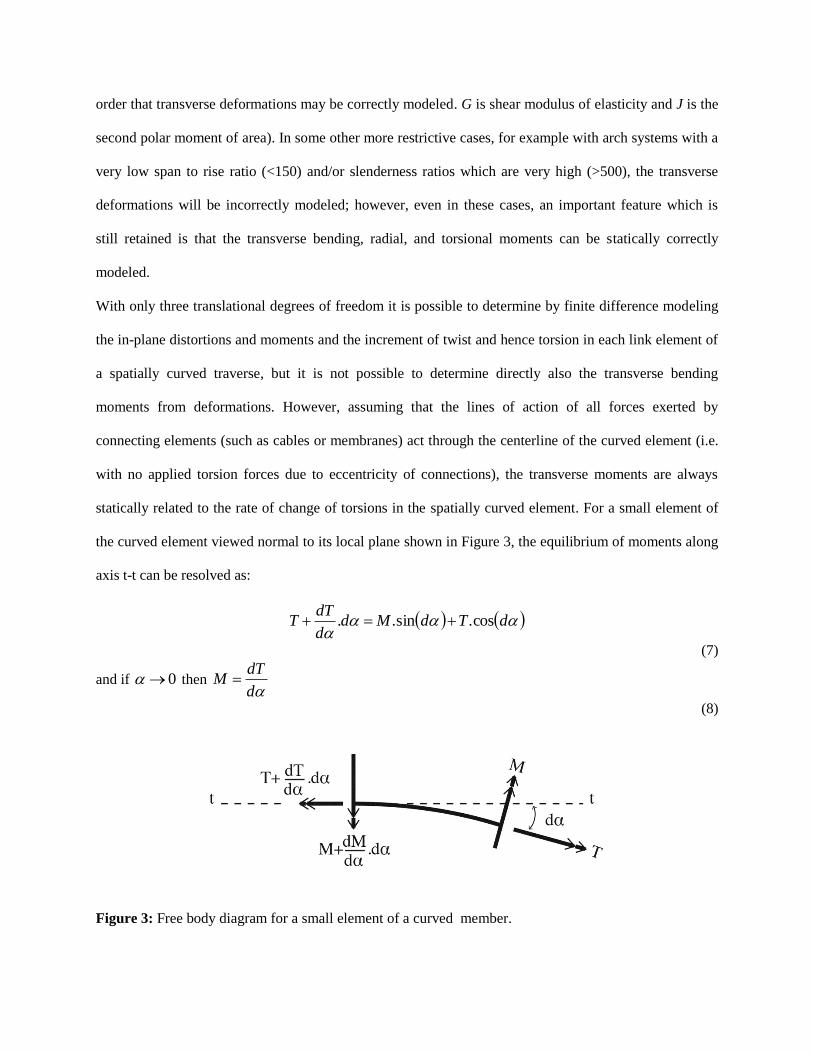
statically related to the rate of change of torsions in the spatially curved element. For a small element of
the curved element viewed normal to its local plane shown in Figure 3, the equilibrium of moments along
axis t-t can be resolved as:
dTdMdd
dTT cos.sin..
(7)
and if 0 then d
dTM
(8)
Figure 3: Free body diagram for a small element of a curved member.

Thus if the torsion in consecutive links and the local (in-plane) curvature is known the transverse (or out-
of-plane) moment at the interconnecting node can be determined from equation 8. The in-plane moment
was determined using two consecutive links. The initial amount of twist i in any link and hence the
torsion can be determined by considering three consecutive links going through the nodes i,j,k and m as
shown in figure 4a and b. More specifically i can be determined from the surface normal kV and lV
at
the nodes k and l of the oriented surfaces, defined by the nodes i,k,l and k,l,m respectively using the right-
hand rule. If the shape of the element then changes (from figure 4b to figure 4c) and the resulting angle of
twist i ', restoring forces mP and jP act at nodes m and j as well as associated forces kP and lP at
nodes k and l due to torsion in link kl. mP acts normal to the oriented surface defined by k,l,m and jP acts
in the opposite direction to the normal of the oriented surface defined by j,k,l result kP acts normal to the
oriented surface defined by j,k,l and jP acts in the opposite direction to the normal of the oriented surface
defined by k,l,m. These associated forces must act to restore the lateral moment equilibrium. jP and mP
are related to the torsion T in link kl with link length klL :
kl
immjj
L
GJThPhP
'
..
(9)
Where jh and mh are the heights of the triangles jkl and klm from the base kl.

Figure 4 : (a) three consecutive links modeling a curved element going through nodes j,k,l and m and
their normal vectors kV and lV
at the nodes k and l of the oriented surfaces, determined by the right-hand
rule and defined by the nodes i,k,l and k,l,m respectively (side view), (b,c) the current twist angle between
them or the initial unstressed state of twist i (view in direction parallel with kl), a change in the
angle of twist results in a new position (d) of the nodes j,k,l and m and sets up restoring forces mP
and jP at nodes m and j due to torsion in link kl result as well as associated forces kP and lP at nodes k
and l to restore the lateral moment equilibrium.
The axis zz, goes acts node k and lies in the bisector plane of the two planes defined by nodes i.k,l and
k,l,m.
Considering static equilibrium of the 3 link configuration (shown in Figure 5) and resolving normal to the
plane containing axis zz, and kl:
jlkmjlkm PPPPPPPP
2cos
2cos
2cos
2cos
''''
(10)
Taking moments about zz gives:
bPcbPaP lmj .).(.
(11)
Where a,b and c are defined in Figure 5. Hence mP and jP can be determined from equation (9), and from
(10) and (11) as:
b
cbPaPP
mj
l
).(. and mjlk PPPP
(12)

Figure 5: Static equilibrium of the three link unit and side view with dimensions.
In the situation of a shallow arc (assuming a consecutive links of similar lengths) the forces kP and lP
are typically three times the values of mP and jP --those latter forces are determined directly in the DR
process from current deformations. However the bending forces exerted by successive sets of three links
along a curved element will tend to oppose and cancel each other, and will do so exactly if the torsions
are constant (equation 8).
For curved elements with inflected sections (as shown in Figure 6), the expressions for mP and jP are
given by equation 9, but the associated bending equilibrium forces are:
baPcbPP jml /).).(( and ljmk PPPP
(13)
In this paper the following sign convention is adhered to: for all cases provided i ' is +ve
(clockwise), jP acts in the - kV direction and opposing kP , and mP acts in the + lV direction and opposing
lP .

Figure 6: Forces acting on a curved element with inflected sections ((a) perspective and (b) view parallel
with kl)
2.3.2. Torsion Factor
During the DR analysis the value of GJ in equation 9 governs the torsional deformations and hence also
the associated transverse bending. In general, for open curved elements the torsional factor may vary
quite widely depending particularly on the radius of curvature of the arch and the total arc length, but also
being limited by the slenderness ratio and the span to rise ratio. Values for torsional factor in the case of
open arches might be assessed by considering a circular arc beam with equal and opposite transverse
loads applied at the quarter points, as shown in Figure 7. The end reactions Q are:
2
)(secPQ
(14)
Where 2
For 0 the transverse moment sinQRM and torsion cos1QRT
For the transverse moment sinsin PRQRM and torsion
)2/)cos1.(sec1(cos. RPT .

The deflection of the ends (at Q) relative to the quarter points (at P) can be derived as two components;
the first associated with transverse bending alone is t
mEI
RPK
2
.. 3
(15a)
Where
2
sinsec K (15b)
And tI is the moment of inertia in the out-of plane direction.
The second component due solely to torsion can be derived as GJ
PRkt
2
. 3
(16a)
Where )5.0(secsin)3cos2sec5.2( k (16b)
In the DR analysis, the total transverse deformations are based only on the twists and torsions related to a
reduced torsion constant, GJT fac , the torsion factor must therefore be set equal to:
KCk
kT
mt
tfac
1
where
tEI
GJC 1 (17)
For the particular case of a circular hollow section with C1=0.8, table 1 gives values of K, k, and facT
corresponding to values of from 2
to
64
.
K k facT Span/Rise
2 0.20181 0.17777 0.524 2.0
4 0.02118 0.00460 0.214 4.83
8 0.00255 0.00014 0.064 10.05
12 0.00075 6100.18 0.029 15.19
16 0.00032 61027.4 0.016 20.31
32 6106.39 61033.1 0.0042 40.71
64 61093.4 61015.4 0.0011 81.47
Table 1: Values for K, k, and facT corresponding to values of from 2
to
64
for a circular hollow
section with C1=0.8
The foregoing value of tEI in equation 17 for bending in the transverse direction (out-of-plane) may be
different to the EI value for bending in the radial direction (in-plane), and thus potentially non-circular
sections such as rectangular hollow sections could be allowed for. All of the above relates to the particular
test cast of transverse loadings at the quarter points of arch beams (with end reaction loads also normal to

the arch), and the values of facT predicted, although independent of loading magnitude, may not be
independent of loading distributions. However, the purpose is to enable the flexibility of arches in the
transverse direction to be approximately modeled so the interactions between a flexible membrane surface
fields and a supporting arch can be accounted for.
Figure 7: A circular arc beam with radius R with equal and opposite transverse loads P at the quarter
points.
2.3.3. Numerical Stability and Convergence
Numerical stability of the DR process is controlled by fictitious mass components used at each node.
These mass components are directly proportional to the stiffness of the elements attached to a node. The
elastic axial stiffness of an element is LEA and the bending stiffness of an arch beam element is
32 LEI . It can be shown that the stiffness of a node due to the coupled torsional and bending effect is
23 )).(.( LRLEIK where R is the in-plane radius of curvature and L is the element length. The value of
K tends to approach 1, and thus generally LR . The coupled torsion/bending stiffness and its
contribution to the nodal mass component will be very much greater than for ordinary in-plane bending.
As a result of these increased mass components, the convergence rate of the DR process is slower for this
type of analysis due to the increased number of iterations. All of the nodal mass components are set
automatically within the numerical process, thus the problem of numerical divergence is not an issue.
However, a type of quasi-stability can occur when the bending stiffness (in-plane or coupled
torsion/transverse bending) are greater than the axial stiffness at any node when the element lengths are
very small. To ensure stable convergence in the case of only axial and bending actions: 32 LEILEA
thus 22 22 rAIL . Hence, for a thin walled tube rL where r is the mid-thickness tube radius. In
the case of coupled torsion/transverse bending it has been found in numerical trials that the least value of
element length is approximately 8).(4 2/1RrrL .
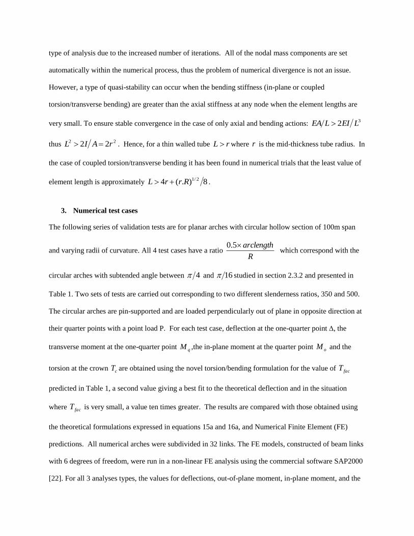
3. Numerical test cases
The following series of validation tests are for planar arches with circular hollow section of 100m span
and varying radii of curvature. All 4 test cases have a ratio R
arclength5.0 which correspond with the
circular arches with subtended angle between 4 and 16 studied in section 2.3.2 and presented in
Table 1. Two sets of tests are carried out corresponding to two different slenderness ratios, 350 and 500.
The circular arches are pin-supported and are loaded perpendicularly out of plane in opposite direction at
their quarter points with a point load P. For each test case, deflection at the one-quarter point ∆, the
transverse moment at the one-quarter point qM ,the in-plane moment at the quarter point oM and the
torsion at the crown cT are obtained using the novel torsion/bending formulation for the value of facT
predicted in Table 1, a second value giving a best fit to the theoretical deflection and in the situation
where facT is very small, a value ten times greater. The results are compared with those obtained using
the theoretical formulations expressed in equations 15a and 16a, and Numerical Finite Element (FE)
predictions. All numerical arches were subdivided in 32 links. The FE models, constructed of beam links
with 6 degrees of freedom, were run in a non-linear FE analysis using the commercial software SAP2000
[22]. For all 3 analyses types, the values for deflections, out-of-plane moment, in-plane moment, and the

center point torsion values are tabulated in Table 2 for slenderness ratio 350 and in Table 3 for
slenderness ratio 500.
Test Series A:
CHS 800mm, t=20mm, span 100m, slenderness ratio L/rg=350, EA= 10 000MN, EI 800MNm2,GJ=640MNm
2
ARC 1A
θ = π/4, R=70.71m,P=100kN
Tfac tm (m) qM (kNm)
oM (kNm) cT (kNm)
Theoretical 0.595 1464 582
Torsion/Bending 0.214 0.530 1455 118 and -161 581
0.191 0.594 1452 132 and -181 580
FE 0.595 1461 135 and -192 582
ARC 2A
θ = π/8, R=130.66,P=100kN
Tfac tm (m) qM (kNm)
oM (kNm) cT (kNm)
Theoretical 0.379 1299 256
Torsion/Bending 0.064 0.323 1282 185 and -138 256
0.055 0.378 1275 219 and -156 256
0.55 0.037 1299 21 and -15 256
FE 0.381 1298 215 and -153 256
ARC 3A
θ = π/12, R=193.19m,P=100kN
Tfac tm (m) qM (kNm)
oM (kNm) cT (kNm)
Theoretical 0.348 1272 167
Torsion/Bending 0.029 0.300 1248 185 and -310 166
0.025 0.344 1240 212 and -358 165
0.25 0.034 1272 24 and -29 167
FE 0.349 1270 210 and -352 167
ARC 4A
θ = π/16, R=256.29m,P=100kN
Tfac tm (m) qM (kNm)
oM (kNm) cT (kNm)
Theoretical 0.342 1262 124
Torsion/Bending 0.016 0.295 1222 240 and -430 123
0.014 0.346 1207 281 and -516 122
0.14 0.034 1262 33 and -38 124
FE 0.342 1261 275 and -511 124
Table 2: Theoretical, Torsion/Bending and FE deflection and moment results for 4 pin-supported
circular arches with slenderness ratio of 350 and of varying heights subjected with opposing out-of plane
100kN point loads at the quarter points.
Test Series B:
CHS 570mm, t=15mm, span 100m, slenderness ratio L/rg=500, EA= 5400MN, EI 220MNm2,GJ=176MNm
2
ARC 1B
θ = π/4, R=70.71m,P=50kN
Tfac tm (m) qM (kNm)
oM (kNm) cT (kNm)
Theoretical 1.082 732 291
Torsion/Bending 0.214 0.967 717 107 and -150 289
FE 1.081 732 124 and -165 291
ARC 2B
θ = π/8, R=130.66,P=50kN
Tfac tm (m) qM (kNm)
oM (kNm) cT (kNm)
Theoretical 0.690 650 128
Torsion/Bending 0.064 0.613 620 171 and -135 128
FE 0.700 648 200 and -144 128
ARC 3B
θ = π/12, R=193.19m,P=50kN
Tfac tm (m) qM (kNm)
oM (kNm) cT (kNm)
Theoretical 0.633 636 83
Torsion/Bending 0.029 0.558 596 167 and -369 81
FE 0.633 637 193 and -475 83
ARC 4B
θ = π/16, R=256.29m,P=50kN
Tfac tm (m) qM (kNm)
oM (kNm) cT (kNm)
Theoretical 0.622 631 62
Torsion/Bending 0.016 - - - -
0.03 0.336 599 180 and -180 64
0.3 0.029 631 15 and -14 62
FE 0.612 634 201 and -198 62
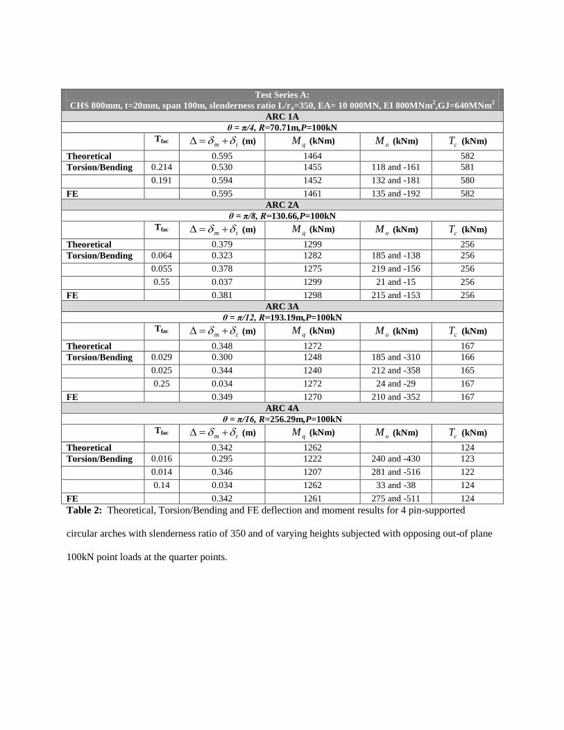
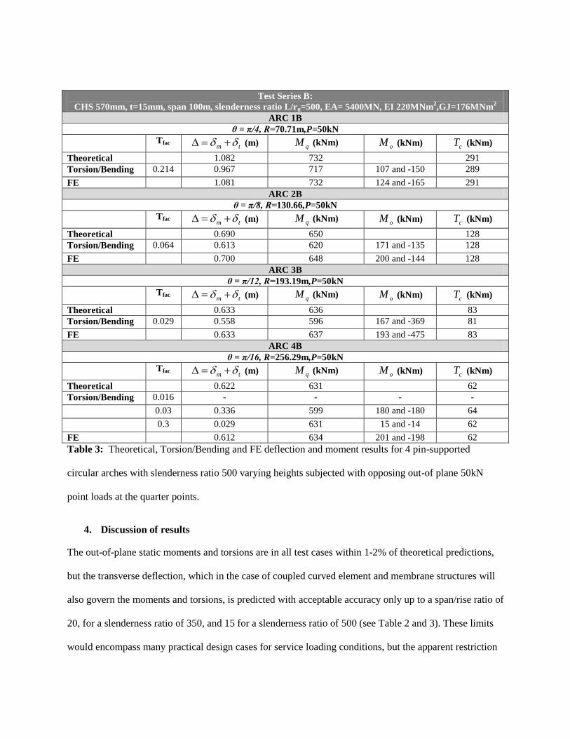
Table 3: Theoretical, Torsion/Bending and FE deflection and moment results for 4 pin-supported
circular arches with slenderness ratio 500 varying heights subjected with opposing out-of plane 50kN
point loads at the quarter points.
4. Discussion of results
The out-of-plane static moments and torsions are in all test cases within 1-2% of theoretical predictions,
but the transverse deflection, which in the case of coupled curved element and membrane structures will
also govern the moments and torsions, is predicted with acceptable accuracy only up to a span/rise ratio of
20, for a slenderness ratio of 350, and 15 for a slenderness ratio of 500 (see Table 2 and 3). These limits
would encompass many practical design cases for service loading conditions, but the apparent restriction

on radii of curvature, especially when using torsion factors (Tfac) which are preferably automatically set in
the analysis program using equations 17 (with equations 15 and 16) must cause difficulties when
attempting ultimate load analyses with arches approaching snap-through buckling. As shown in Test
Series A and B, the shallower an arch becomes, the smaller is the required value of Tfac to give the correct
flexibility, but there is a limit to Tfac below which numerical convergence cannot be obtained. (ARC 4B).
An additional problem in this context is that the effective coupled torsion/transverse bending stiffness is
proportional to 2LR where L is the local element modeling length. An increasing value of R, as well as
making the arch transversely much stiffer as it flattens, will thus also govern the fictitious mass
components which must be used in the DR process to ensure stability and convergence. As snap through
buckling is approached the mass factors will need to be greatly increased and simultaneously the value of
Tfac reduced (with the limit restricted to a least feasible value).
The value of Tfac governs the transverse deformations and consequently also the amount of stretch and
flattening of the arch crown. These phenomena in turn govern the in-plane moments that are induced
(+ve at the ¼ point loading positions and –ve at the crown ). These in-plane moments are also related to
the amount of twist in the arch, which is greatly increased by the reduced torsion constant ( GJT fac ). In
this context the greatest twist at the quarter points in any of the test cases is approximately 10°so it
appears that the arch stretching (and the associated crown flattening) is the dominant effect, which is not
predicted by the analytical model but confirmed by the non-linear FE model.
5. Application
5.1. Tensile membranes and curved active systems
The simplest and most familiar examples of curved active systems supporting a tensile membrane are
slender battens used for pre-stressing umbrellas and igloo camping tents. When an umbrella is opened, a
framework of flexible slender steel battens, stretchers and a runner are deployed against a central pole.
This action stresses the loose rayon on nylon cover. In a typical igloo tent, spatially curved elements made
of strong yet flexible fibre reinforced plastic or aluminum alloy, fit into the tent pockets of a nylon
membrane and are bent into shape and fixed to the ground. In both systems these elements can be very
slender because they are stabilized by the pre-stressed membrane. The presented element type makes the
form finding and load analysis of tensile membrane and curved active systems at a much larger
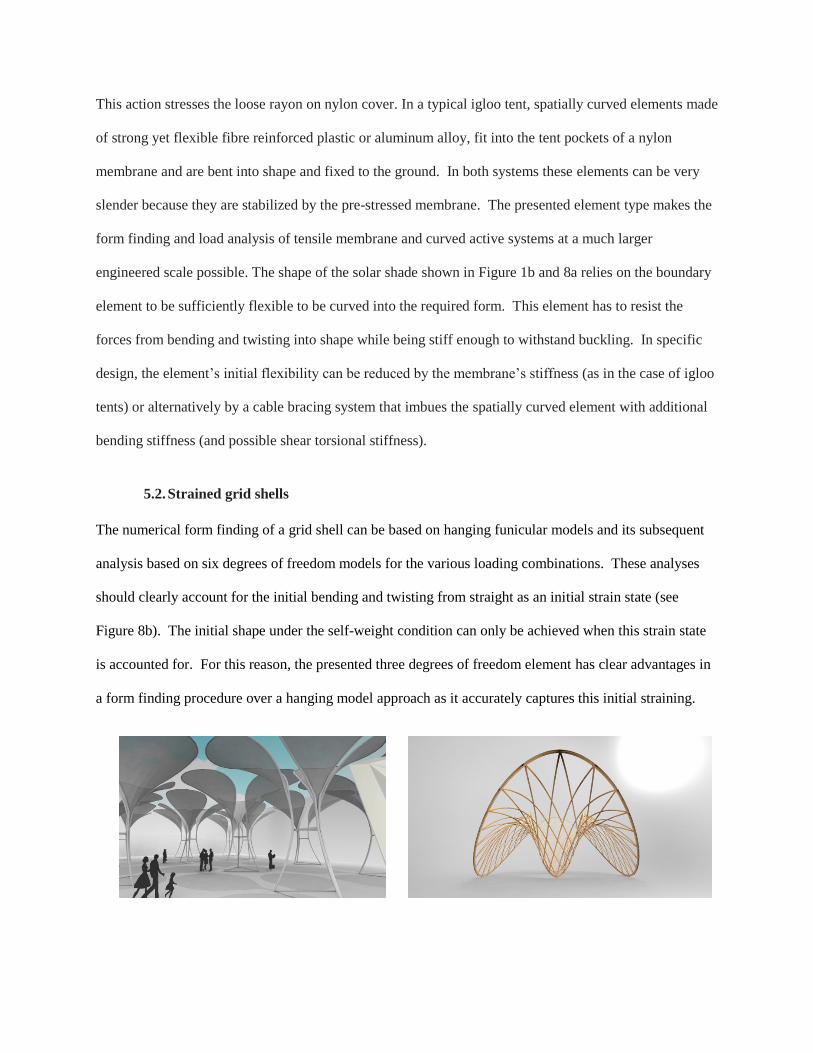
engineered scale possible. The shape of the solar shade shown in Figure 1b and 8a relies on the boundary
element to be sufficiently flexible to be curved into the required form. This element has to resist the
forces from bending and twisting into shape while being stiff enough to withstand buckling. In specific
design, the element’s initial flexibility can be reduced by the membrane’s stiffness (as in the case of igloo
tents) or alternatively by a cable bracing system that imbues the spatially curved element with additional
bending stiffness (and possible shear torsional stiffness).
5.2. Strained grid shells
The numerical form finding of a grid shell can be based on hanging funicular models and its subsequent
analysis based on six degrees of freedom models for the various loading combinations. These analyses
should clearly account for the initial bending and twisting from straight as an initial strain state (see
Figure 8b). The initial shape under the self-weight condition can only be achieved when this strain state
is accounted for. For this reason, the presented three degrees of freedom element has clear advantages in
a form finding procedure over a hanging model approach as it accurately captures this initial straining.

Figure 8: (a) Solar shade that derives its shape from a doubly curved membrane pre-stressed against
a three dimensional curved flexible element (PU student project image courtesy S Bagrianski, A
Heid, M Krupka) (b) The initial shape of a strained grid shell accounts for straining due to bending
and torsion. (SG gridshell image courtesy A Kudless, M Cabrinha and D Shook).
6. Conclusion
This paper presents the theory for a novel bending/torsion element that can be incorporated in explicit
numerical methods such as DR for the form finding of highly non-linear structures. The element
algorithm relies on three translational degrees of freedom only. The coupling of rotational degrees of
freedom with axial stiffness and translational degrees of freedom often causes conditioning problems in
explicit numerical methods (such as DR) and are thus undesirable in any element formulation. The theory
builds on the existing beam element proposed by Adriaenssens and Barnes [20] but extends its scope by
accounting for torsion and out-of-plane bending moments. In the DR analysis, the total transverse
deformations are based only on the twists and torsions related to a reduced torsion constant. The paper
theoretically evaluates this reduction factor or torsional factor for the case of a series of circular arcs with
varying subtended angle, but with equal and opposite transverse loads applied at the quarter points. The
accuracy of the values for deflection at the one-quarter point, the transverse moment at the one-quarter
point, the in-plane moment at the quarter point and the torsion at the crown obtained with the novel
element is then validated against the derived theoretical results and numerical non-linear FE results. The
results for the test cases have demonstrated the stability and convergence of the process within a DR
scheme. The presented element is particularly useful when applied to systems such as grid shells and
complex curved and tension active structures.
.

References
[1] F. Otto, Spannweiten, West Berlin: Verlag Ullstein, 1965.
[2] M. Krupka, "Master thesis: Physical and Numerical Form Finding Techniques for Splines Stressed
Structures," Princeton University, Princeton, 2012.
[3] A. Day, "An introduction to Dynamic Relaxation," The Engineer, vol. 29, pp. 218-221, 1965.
[4] J. Brew and D. Brotton, "Non-linear structural analysis by dynamic relaxation," International
Journal Numerical Methods in Engineering, vol. 3, no. 1, pp. 463-483, 1971.
[5] P. Cundall, "Explicit finite-difference methods in Geo-mechanics," in E F Conference on Numerical
Methods in Geo-Mechanics, Blacksburg, 1976.
[6] M. R. Barnes, "Form-Finding and Analysis of tension space structures by Dynamic Relaxation:
Ph.D. thesis," City University, London, 1977.
[7] E. Papadrakakis, "Gradient and Relaxation non-linear techniques for the analysis of cable supported
structures: Ph.D. thesis," City University, London, 1978.
[8] D. Wakefield, "Dynamic Relaxation Analysis of pre-tensioned networks supported by compression
arches: Ph.D. report," City University, London, 1980.
[9] B. Topping, "The application of Dynamic Relaxation to the Design of Modular Space Structures:
PhD thesis," The City University, London, 1978.
[10] R. Wood, "A simple technique for controlling element distortion in dynamic relaxation form-finding
of tension membranes," Computers and Structures, vol. 80, no. 27-30, pp. 2115-2120, 2002.
[11] S. Han and K. Lee, "A study of the stabilizing process of unstable structures by dynamic relaxation
method," Computers and Structures, vol. 81, no. 17, pp. 1677-1688, 2003.
[12] B. Topping and P. Ivanyi, Computer Aided Design of Cable Membrane Structures, Glasgow: Saxe-
Coburg Publications, 2007.
[13] P. Gosling and W. Lewis, "Optimal structural membranes—II. Form-finding of prestressed
membranes using a curved quadrilateral finite element for surface definition," Computers and
Structures, vol. 61, no. 5, pp. 885-895, 1996.
[14] D. Hegyi, I. Sajtos, G. Geizster and K. Hincz, "Eight-node quadrilateral double-curved surface
element for membrane analysis," Computers and Structures, vol. 84, no. 31-32, pp. 2151-2158,

2006.
[15] J. Rodriguez, G. Rio, J. Cadou and T. J, "Numerical Study of Dynamic Relaxation with kinetic
damping applied to inflatable fabric structures with extensions for 3D solid element and non-linear
behavior," Thin-Walled Structres, vol. 49, no. 11, pp. 1468-1474, 2011.
[16] L. Zhang, B. Maurin and R. Motro, "Form-Finding of Nonregular Tensegrity Systems,"
J.Struct.Eng., vol. 132, pp. 1435-1441, 2006.
[17] N. Bel Hadj Ali, L. Rhode-Barbarigos and I. Smith, "Analysis of clustered tensegrity structures using
a modified dynamic relaxation algorithm," International Journal of Solids and Structures, vol. 48,
no. 5, pp. 637-647, 2011.
[18] C. Douthe and O. Baverel, "Design of nexorades or reciprocal frame systems with the dynamic
relaxation methods," Computers and Structures, vol. 87, no. 21-22, pp. 1296-1307, 2009.
[19] K. Hincz, "Nonlinear analysis of cable net structures suspended with arches with block and tackle
suspension system, taking into account the friction of the pulleys," International Journal of Space
Structures, vol. 24, no. 3, pp. 143-152, 2009.
[20] S. Adriaenssens and M. R. Barnes, "Tensegrity spline beam and grid shell structures," Engineering
Structures, vol. 23, no. 1, pp. 29-36, 2001.
[21] M. Barnes, "Form and stress engineering of tensions structures," Structural Engineering Review, vol.
6, no. 3/4, pp. 175-202, 1994.
[22] "SAP2000 Overview," Computers and Structures Inc., [Online]. Available:
http://www.csiberkeley.com/sap2000. [Accessed 04 06 2012].


Figures
Figure 1 (a) : crane model, a central flexible curve element is shaped by three sets of longitudinal cables
(b) a twisted and bent element equilibrates with a pre-stressed membrane to form a sun shading
structure.(Princeton University student project photo courtesy S Bagrianski, A Heid and M Krupka)
Figure 2: (a) Consecutive nodes along an initially straight tubular beam traverse; (b) Two adjacent
deformed segments, a and b, viewed normal to the plane of nodes ijk.

Figure 3: Free body diagram for a small element of a curved element viewed normal to its local plane
Figure 4 : (a) three consecutive links modeling a curved element going through nodes j,k,l and m and
their current normal direction cosine vectors kV and lV (side view), (b,c) the current twist angle between
them or the initial unstressed state of twist i (view in direction parallel with kl), a change in the
angle of twist results in a new position (d) of the nodes j,k,l and m and sets up restoring forces mP
and jP at nodes m and j due to torsion in link kl result as well as associated forces kP and lP at nodes k
and l to restore the lateral moment equilibrium.
Figure 5: Static equilibrium of the three link unit and side view with dimensions.

Figure 6: Forces acting on a curved element with inflected sections ((a) perspective and (b) view parallel
with kl)
Figure 7: A circular arc beam with radius R with equal and opposite transverse loads P at the quarter
points.
.

Figure 8: (a) Solar shade that derives its shape from a doubly curved membrane pre-stressed against
a three dimensional curved flexible element (PU student project image courtesy S Bagrianski, A
Heid, M Krupka) (b) The initial shape of a strained grid shell accounts for straining due to bending
and torsion. (SG gridshell image courtesy A Kudless, M Cabrinha and D Shook).

Tables
K k facT Span/Rise
2 0.20181 0.17777 0.524 2.0
4 0.02118 0.00460 0.214 4.83
8 0.00255 0.00014 0.064 10.05
12 0.00075 6100.18 0.029 15.19
16 0.00032 61027.4 0.016 20.31
32 6106.39 61033.1 0.0042 40.71
64 61093.4 61015.4 0.0011 81.47
Table 1: Values for K, k, and facT corresponding to values of from
2
to
64
for a circular hollow
section with C1=0.8

Test Series A:
CHS 800mm, t=20mm, span 100m, slenderness ratio L/rg=350, EA= 10 000MN, EI 800MNm2,GJ=640MNm
2
ARC 1A
θ = π/4, R=70.71m,P=100kN
Tfac tm (m) qM (kNm)
oM (kNm) cT (kNm)
Theoretical 0.595 1464 582
Torsion/Bending 0.214 0.530 1455 118 and -161 581
0.191 0.594 1452 132 and -181 580
FE 0.595 1461 135 and -192 582
ARC 2A
θ = π/8, R=130.66,P=100kN
Tfac tm (m) qM (kNm)
oM (kNm) cT (kNm)
Theoretical 0.379 1299 256
Torsion/Bending 0.064 0.323 1282 185 and -138 256
0.055 0.378 1275 219 and -156 256
0.55 0.037 1299 21 and -15 256
FE 0.381 1298 215 and -153 256
ARC 3A
θ = π/12, R=193.19m,P=100kN
Tfac tm (m) qM (kNm)
oM (kNm) cT (kNm)
Theoretical 0.348 1272 167
Torsion/Bending 0.029 0.300 1248 185 and -310 166
0.025 0.344 1240 212 and -358 165
0.25 0.034 1272 24 and -29 167
FE 0.349 1270 210 and -352 167
ARC 4A
θ = π/16, R=256.29m,P=100kN
Tfac tm (m) qM (kNm)
oM (kNm) cT (kNm)
Theoretical 0.342 1262 124
Torsion/Bending 0.016 0.295 1222 240 and -430 123
0.014 0.346 1207 281 and -516 122
0.14 0.034 1262 33 and -38 124
FE 0.342 1261 275 and -511 124
Table 2: Theoretical, Torsion/Bending and FE deflection and moment results for 4 pin-supported
circular arches with slenderness ratio of 350 and of varying heights subjected with opposing out-of plane
100kN point loads at the quarter points.

Test Series B:
CHS 570mm, t=15mm, span 100m, slenderness ratio L/rg=500, EA= 5400MN, EI 220MNm2,GJ=176MNm
2
ARC 1B
θ = π/4, R=70.71m,P=50kN
Tfac tm (m) qM (kNm)
oM (kNm) cT (kNm)
Theoretical 1.082 732 291
Torsion/Bending 0.214 0.967 717 107 and -150 289
FE 1.081 732 124 and -165 291
ARC 2B
θ = π/8, R=130.66,P=50kN
Tfac tm (m) qM (kNm)
oM (kNm) cT (kNm)
Theoretical 0.690 650 128
Torsion/Bending 0.064 0.613 620 171 and -135 128
FE 0.700 648 200 and -144 128
ARC 3B
θ = π/12, R=193.19m,P=50kN
Tfac tm (m) qM (kNm)
oM (kNm) cT (kNm)
Theoretical 0.633 636 83
Torsion/Bending 0.029 0.558 596 167 and -369 81
FE 0.633 637 193 and -475 83
ARC 4B
θ = π/16, R=256.29m,P=50kN
Tfac tm (m) qM (kNm)
oM (kNm) cT (kNm)
Theoretical 0.622 631 62
Torsion/Bending 0.016 - - - -
0.03 0.336 599 180 and -180 64
0.3 0.029 631 15 and -14 62
FE 0.612 634 201 and -198 62
Table 3: Theoretical, Torsion/Bending and FE deflection and moment results for 4 pin-supported
circular arches with slenderness ratio 500 varying heights subjected with opposing out-of plane 50kN
point loads at the quarter points.