a novel reflector/reflectarray antenna - earth science · pdf file ·...
TRANSCRIPT

Scanning Cloud Radar
A Novel Reflector/ReflectarrayAntenna
An Enabling Technology for NASA’s Dual-Frequency ACE Radar
A Novel Reflector/ReflectarrayAntenna
An Enabling Technology for NASA’s Dual-Frequency ACE Radar
Paul E. Racette, Gerald Heymsfield, Lihua LiNASA Goddard Space Flight Center (GSFC)
Michael E. Cooley, Richard Park, Peter StengerNorthrop Grumman Electronic Systems (NGES)
Paul E. Racette, Gerald Heymsfield, Lihua LiNASA Goddard Space Flight Center (GSFC)
Michael E. Cooley, Richard Park, Peter StengerNorthrop Grumman Electronic Systems (NGES)

Overview
• NGES – Goddard Partnership• ACE Mission• Radar Architectures• Proposed Architecture• Ka-band AESA• Dual-freq Reflectarray• Concluding Remarks
Our approach leverages over 15 years of reflectarray antenna technology development

3
GSFC - NGES PartnershipThree Focus Areas
• Technology Implementation– Antennas– Electronics– On-Board Processing– Science Data Processing
• Sensor Definition– Defining architectures to address
science needs
• Sensor Demonstration– Collect data and validate
performance
Dr. Laurie Leshin (former GSFC Director Science & Technology) and Joe Ensor (former VP/GM Space & ISR), Feb. 21st 2008 Signing Space Act Agreement
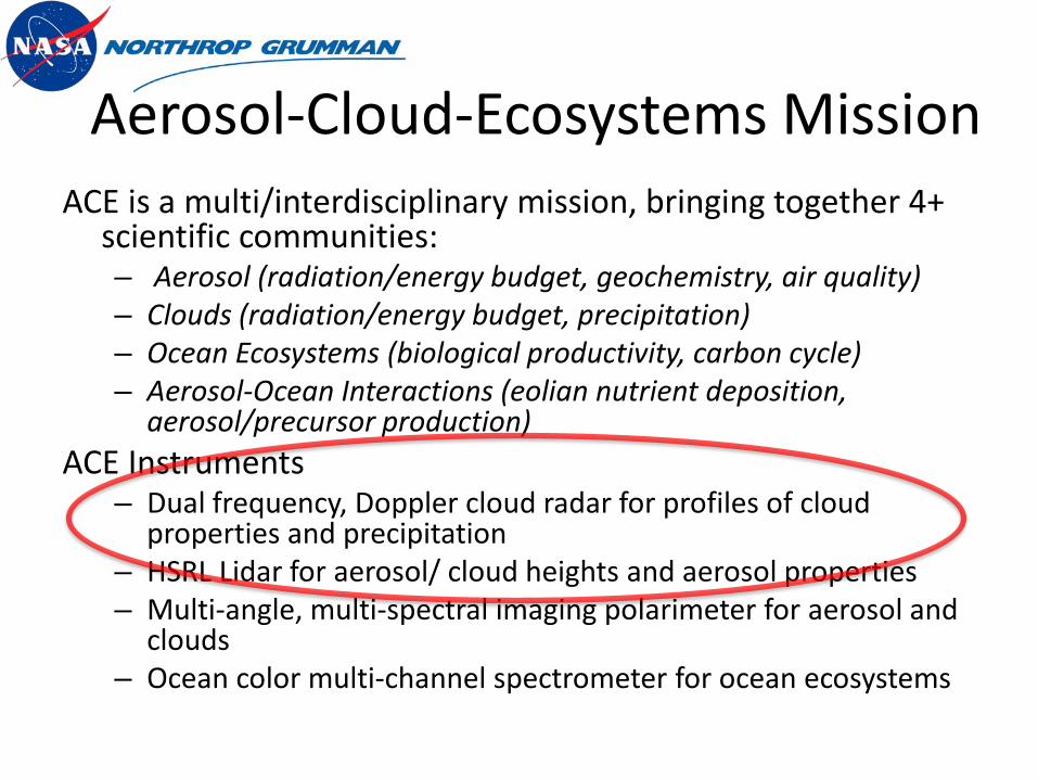
Aerosol-Cloud-Ecosystems MissionACE is a multi/interdisciplinary mission, bringing together 4+
scientific communities:– Aerosol (radiation/energy budget, geochemistry, air quality)– Clouds (radiation/energy budget, precipitation)– Ocean Ecosystems (biological productivity, carbon cycle)– Aerosol-Ocean Interactions (eolian nutrient deposition,
aerosol/precursor production)ACE Instruments
– Dual frequency, Doppler cloud radar for profiles of cloud properties and precipitation
– HSRL Lidar for aerosol/ cloud heights and aerosol properties– Multi-angle, multi-spectral imaging polarimeter for aerosol and
clouds– Ocean color multi-channel spectrometer for ocean ecosystems
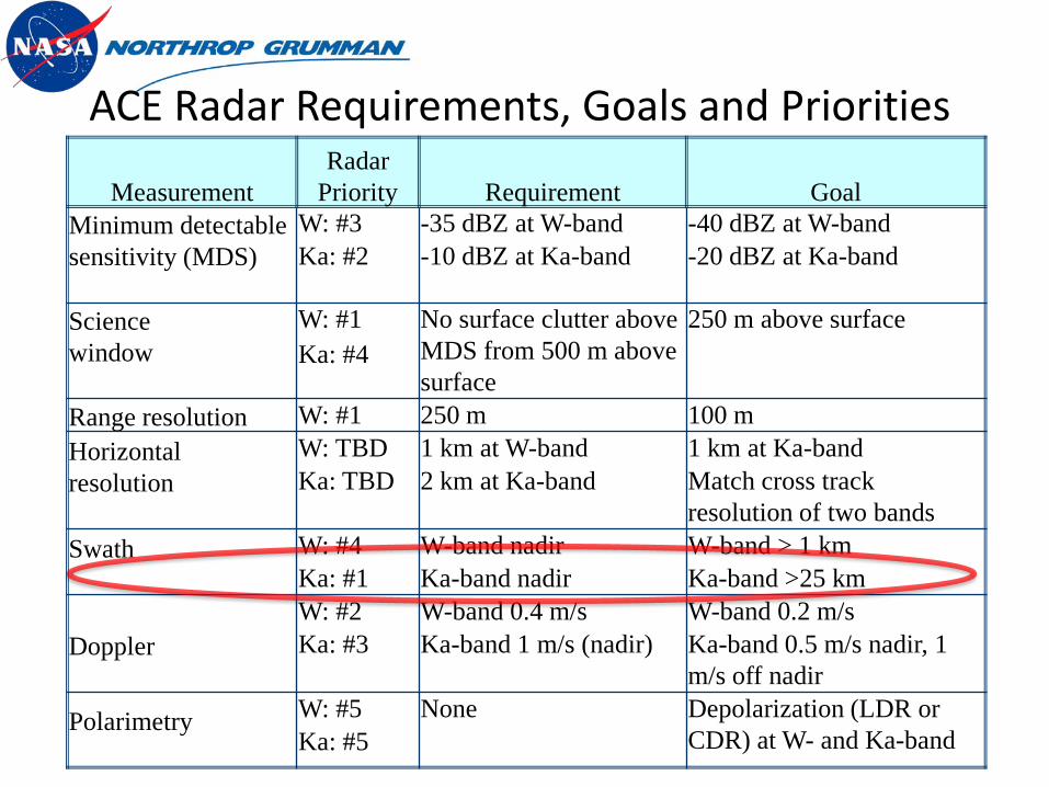
MeasurementRadar
Priority Requirement GoalMinimum detectable sensitivity (MDS)
W: #3 -35 dBZ at W-band -40 dBZ at W-bandKa: #2 -10 dBZ at Ka-band -20 dBZ at Ka-band
Sciencewindow
W: #1 No surface clutter above MDS from 500 m above surface
250 m above surfaceKa: #4
Range resolution W: #1 250 m 100 mHorizontalresolution
W: TBD 1 km at W-band 1 km at Ka-bandKa: TBD 2 km at Ka-band Match cross track
resolution of two bandsSwath W: #4 W-band nadir W-band > 1 km
Ka: #1 Ka-band nadir Ka-band >25 km
DopplerW: #2 W-band 0.4 m/s W-band 0.2 m/sKa: #3 Ka-band 1 m/s (nadir) Ka-band 0.5 m/s nadir, 1
m/s off nadir
Polarimetry W: #5 None Depolarization (LDR or CDR) at W- and Ka-bandKa: #5
ACE Radar Requirements, Goals and Priorities
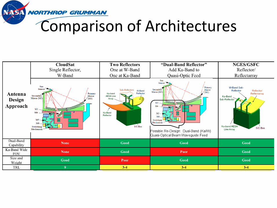
Comparison of Architectures

Dual-Frequency Architecture
SIDE VIEW ISOMETRIC VIEW
W-Band Beam WG (Only 1 Mirror
Shown)
Ka-band AESA Line Array
Ka-Band Sub-Reflector
W-BandSub-Reflector
S/C Bus
Reflector/Reflectarray
Ka-band AESA Line Array
Ka-Band Sub-Reflector
W-Band Sub-Reflector
S/C Bus
Reflector/Reflectarray
Reflector/ReflectarrayFixed W-band, High-TRLW-band FocusingKa-band transparent
Ka-band Active Electronically Scanned AntennaProvides >100 km swathLeverages NGES AESA technologies
System backendLeverages SpaceRadar Designs

Ka-band AESA Module
• Ka-band T/R module is the AESA line feed “building block”• Leverages similar Northrop-Grumman designs from other Programs• Provides azimuth electronic scanning for wide radar FOV• Enables low azimuth sidelobes for high fidelity radar imaging
• Novel GaN T/R model technologies• High performance; low sidelobes, amplitude taper control, calibration, ...• High efficiency, high reliability• Supports tech growth path (multiple beams, wider scanning, etc.)
• Highly integrated multi-site T/R package reduces complexity, cost

Ka-band AESAAdvantage/Benefit Description
Wide Az FOV Enables Imaging * AESA feed provides Az electronic scanningEnhanced Reliability * Distributed nature of AESA feed provides
graceful degradation* Robust design meets effective isotropic radiated power (EIRP) spec with 10% T/R module failure rate
Ultra-Low Az Sidelobes/ Image Fidelity
* AESA feed has amp/phase control* High tolerance reflector surface accuracy* Highly accurate reflectarray surface phasing
Sensor Flexibility, Beamwidth Control * Beam can be broadened in Az via phase spoiling* Provides FOV/coverage flexibility if needed
Calibration/Correction * AESA feed has amp/phase control* Enables calibration/correction for thermal distortion and/or alignment errors
Growth Path –Multiple Az (Rx) Beams * AESA technology enables multiple Az beams* Supports sensor capability spiral growth path for ACE follow-on missions

Novel Dual-Frequency Reflectarray
GSFC pioneered W-band reflectarrays in the 90’s
SIDE VIEW
W-Band Beam WG (Only 1 Mirror
Shown)
Ka-band AESA Line Array
Ka-Band Sub-Reflector
W-BandSub-Reflector
S/C BusKa
L
Reflector/Reflectarr

Scale Model Reflectarray• Design and Fabricate scale model of reflectarray• Electrical characterization at W- and Ka-bands• Environmental testing• Test fly with CRS on ER-2 or WB-57
Scale model of reflectarray will fly with CRS
Cloud Radar System (CRS) is being upgraded with new transceiver and data system

Reflectarray Performance
ParameterKa Gain
(dB)W Gain
(dB) CommentsMaximum directivity (dBi)
64.1 72.7 3m x 5 m aperture
Spillover efficiency (dB)
-0.3 -0.3 Estimate
Taper Efficiency (dB) -1.2 -2 Estimate
Dielectric and Conductor Loss (dB)
-0.1 -0.7 W-band includes element losses
Phase error losses (dB)
-0.3 -0.7 Estimate
Feed losses (dB) -0.5 -0.5 VSWR and line losses
Realized Gain (dBi) 61.7 68.5
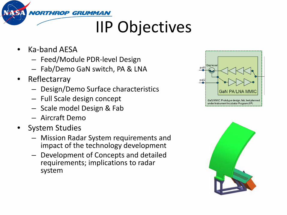
IIP Objectives• Ka-band AESA
– Feed/Module PDR-level Design– Fab/Demo GaN switch, PA & LNA
• Reflectarray– Design/Demo Surface characteristics– Full Scale design concept– Scale model Design & Fab– Aircraft Demo
• System Studies– Mission Radar System requirements and
impact of the technology development– Development of Concepts and detailed
requirements; implications to radar system

Conclusion
• NGES/GSFC has developed novel dual-frequency shared aperture concept for ACE radar
• Dual-frequency reflectarray surface– focusing at W-band
• high-TRL W-band transceiver– transparent at Ka-band
• Ka-band AESA• Three-year IIP to develop/demonstrate key
technologies– PDR level AESA Design– Airborne Demonstration of Reflectarray