a novel method for the vibration optimisation of
TRANSCRIPT

Advances in Aircraft and Spacecraft Science, Vol. 4, No. 2 (2017) 169-184
DOI: http://dx.doi.org/10.12989/aas.2017.4.2.169 169
Copyright © 2017 Techno-Press, Ltd.
http://www.techno-press.org/?journal=aas&subpage=7 ISSN: 2287-528X (Print), 2287-5271 (Online)
A novel method for the vibration optimisation of structures subjected to dynamic loading
David J. Munk, Gareth A. Vio and Grant P. Steven
AMME, The University of Sydney, Bld J11, Sydney, NSW, 2006, Australia
(Received July 29, 2015, Revised December 31, 2015, Accepted January 7, 2016)
Abstract. The optimum design of structures with frequency constraints is of great importance in the aeronautical industry. In order to avoid severe vibration, it is necessary to shift the fundamental frequency of the structure away from the frequency range of the dynamic loading. This paper develops a novel topology optimisation method for optimising the fundamental frequencies of structures. The finite element dynamic eigenvalue problem is solved to derive the sensitivity function used for the optimisation criteria. An alternative material interpolation scheme is developed and applied to the optimisation problem. A novel level-set criteria and updating routine for the weighting factors is presented to determine the optimal topology. The optimisation algorithm is applied to a simple two-dimensional plane stress plate to verify the method. Optimisation for maximising a chosen frequency and maximising the gap between two frequencies are presented. This has the application of stiffness maximisation and flutter suppression. The results of the optimisation algorithm are compared with the state of the art in frequency topology optimisation. Test cases have shown that the algorithm produces similar topologies to the state of the art, verifying that the novel technique is suitable for frequency optimisation.
Keywords: optimisation; topology; flutter; natural frequency; level-set
1. Introduction
Optimal design against vibrations and noise has been undertaken some decades ago in the form
of shape optimisation with respect to the fundamental and higher order eigenfrequencies of
transversely vibrating beams (Olhoff 1976, 1977). Subsequent papers focus on maximisation of
the separation between two consecutive eigenfrequencies of the beam (Olhoff 1984, Bendsoe
1985). A survey by Grandhi (1993) covers the early developments in this area.
Vibration response is a design consideration of a structure subjected to dynamic loads (Bendsoe
2003). For example, it is advantageous to keep the natural frequencies of the structure away from
any driving frequencies that may be applied to the structure. Structures with a high fundamental
frequency result in a stiff design which is good for static loads (Krog 1999). There have been cases
where designers have underestimated the effects of the dynamic response, the most famous
example being the Tacoma Narrows Bridge in 1940, which collapsed due to resonance (von
Karman 2005); the problem being the frequency of the wind's gust differing little from the natural
Corresponding author, Ph.D., E-mail: [email protected]

David J. Munk, Gareth A. Vio and Grant P. Steven
bending and twisting modes of the bridge deck (Blevins 2001). This problem is not confined to
bridge design. Flutter, a dynamic aeroelastic instability, is characterised by the sustained
oscillation of structures arising from the interaction of elastic, inertial and aerodynamic forces
acting on a body (Panda 2009). In aircraft structures the onset of flutter can be a result of the
coalescence of two natural frequencies resulting in zero damping ratio (Bisplinghoff 1962).
Therefore it is advantageous to design the supporting structure such that the natural frequencies are
far enough apart to delay the onset of flutter.
There are several established structural topology optimisation algorithms in the literature. The
first to be applied to frequency optimisation is the homogenization method, developed by Bendsoe
and Kikuchi (1988). This method uses an anisotropic composite with micro-scale voids to
represent the material. For a given case the optimal design is found by optimising these
microstructures and their orientations. Diaz and Kikuchi (1992) were the first to extend the
homogenization method to vibrational optimisation. Subsequently, Ma et al. (1993, 1994, 1995),
Tenek and Hagiwara (1993), Diaz et al. (1994), Krog (1996) analysed the maximisation of
multiple frequencies of freely vibrating disks and plates using the homogenization technique. Krog
and Olhoff (1999) apply a variable bound formulation to facilitate the treatment of multiple
eigenfrequencies.
The first continuous structural topology optimisation technique was developed by Bendsoe
(1989). The Solid Isotropic Material with Penalisation (SIMP) method represents the material
properties by one design variable per element with a penalisation factor. The SIMP method was
extended by Kosaka and Swan (1999) to include optimisation of dynamic problems. However, it
has been demonstrated that the SIMP model is unsuitable for frequency optimisation, as localised
modes tend to appear in low density regions (Pederson 2000). A modified SIMP model using a
discontinuous function has been applied to vibrating continuum structures by Pedersen (2000), Du
and Olhoff (2007), Jensen and Pedersen (2006). Rubio et al. (2011) applied SIMP topology
optimisation for tailoring vibration mode shapes for the design of piezoelectric devices. These
methods are derived from the Karush-Kuhn-Tucker (KKT) optimality conditions (Patel 2008).
A popular non-gradient based optimisation algorithm is the Evolutionary Structural
Optimisation (ESO) method, which uses a physical response function, such as the von Mises
stress, to gradually remove regions of inefficient material (Xie 1993). Xie and Steven (1994) were
the first to extend the ESO method to include frequency optimisation. Xie and Steven (1996)
analysed dynamic problems using the ESO method. Zhao et al. (1995) looked at frequency
optimisation with lumped masses. Zhao et al. (1996) performed optimisation for the natural
frequencies of thin plate bending vibration problems. Yang et al. (1999) applied the hard-kill
BESO method to frequency optimisation problems. More recently Huang et al. (2010) applied the
soft-kill penalty based BESO method to frequency optimisation problems.
A recent structural topology optimisation algorithm, developed by Tong and Lin (2011), called
the Moving Iso-Surface Threshold (MIST) technique is a hybrid of: the ESO method, using a
physics based function, the SIMP method, employs a moving level to define the element based
design variables and the level set method, uses evolving material boundaries expressed as iso-
values or levels. Vasista and Tong (2013) demonstrated this method on pressurised cellular
compliant mechanisms by adding a mixed u/P finite-element formulation alongside the MIST
optimisiation. Vasista and Tong (2014) apply the MIST topology optimisation method to aircraft
structural design and extend the method to three-dimensional „block‟ design.
This article presents a novel method for the topology optimisation of single and multiple
eigenfrequencies of continuum structures. The optimisation method is an extension of the MIST
170

A novel method for the vibration optimisation of structures subjected to dynamic loading
algorithm (Tong 2011) to the eigenvalue problem, with an alternative material interpolation
scheme and level-set method. The objective of the work is to develop an improved optimisation
algorithm for dynamic structures and compare with the current state of the art.
2. Theoretical analysis
This section outlines the optimisation algorithm of the paper. An overview of the MIST
algorithm is given, followed by the structural model. The modifications to the method made for
frequency optimisation is described followed by the convergence criteria.
2.1 Overview of optimisation algorithm
The optimisation problem being solved is one of the form
ul
s
r
tg
tgts
tJ
xxx
x
x
x
0),(
0),(:..
),(:min
The aim is to find the optimum material layout, x values, to minimise the structural objective
function, J, subjected to given finite element, gr, and material, gs, constraints. A physical response
function, Φ, is calculated at all nodal points across the design domain. The physical response
function is determined by the structural objective and gives the relative structural performance of
all points in the domain. An iso-surface, S, intersects the physical response function forming the
contour of the structural boundary (Fig. 1).
Fig. 1 Physical response function for clamped beam
171

David J. Munk, Gareth A. Vio and Grant P. Steven
Weighting factors are applied to the elements to represent the material distribution. Void and
solid elements are modeled by weighting factors of 0 and 1 respectively. In the optimisation update
routine, the elements with all nodal physical response functions above the iso-surface move
towards solid material, and the elements with all nodal physical response functions below the iso-
surface move towards void material. For the elements with nodal physical response functions
above and below the iso-surface, the weighting factor is a function of the projected area above the
iso-surface (Section 2.5.).
2.2 Initialisation of structural model
The structural model must be defined before the optimisation can be started. The structural
model is defined by a finite element mesh. The nodal co-ordinates, element connectivity table,
node numbers connected to each element, and element areas based on the finite element mesh are
stored. The global stiffness, K, and mass, M, matrices are extracted from the finite element solver.
The element stiffness, Ke, and mass, Me, matrices can then be calculated from these.
The problem of eigenvalue maximisation has a trivial solution: in principle an infinite
eigenvalue can be obtained by removing the entire structure (Bendsoe 2003). Therefore a volume
constraint on the amount of material, f, is set. One weighting factor, xi, is used per finite element,
this is similar to the density design variable in the SIMP gradient based method (Bendsoe 1999).
For non-design areas, i.e. areas that are classified as either void or solid due to the design problem,
the weighting factors for these elements are set to either 1 for solid or 0 for void. All the remaining
weighting factors are initialised uniformly with an intermediate value that satisfies the material
constraints. All the weighting factors are stored in vector x. The initial penalisation factor β is set.
The material property model is initialised by defining values for: Esolid, Evoid, ρsolid and ρvoid. The
stabilisation move limit, m, and filter radius are also defined in the initialisation stage.
2.3 Frequency optimisation problem
In finite element analysis the dynamic response of a structure is represented by the following
eigenvalue problem
0)( 2 jnj uMK (1)
where K is the global stiffness matrix, M is the global mass matrix, ωnj is the jth natural frequency
and uj is the eigenvector corresponding to ωnj. The natural frequency and the corresponding
eigenvector are related to each other by the Rayleigh quotient
nj
nj
njm
k2 (2)
where the modal stiffness knj and the modal mass mnj are defined by
j
T
jnj uuk K (3)
j
T
jnj uum M (4)
For the topology optimisation problem of maximising the natural frequency, ωnj, the problem
172
A novel method for the vibration optimisation of structures subjected to dynamic loading
can be stated as (Huang 2010, Xie 1997)
10
0:..
:max
1
*
i
N
i
ii
nj
x
xVVtsE
where Vi is the volume of the ith element and V
* is the predefined total structural volume. The
objective function of the optimisation problem is ωnj. From Eq. (2), the sensitivity of the objective
function can be calculated by
j
i
nj
i
T
jjnj
i
T
j
j
T
jnji
nju
xxuu
x
u
uudx
d MKMK
M
)(2
2
1 (5)
Using the eigenvalue problem (Equation (1)) Equation (5) can be simplified to
j
i
nj
i
T
j
j
T
jnji
nju
xxu
uudx
d MK
M
2
1 (6)
The sensitivity number (Eq. (6)) is an indicator for the change in the eigenvalue, 2
nj , as a result
of the removal of the jth element. It is effectively the gradient of the eigenvalue solution of the
finite element problem. The gradient of each element must be calculated to develop the physical
response function.
2.4 Alternative material interpolation scheme
To obtain the gradient information of the design variable (Section 2.3.), the material properties
must be interpolated between 0, void, and 1, solid material. The most simple material interpolation
scheme is the power law penalisation scheme (Sigmund 1998)
isolidi xExE )( (7)
where β is the penalisation factor, defined in Section 2.2. However, this scheme results in
numerical difficulties for the eigenvalue optimisation problem (Pedersen 2000). The main problem
is that the extremely high ratio between mass and stiffness for small xi and large β (greater than 1)
causes artificial localised vibration modes in the low density regions. A method to avoid this issue
is to keep the ratio between mass and stiffness constant at low xi values by requiring that
solidvoidx )( min (8)
solidvoidEExE )( min (9)
Therefore an alternative material interpolation scheme can be defined as
voidsolidii xx )( (10)
173

David J. Munk, Gareth A. Vio and Grant P. Steven
solidii
void
voidvoidi Exx
E
EExE
)1(1
)( (11)
By differentiating Eqs. (10) and (11) the derivatives of the global mass, M, and stiffness, K,
matrices with respect to the weighting factors can be obtained
isolid
i
Mx
M
(12)
isolidi
void
void
i
KxE
E
x
K 1
1
1
(13)
where isolidM and
isolidK are the ith element mass and stiffness matrices when they are solid. Eqs.
(12) and (13) can be substituted into Eq. (6) to obtain the sensitivity number as a function of the
material interpolation model.
jsolidnjsolidi
void
voidT
j
nji
njuMKx
E
Eu
x ii
21
1
1
2
1
(14)
The sensitivity number for elements tending towards solid and void material can be explicitly
expressed as
jsolid
nj
solid
void
voidvoidT
j
nj
jsolid
nj
solid
void
voidT
j
nj
i
nj
i
uMKE
EEu
uMKE
Eu
dx
d
ii
ii
21
2
12
1
1
1
2
1
1
0
1
i
i
x
x
(15)
This material interpolation scheme is a „soft-kill‟ method, where the elements stiffness and
density are gradually reduced, i.e., elements are not completely removed or included at the end of
the design iteration.
2.5 Alternative method for calculating the level of the iso-surface and updating
weighting factors
To calculate the element weighting factors the iso-surface level, t, must first be calculated using
an iterative bi-section method. In this method the initial value of t is the average of the minimum
and maximum value of the physical response function Φ. The difference between Φ and t is
calculated at all nodes in the design domain. All the weighting factors in the design region are
updated where i is the current element and m, set to 0.1 for the purpose of this study, is a positive
move limit that ensures the overall topology does not change significantly over one design
iteration.
174

A novel method for the vibration optimisation of structures subjected to dynamic loading
Fig. 2 3D view of nodal values of (Φ−tk) for element i
for (Φ−t)<0
otherwisemx
mxifx
i
i
i
1
10 (16)
for (Φ−t)>0
otherwisemx
mxifx
i
i
i
1
1 11 (17)
The amount of material is summed
E
k
N
i ii Ax1
)( where Ai is the area of element i, k is the
current iteration in the bi-section method and NE is the total number of elements in the mesh. The
summed material is then checked against the material constraint, fAtotal (where Atotal is the total
mesh area and f is a volume fraction) and the iso-value, t, is updated
E
k
N
i kk
kk
totalii tt
ttfAAxif
1 )max()1max(
)1min()(
Or
E
k
N
i kk
kk
totalii tt
ttfAAxif
1 )1max(
)min()1min()(
the iso-surface is then calculated by
0
0
02
)min()max(
S
Stt
tkk
k (18)
after each iteration if the sensitivity numbers are all less than zero the iso-surface for the previous
iteration is re-calculated by
175

David J. Munk, Gareth A. Vio and Grant P. Steven
1)min(
)min()max(
2
kk
kk
k ttwherett
t (19)
This process is repeated until the summed material is within a small tolerance, ς, of the material
constraint. For the non-design solid and/or void regions, the value of Φ−tk is set to a positive
number for solid regions and a negative number for void regions.
The updating procedure for elements with either all node values of (Φ−tk)>0 or (Φ−tk)<0 is given
previously, however if (Φ− tk)>0 for some node(s) and (Φ−tk)<0 at other node(s), then
kix is based on the ratio of projected positive area to total element area as seen in Fig. 2.
As can be seen from Fig. 2 the positive area of the element is enclosed in the boundary
outlined by points 1-4. Therefore the weighting factor for the element shown in Fig. 2 is given by
i
iki
A
Ax
k
(20)
To calculate the projected positive area,
ikA the Xv and Yv co-ordinates of the vertex, shown as
points 1 and 2 in Fig. 2, must be determined. This is done by determining the edge of the element
that the vertex lies on, by seeing which edge has one node with a positive (Φ−tk) and one node
with a negative (Φ−tk) value.
Once the correct edge has been identified the co-ordinates of the vertex can be calculated by
calculating the ratio of the positive and negative magnitudes
21
1
kk
k
tt
t
(21)
the co-ordinates of the vertex can be calculated by
)( 121 XXXX v (22)
)( 121 YYYYv (23)
where the values with a subscript of 1 represent the nodes with a positive (Φ−tk) value, and the
values with a subscript of 2 represent the nodes with a negative (Φ−tk) value. Once the co-
ordinates of all the vertices of
ikA are determined, the area,
ikA , is determined by using the
standard method for determining the area of a non-self-intersecting arbitrary polygon using its
vertex co-ordinate data (Zwillinger 2003)
vN
v
vvvvik YXYXA1
11 )(2
1 (24)
where Nv is the number of vertices of
ikA , 1vNX and 1vNY are equal to X1 and Y1 in order to
close the polygon.
176

A novel method for the vibration optimisation of structures subjected to dynamic loading
2.6 Convergence criteria
Standard topology optimisation procedures determine the convergence of the solution when the
change in the element weighting factor is less than a certain percentage, hence
xxx new max (25)
This criterion can be too strict causing the optimiser to run without terminating even though the
overall topology is unchanged. The convergence criteria can be relaxed by considering the change
in the element weighting factor as a function of the area of the total design domain such that
total
N
i
iinew
N
i
i
N
i
iinew
A
Axx
A
Axx
x
E
i
E
E
i
1
1
1 (26)
This criteria (Eq. (26)) is used to determine the convergence of the optimisation algorithm presented in
this article.
2.7 Filtering schemes for solid-void structures
The algorithm presented is a „soft-kill‟ method, hence a material interpolation scheme is required, i.e.
elements are not completely removed. Therefore the final topologies produced are not solid-void
structures. Multiple filtering schemes can be used to transform composite structures into solid-void
topologies. The two methods used here are:
The mean filter
where x is the mean value of the weighting function.
The median filter
where x~ is the median value of the weight function. Initially a mean filter is used, as it does not
favor higher or lower densities. However this may result in elements that are not connected to the
main structure. In this case a median filter is used to remove all outliers.
Filtering schemes can have a large effect on the result of the optimal topology; therefore
sometimes it can be beneficial to use a „hard-kill‟ method, which does not require any filtering to
produce solid-void structures. However, discrete approaches suffer from numerical instabilities
such as: oscillatory solutions and non-converging topologies. This is because discrete approaches
are sensitive to parameter variations (Munk 2015, Sigmund 2013). These issues are particularly
prevalent in dynamic optimization, therefore a „soft-kill‟ algorithm is better suited for this
application. Further, a volume constraint is applied to the topology optimization problem, this
reduces the effect of the filter on the final topology of the structure.
xxif
xxifx
i
i
i1
0 (27)
xxif
xxifx
i
i
i ~1
~0 (28)
177
David J. Munk, Gareth A. Vio and Grant P. Steven
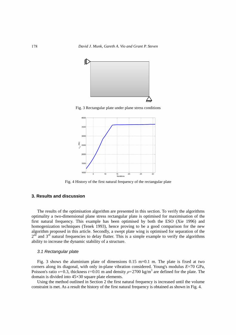
Fig. 3 Rectangular plate under plane stress conditions
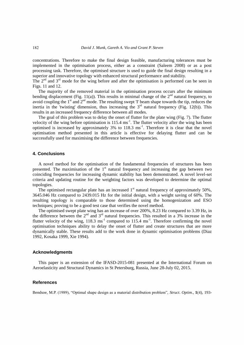
Fig. 4 History of the first natural frequency of the rectangular plate
3. Results and discussion
The results of the optimisation algorithm are presented in this section. To verify the algorithms
optimality a two-dimensional plane stress rectangular plate is optimised for maximisation of the
first natural frequency. This example has been optimised by both the ESO (Xie 1996) and
homogenization techniques (Tenek 1993), hence proving to be a good comparison for the new
algorithm proposed in this article. Secondly, a swept plate wing is optimised for separation of the
2nd
and 3rd
natural frequencies to delay flutter. This is a simple example to verify the algorithms
ability to increase the dynamic stability of a structure.
3.1 Rectangular plate
Fig. 3 shows the aluminium plate of dimensions 0.15 m×0.1 m. The plate is fixed at two
corners along its diagonal, with only in-plane vibration considered. Young's modulus E=70 GPa,
Poisson's ratio ν=0.3, thickness t=0.01 m and density ρ=2700 kg/m3 are defined for the plate. The
domain is divided into 45×30 square plate elements.
Using the method outlined in Section 2 the first natural frequency is increased until the volume
constraint is met. As a result the history of the first natural frequency is obtained as shown in Fig. 4.
178

A novel method for the vibration optimisation of structures subjected to dynamic loading
Fig. 5 A new composite design for the rectangular plate with increased first frequency
Fig. 6 A new solid-void design for the rectangular plate with increased first frequency
After 31 iterations, 60% of the material is removed and the first frequency has been increased
by approximately 50% from 2439.015 Hz to 3645.046 Hz. The corresponding new design is given
in Fig. 5.
Fig. 5 shows the result of the optimisation algorithm for a composite design, i.e., with
intermediate material. For manufacturing purposes a solid-void or 1-0 structure is required.
Therefore the design shown in Fig. 5 can be filtered to produce a 1-0 structure as shown in Fig. 6.
Fig. 6 shows a design which has the same topology as the designs obtained by the
homogenization method (Tenek 1993) and the ESO method (Xie 1996). Since the ESO method
only removes 8 elements at every iteration this method is significantly slower, taking 85 iterations
to remove 50% of the structure compared with 31 for this method. This result gives confidence to
the method for optimisation of maximum frequency. However, there is no control as to what is
happening to the other frequencies during the optimization process. This can lead to other
frequencies dropping below their initial values. Such behaviour is undesirable in structural
mechanics (see Section I). This can be avoided, or at least delayed, by instead of maximising the
first natural frequency, maximise the gap between neighboring frequencies. This method will be
demonstrated in the next section on a wing structure.
3.2 Swept plate wing
Fig. 7 shows the aluminium plate wing of dimensions 0.2 m×0.8 m with a leading edge sweep
angle of Δ=20o. The plate is fixed along one of its edges, to represent a cantilever wing. A Young's
modulus E=70 GPa, Poisson's ratio ν=0.3, thickness t=0.001 m and density ρ=2700 kg/m3 are
defined for the plate. The domain is divided into 20×80 square plate elements.
179

David J. Munk, Gareth A. Vio and Grant P. Steven
Fig. 7 Swept cantilever plate wing
Fig. 8 Convergence plot for the swept plate wing
Fig. 9 A new composite design for the swept plate wing with increased difference between the 2
nd and
3rd
natural frequency
Since the span and chord dimensions must remain consistent the volume constraint for this
optimisation problem is set to 85%. The novel optimisation method of this paper is used to
increase the gap between the 2nd
and 3rd
natural frequencies, as they are the closest before
optimisation. As a result the optimisation history of the difference between the 2nd
and 3rd
natural
frequencies is shown in Fig. 8.
After 55 iterations, 15% of the material is removed and the gap between the 2nd
and 3rd
natural
frequencies has been increased by over 200% from 3.39 Hz to 8.23 Hz. The corresponding new
design, before filtering is performed, can be seen in Fig. 9.
180

A novel method for the vibration optimisation of structures subjected to dynamic loading
Fig. 10 A new solid-void design for the swept plate wing with increased difference between the 2
nd and
3rd
natural frequency
(a) Original model (b) Optimised model
Fig. 11 Second mode shape for the swept wing model
(a) Original model (b) Optimised model
Fig. 12 Third mode shape for the swept wing model
The optimal topology for a composite wing design is given in Fig. 9. For manufacturing
purposes a solid-void structure is required. Therefore the design given in Fig. 9 can be filtered to
produce a solid-void structure as shown in Fig. 10.
Fig. 10 shows an asymmetrical structure that has removed material from the leading and
trailing edges toward the tip. The second natural frequency corresponds to the second bending
mode and the third natural frequency corresponds to the first twisting (torsional) mode. Therefore
the removal of material from either edge is done to increase the frequency of the twisting mode,
while having minimal effect on the second bending mode. The structure starts to build up again as
the tip of the wing is approached (Fig. 10) near the trailing edge, this keeps the frequency of the
second bending mode relatively constant such that it does not approach the first mode. The sweep
angle couples the twisting and bending modes of the wing, causing an asymmetry to appear in the
optimum structure, resulting in more material being removed from the leading edge.
The resulting structure, Fig. 10, differs from conventional wing design. Further, due to the
discrete nature of the finite element mesh, the structure contains sharp edges, which promote stress
181
David J. Munk, Gareth A. Vio and Grant P. Steven
concentrations. Therefore to make the final design feasible, manufacturing tolerances must be
implemented in the optimisation process, either as a constraint (Saleem 2008) or as a post
processing task. Therefore, the optimised structure is used to guide the final design resulting in a
superior and innovative topology with enhanced structural performance and stability.
The 2nd
and 3rd
mode for the wing before and after the optimisation is performed can be seen in
Figs. 11 and 12.
The majority of the removed material in the optimisation process occurs after the minimum
bending displacement (Fig. 11(a)). This results in minimal change of the 2nd
natural frequency, to
avoid coupling the 1st and 2
nd mode. The resulting swept 'I' beam shape towards the tip, reduces the
inertia in the 'twisting' dimension, thus increasing the 3rd
natural frequency (Fig. 12(b)). This
results in an increased frequency difference between all modes.
The goal of this problem was to delay the onset of flutter for the plate wing (Fig. 7). The flutter
velocity of the wing before optimisation is 115.4 ms-1
. The flutter velocity after the wing has been
optimised is increased by approximately 3% to 118.3 ms-1
. Therefore it is clear that the novel
optimisation method presented in this article is effective for delaying flutter and can be
successfully used for maximising the difference between frequencies.
4. Conclusions
A novel method for the optimisation of the fundamental frequencies of structures has been
presented. The maximisation of the 1st natural frequency and increasing the gap between two
coinciding frequencies for increasing dynamic stability has been demonstrated. A novel level-set
criteria and updating routine for the weighting factors was developed to determine the optimal
topologies.
The optimised rectangular plate has an increased 1st natural frequency of approximately 50%,
3645.046 Hz compared to 2439.015 Hz for the initial design, with a weight saving of 60%. The
resulting topology is comparable to those determined using the homogenization and ESO
techniques; proving to be a good test case that verifies the novel method.
The optimised swept plate wing has an increase of over 200%, 8.23 Hz compared to 3.39 Hz, in
the difference between the 2nd
and 3rd
natural frequencies. This resulted in a 3% increase in the
flutter velocity of the wing, 118.3 ms-1
compared to 115.4 ms-1
. Therefore confirming the novel
optimisation techniques ability to delay the onset of flutter and create structures that are more
dynamically stable. These results add to the work done in dynamic optimisation problems (Diaz
1992, Kosaka 1999, Xie 1994).
Acknowledgments
This paper is an extension of the IFASD-2015-081 presented at the International Forum on
Aeroelasticity and Structural Dynamics in St Petersburg, Russia, June 28-July 02, 2015.
References Bendsoe, M.P. (1989), “Optimal shape design as a material distribution problem”, Struct. Optim., 1(4), 193-
182

A novel method for the vibration optimisation of structures subjected to dynamic loading
202.
Bendsoe, M.P. and Kikuchi, N. (1988), “Generating optimal topology in structural design using a
homogenization method”, Comput. Meth. Appl. Mech. Eng., 71(2), 197-224.
Bendsoe, M.P. and Olhoff, N. (1985), “A method of design against vibration resonance of beams and shafts”,
Optim. Control Appl. Meth., 6(3), 191-200.
Bendsoe, M.P. and Sigmund, O. (1999), “Material interpolation schemes in topology optimization”, Arch.
Appl. Mech, 69(9-10), 635-654.
Bendsoe, M.P. and Sigmund, O. (2003), Topology Optimization Theory, Methods and Applications, 1st
Edition, Springer.
Bisplinghoff, R. L. and Ashley, H. (1962), Principles of Aeroelasticity, 1st Edition, Wiley, New York.
Blevins, R.D. (2001), Flow-Induced Vibration, 2nd
Edition, Krieger Publishing Company.
Diaz, A.R. and Kikuchi, N. (1992), “Solutions to shape and topology eigenvalue optimization problems
using a homogenization method”, J. Numer. Meth. Eng., 35, 1487-1502.
Diaz, A.R., Lipton, R. and Soto, C.A. (1994), “A new formulation of the problem of optimum reinforcement
of reissner-midlin plates”, Comput. Meth. Appl. Mech. Eng., 123(1), 121-139.
Du, J. and Olhoff, N. (2007), “Topological design of freely vibrating continuum structures for maximum
values of simple and multiple eigenfrequencies and frequency gaps”, Struct. Multidiscip. Optim., 34(2),
91-110.
Grandhi, R.V. (1993), “Structural optimization with frequency constraints-a review”, AIAA J., 31(12), 2296-
2303.
Huang, X. and Xie, Y.M. (2010), Evolutionary Topology Optimization of Continuum Structures, 1st Edition,
John Wiley and Sons.
Huang, X., Zuo, Z.H. and Xie, Y.M. (2010), “Evolutionary topological optimization of vibrating continuum
structures for natural frequencies”, Eng. Comput., 88(5), 357-364.
Jensen, J.S. and Pedersen, N.L. (2006), “On maximal eigenfrequency separation in two-material structures”,
J. Sound Vib., 289(4), 967-986.
Kosaka, I. and Swan, C.C. (1999), “A symmetry reduction method for continuum structural topology
optimization”, Comput. Struct., 70(1), 47-61.
Krog, L.A. (1996), “Layout optimization of disk, plate, and shell structures”, Technical Report, University of
Denmark.
Krog, L.A. and Olhoff, N. (1999), “Optimum topology and reinforcement design of disk and plate structures
with multiple stiffness and eigenfrequency objectives”, Comput. Struct., 72(4), 535-563.
Ma, Z.D., Cheng, H.C. and Kikuchi, N. (1994), “Structural design for obtaining desired eigenfrequencies by
using the topology and shape optimization method”, Comput. Syst. Eng., 5(1), 77-89.
Ma, Z.D., Kikuchi, N. and Cheng, H.C. (1995), “Topological design for vibrating structures”, Comput. Meth.
Appl. Mech. Eng., 121(1), 259-280.
Ma, Z.D., Kikuchi, N., Cheng, H.C. and Hagiwara, I. (1993), “Topology and shape optimization methods for
structural dynamic problems”, Optim. Des. Adv. Mater., Elsevier Science Publishers, Amsterdam, 247-
261.
Munk, D.J., Vio, G.A. and Steven, G.P. (2015), “Topology and shape optimization methods using
evolutionary algorithms: a review”, Struct. Multidisc. Optim., 52(3), 613-631.
Olhoff, N. (1976), “Optimization of vibrating beams with respect to higher order natural frequencies”, J.
Struct. Mech., 4(1), 87-122.
Olhoff, N. (1977), “Maximizing higher order eigenfrequencies of beams with constraints on the design
geometry”, J. Struct. Mech., 5(2), 107-134.
Olhoff, N. and Parbery, R. (1984), “Designing vibrating beams and rotating shafts for maximum difference
between adjacent natural frequencies”, J. Solid. Struct., 20(1), 63-75.
Panda, C. and Venkatasubramani, S.R.P. (2009), “Aeroelasticity-in general and flutter phenomenon”,
Proceedings of the Second International Conference on Emerging Trends in Engineering and Technology,
ICETET-09.
Patel, N.M., Tillotson, D., Renaud, J.E., Tover, A. and Izui, K. (2008), “Comparative study of topology
183

David J. Munk, Gareth A. Vio and Grant P. Steven
optimization techniques”, AIAA J., 46(8), 1963-1975.
Pedersen, N.L. (2000), “Maximization of eigenvalues using topology optimization”, Struct. Multidisc.
Optim., 20(1), 2-11.
Rubio, W.M., Paulino, G.H. and Silva, E.C.M. (2011), “Tailoring vibration mode shapes using topology
optimization and functionally graded material concepts”, Smart Mater. Struct., 20(2), 025009.
Saleem, W., Yuqing, F. and Yunqiao, W. (2008), “Application of topology optimization and manufacturing
simulations-a new trend in design of aircraft components”, Proceedings of the International Multi
Conference of Engineers and Computer Scientists, Vol. II, IMECS, Hong Kong.
Sigmund, O. and Maute, K. (2013), “Topology optimization approaches-a comparative review”, Struct.
Multidisc. Optim., 48(6), 1031-1055.
Sigmund, O. and Petersson, J. (1998), “Numerical instabilities in topology optimization: A survey on
procedures dealing with checkerboards, mesh-dependencies and local minima”, Struct. Optim., 16(1), 68-
75.
Tenek, L.H. and Hagiwara, I. (1993), “Static and vibrational shape and topology optimization using
homogenization and mathematical programming”, Comput. Meth. Appl. Mech. Eng., 109(1), 143-154.
Tong, L. and Lin, J. (2011), “Structural topology optimisation with implicit design variable optimality and
algorithm”, Finite Elem. Anal. Des., 47(8), 922-932.
Vasista, S. and Tong, L. (2013), “Topology-optimized design and testing of a pressure-driven morphing-
aerofoil trailing-edge structure”, AIAA J., 51(8), 1898-1907.
Vasista, S. and Tong, L. (2014), “Topology optimisation via the moving iso-surface threshold method:
Implementation and application”, Aeronautic. J., 118(1201), 315-342.
Von Karman, T. (2005), “Collapse of the Tacoma narrows bridge”, Reson., 10(8), 97-102.
Xie, Y.M. and Steven, G.P. (1993), “A simple evolutionary procedure for structural optimization”, Comput.
Struct., 49(5), 885-896.
Xie, Y.M. and Steven, G.P. (1994), “A simple approach to structural frequency optimization”, Comput.
Struct., 53(6), 1487-1491.
Xie, Y.M. and Steven, G.P. (1996), “Evolutionary structural optimization for dynamic problems”, Comput.
Struct., 58(6), 1067-1073.
Xie, Y.M. and Steven, G.P. (1997), Evolutionary Structural Optimization, 1st Edition, Springer.
Yang, X.Y., Xie, Y.M., Steven, G.P. and Querin, O.M. (1999), “Topology optimization for frequencies using
an evolutionary method”, J. Struct. Eng., 125(12), 1432-1438.
Zhao, C., Steven, G.P. and Xie, Y.M. (1995), “Evolutionary natural frequency optimization of two
dimensional structures with nonstructural lumped masses”, Technical Report, Finite Element Analysis
Research Centre, The University of Sydney.
Zhao, C., Steven, G.P. and Xie, Y.M. (1996), “Evolutionary natural frequency optimization of thin plate
bending vibration problems”, Struct. Optim., 11(3-4), 244-251.
Zwillinger, D. (2003), CRC Standard Mathematical Tables and Formulae, Chapman and Hall/CRC Press:
Boca Raton, FL, U.S.A.
184