a novel approach for dynamics compen- sation in boiler ... · a novel approach for dynamics...
TRANSCRIPT

387Closed Loop Control of Soft Switched Forward Converter Using Intelligent Controller
IJCTA, 10(02), 2017, pp. 387-398© International Science Press
A Novel Approach for Dynamics Compen-sation in Boiler Drum Level ControlM. Saravanabalaji* E. Muthuramalingam* V. Athappan* and D. Arunnehru**
Abstract : The boiler drum level control is one of a critical control in a power generation plant because the fl uctuation in the water level will leads to uneconomical situation .In generally large power generation plant has three element control scheme is used for boiler drum level control. Three element control scheme is one of the most control methodology used in a high pressure boilers. In this conventional scheme the boiler drum oscillations, power loss are occurred also the high pressure of water to spoil the control valve life time. This are all the dynamics occurred during the boiler operation it will lead to affect the steam production and boiler performance also affects the overall plant performance. To overcome the drawbacks of existing method of control scheme the implementation of feed water fl ow pressure compensation method is used to which control the water level in boiler drum and overcome the dynamics. Like power loss is reduced, increase the control valve life time and reduced water fl uctuation in the drum. The VFD control is used to achieve the feed water fl ow pressure compensation. VFD will receive the control signal from PID4 based on the signal the frequency variation will lead to drive the pump. Since the feed water pump is controlled using VFD and the pressure is also compensated and level is maintained properly and fl uctuation is also reduced. This project work was implemented a 32MW cogeneration thermal plant with the help of yokogawa DCS.Keyword : Boiler drum, level, fl ow, steam, feed water, shrinkage, dynamics, swelling.
1. INTRODUCTION
In thermal Power Station fuel burns & uses the resultant to make the steam, which derives the turbo generator. The Fuel coal is burnt in pulverized from. The pressure energy of the steam produce is converted into mechanical energy with the help of turbine. The mechanical energy is fed to the generator where the magnet rotate inside a set of stator winding & thus electricity is produced in India 65% of total power is generation by thermal power stations.
2. COGENERATION PLANT
This control scheme is implanting a cogeneration plant with a capacity of 25 MW power generations. The plant is operational with Multi Fuel High Pressure Boilers and Turbines.
3. BOILER
Boiler is defi ned as a closed vessel in which steam is produced from water by the combustion of fuel. Generally, in boilers steam is produced by the interaction of hot fl ue gases with water pipes which is coming out from the fuel mainly coal or coke. In boilers, chemical energy of stored fuel is converted into the heat energy and this heat energy is absorbed by the water which converts them into a steam. Boilers have many serious injuries and destruction of property. It is critical for the safe operation of the boiler and * Assistant professor, Department of Electronics and instrumentation Engineering, Kumaraguru college of Technology, Coimbatore
E-mail: [email protected], [email protected], [email protected]** Assistant professor, Department of Electrical and Electronics Engineering, Indus Engineering college, Coimbatore E-mail :
388 M. Saravanabalaji, E. Muthuramalingam, V. Athappan and D. Arunnehru
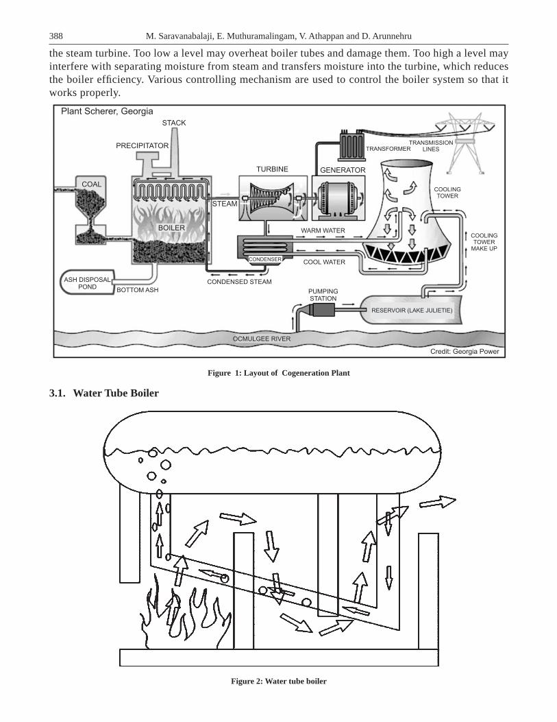
the steam turbine. Too low a level may overheat boiler tubes and damage them. Too high a level may interfere with separating moisture from steam and transfers moisture into the turbine, which reduces the boiler effi ciency. Various controlling mechanism are used to control the boiler system so that it works properly.
STACK
PRECIPITATOR
Plant Scherer, Georgia
TURBINE
COAL
BOILER
STEAM
ASH DISPOSALPOND
BOTTOM ASH
CONDENSED STEAM
OCMULGEE RIVER
PUMPINGSTATION
COOL WATERCONDENSER
WARM WATER
GENERATOR
TRANSFORMERTRANSMISSION
LINES
COOLINGTOWER
COOLINGTOWER
MAKE UP
RESERVOIR (LAKE JULIETIE)
Credit: Georgia Power
Figure 1: Layout of Cogeneration Plant
3.1. Water Tube Boiler
Figure 2: Water tube boiler

389A Novel Approach for Dynamics Compen-sation in Boiler Drum Level Control
A Water tube boiler is a type of boiler in which water circulates in tubes heated externally by the fi re. Fuel is burned inside the furnace, creating hot gas which heats water in the steam-generating tubes. In smaller boilers, additional generating tubes are separate in the furnace, while larger utility boilers rely on the water-fi lled tubes that make up the walls of the furnace to generate steam. The heated water then rises into the steam drum. Here, saturated steam is drawn off the top of the drum. In some services, the steam will reenter the furnace through a superheated to become superheated. Superheated steam is defi ned as steam that is heated above the boiling point at a given pressure. Superheated steam is a dry gas and therefore used to drive turbines, since water droplets can severely damage turbine blades.
3.2. Necessity of Level Maintenance
The drum level must be controlled to the limits specifi ed by the boiler manufacturer. If the drum level does not stay within these limits, there may be water carryover. If the level exceeds the limits, boiler water carryover into the super-heater or the turbine may cause damage resulting in extensive maintenance costs or outages of either the turbine or the boiler. If the level is low, overheating of the water wall tubes may cause tube ruptures and serious accidents, resulting in expensive repairs, downtime, and injury or death to personnel. A rupture or crack most commonly occurs where the tubes connect to the drum.
3.3. Swell & Shrink
Under steady-state conditions, both water and steam bubbles reside below the water surface. The average mixture density is constant. Should steam demand increase, the steam bubbles expand under the water surface, increasing the average mixture density. This causes an increase in steam drum level without the addition of feed water. This increase in level proportional to an increased steaming rate and decreased drum pressure is called swell.
Inversely, as the steam load decreases, the steam bubbles in the steam/water mixture decrease in size and volume. This causes a decrease in drum level, although the mass of water and steam has not changed. This phenomenon is called shrink.
3.4. Boiler Drum Level Control
The drum level must be controlled to the limits specifi ed by the boiler manufacturer. If the drum level does not stay within these limits, there may be water carryover. If the level exceeds the limits, boiler water carryover into the super-heater or the turbine may cause damage resulting in extensive maintenance costs or outages of either the turbine or the boiler. If the level is low, overheating of the water wall tubes may cause tube ruptures and serious accidents, resulting in expensive repairs, downtime, and injury or death to personnel. A rupture or crack most commonly occurs where the tubes connect to the drum. Damage may be a result of numerous or repeated low drum level conditions where the water level is below the tube entry into the drum. When the drum level gets too low, the boiler must have a boiler trip interlock to prevent damage to the tubes and cracks in the tubes where they connect to the boiler drum. The water tubes may crack or break where they connect to the drum, or the tubes may rupture resulting in an explosion. The water tube damage may also result in water leakage and create problems with the drum level control. The water leakage will affect the drum level because not all the water going into the drum is producing steam. Poor level control also has an effect on drum pressure control. The feed water going into the drum is not as hot as the water in the drum. Adding feed water too fast will result in a cooling effect in the boiler drum reducing drum pressure and causing boiler level shrinkage.
3.5. Boiler Drum Level Control System
1. Single element drums level (feedback) control 2. Two element drum level (feedback and feed forward) control 3. Three element drum level (cascade) control
390 M. Saravanabalaji, E. Muthuramalingam, V. Athappan and D. Arunnehru
3.5.1. Three Element Drum Level Control
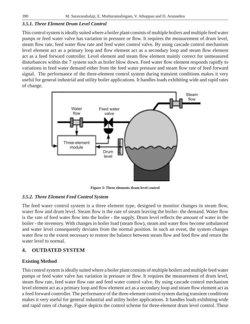
This control system is ideally suited where a boiler plant consists of multiple boilers and multiple feed water pumps or feed water valve has variation in pressure or fl ow. It requires the measurement of drum level, steam fl ow rate, feed water fl ow rate and feed water control valve. By using cascade control mechanism level element act as a primary loop and fl ow element act as a secondary loop and steam fl ow element act as a feed forward controller. Level element and steam fl ow element mainly correct for unmeasured disturbances within the 7 system such as boiler blow down. Feed water fl ow element responds rapidly to variations in feed water demand either from the feed water pressure and steam fl ow rate of feed forward signal. The performance of the three-element control system during transient conditions makes it very useful for general industrial and utility boiler applications. It handles loads exhibiting wide and rapid rates of change.
Waterflow
Feed watervalve
Steamflow
Drumlevel
Three-elementmodule
Figure 3: Three elements drum level control
3.5.2. Three Element Feed Control System
The feed water control system is a three element type, designed to monitor changes in steam fl ow, water fl ow and drum level. Steam fl ow is the rate of steam leaving the boiler- the demand. Water fl ow is the rate of feed water fl ow into the boiler - the supply. Drum level refl ects the amount of water in the boiler - the inventory. With changes in boiler load (steam fl ow), steam and water fl ow become unbalanced and water level consequently deviates from the normal position. In such an event, the system changes water fl ow to the extent necessary to restore the balance between steam fl ow and feed fl ow and return the water level to normal.
4. OUTDATED SYSTEM
Existing Method
This control system is ideally suited where a boiler plant consists of multiple boilers and multiple feed water pumps or feed water valve has variation in pressure or fl ow. It requires the measurement of drum level, steam fl ow rate, feed water fl ow rate and feed water control valve. By using cascade control mechanism level element act as a primary loop and fl ow element act as a secondary loop and steam fl ow element act as a feed forward controller. The performance of the three-element control system during transient conditions makes it very useful for general industrial and utility boiler applications. It handles loads exhibiting wide and rapid rates of change. Figure depicts the control scheme for three-element drum level control. These

391A Novel Approach for Dynamics Compen-sation in Boiler Drum Level Control
are P for the proportional term, I for the integral term and D for the derivative term in the controller. Three-term or PID controllers are probably the most widely used industrial controller. Even complex industrial control systems may comprise a control network whose main control building block is a PID control module. The PID controllers separately calculate the three parameters. The proportional, the integral, the derivative values. The proportional value determines the reaction to the current error. The integral value determines the reaction based on the sum of recent errors as past error. The derivative value determines the reaction based on the rate at which the error has been changing as a future error. And the 100% control valve are maintained the drum level. So the draw backs like fl uctuation and power loss which affects the overall effi ciency.
Control scheme
FlowCalculation
30%CV
100%CV
Drum LevelCompensation
Drum Level DrumPressure
Steam FeedWater
LT-1 LT-2 LT-3 PT-1 PT-2 FT-1 FT-2 FT-1 FT-2
PID1 PID2
Pressure &Density Charty
Drum PressCompensation
Steam FlowCompensation
Feed Water FlowCompensation
Figure 4
Three parameters are measured like drum pressure, steam fl ow and feed water fl ow. Drum level value is measured and then given to the PID 1 and PID2. PID2 is used to control the 30% control valve which is only used for emergency condition and also as single element controller to control level. When we use the 30% control valve we can only generate 10MW of the total 25MW power production capacity, so we always go for 100% control valve Pressure in the boiler drum is measured by the differential pressure transmitter and the value is given to the pressure and density charity. Pressure value is measured and the density can be found out using the pressure and density charity. PID1 controller output is also given to the pressure and density charity to the drum pressure value. According to the steam fl ow and density charity, fl ow is calculated using the calculating function. Calculated fl ow value is then given to the PID3 and also feed water fl ow .PID3 value is given directly to the 100% control valve. Where the Controllers PID1,PID2,PID3 were implemented in a plant with help of Yokogawa DCS centum 3000, all the controllers minimum value of Derivative has been chosen.
Flow calculation
Compensation Flow = Q* Current Flow Q = (Desired Temp * Actual Pressure) / (Desired Pressure * Actual Temp)

392 M. Saravanabalaji, E. Muthuramalingam, V. Athappan and D. Arunnehru
Pressure and Density Charity
Table 1
Drum Pressure Water Density Steam density
0 1 0
45.04 0.791 0.217
61.6899 0.75 0.025
71.57 0.741 0.0305
76.94 0.7322 0.03607
82.62 0.725 0.0395
88.64 0.741 0.0425
101 0.66 0.0522
Drawback of existing scheme
Three element control scheme is one of most control methodology used in a High pressure boilers. Even though the power loss, drum oscillation and high pressure water to spoil the life control valve life time. This dynamics are occurred during the boiler operation it will lead to affect the steam production and boiler performance also affects the coverall plant performance.
5. PROPOSAL SYSTEM
To overcome the drawbacks of existing method of control scheme the implementation of feed water fl ow pressure compensation method is used to which control the water level in boiler drum and overcome the dynamics. Like power loss is reduced, increase the control valve life time and reduced water fl uctuation in the drum. The VFD control is used to achieve the feed water fl ow pressure compensation. VFD will receive the control signal from PID4 based on the signal the frequency variation will leads to drive the pump. Since the feed water pump is controlled using VFD and the pressure is also compensated and level is maintained properly and fl uctuation is also reduced.
Control scheme of proposed system
Three element drum level control is used for the control of water level in boiler drum. Three parameters are measured like drum pressure, steam fl ow and feed water fl ow and there dynamics are reduced. Drum level value is measured and then given to the PID 1 and PID2. PID2 is used to control the 30% control valve which is only used for emergency condition and also as single element controller to control level. When we use the 30% control valve we can only generate 10MW of the total 25MW power production capacity, so we always go for 100% control valve .Pressure in the boiler drum is measured by the differential pressure transmitter and the value is given to the pressure and density charity. Pressure value is measured and the density can be found out using the pressure and density charity. PID1 controller output is also given to the pressure and density charity to the drum pressure value. According to the steam fl ow and density charity, fl ow is calculated using the calculating function. Calculated fl ow value is then given to the PID3 and also feed water fl ow. PID3 value is spitted into two. One is given directly to the 100% control valve and another one is PID4 which has the same characteristics as PID3. A constant pressure is compensated to the PID4 because the pressure of the feed water fl owing in the pipes should be more than the boiler drum pressure. If it is less means the water will not fl ow so we are compensating a constant pressure. Now the PID4 control value is given to the Variable frequency drive. VFD will control the feed water pump and level is being maintained. It can eliminate the more fl uctuation in the boiler drum level and save the power loss. According to the characteristics of pump, it can be found that the fl ux varies due to different motor

393A Novel Approach for Dynamics Compen-sation in Boiler Drum Level Control
speed. On condition that less water is needed in operation, we can decrease the motor speed through the VFD rather than the valve, we can save a lot electricity.
FlowCalculation
30%CV
100%CV
Drum LevelCompensation
Drum Level DrumPressure
Steam FeedWater
LT-1 LT-2 LT-3 PT-1 PT-2 FT-1 FT-2 FT-1 FT-2
PID1 PID2
Pressure &Density Charty
Drum PressCompensation
Steam FlowCompensation
Feed Water FlowCompensation
Figure 5: Control scheme of proposed system
6. VARIABLE FREQUENCY DRIVE (VFD)
Boiler Feed Water Pump Controls
Boiler feed water systems are critical to overall power plant performance, but can be one of the single largest energy consumers in the plant. As electrical demand fl uctuates, the required boiler feed water fl ow rate changes to match make-up water demand. Feed water fl ow is created by a large pump that operates at full speed and a modulating valve opens and closes to vary the fl ow rate supplied to the boiler. This boiler feed water system consisting of a modulating throttle valve to control fl ow rate is effective but requires frequent valve maintenance and wastes energy.
A Better Way
Reduce energy consumption and lower maintenance cost by controlling boiler feed water fl ow with a variable speed drive rather than a throttling valve. Boiler feed water fl ow can be controlled by varying the speed of the electric motor that controls the speed of the pump and modulates the water fl ow to the boiler. By controlling fl ow using a variable speed drive, the electric motor uses much less horsepower and there for less kilowatts as compared to the throttling valve. In this new control scenario, the feed water valve should be 100% open or removed so to not restrict water fl ow. Since the throttle valve is no longer being operated, there is reduced valve maintenance cost. For example, the boiler feed water pump operating at 20% less fl ow (the pump operates 20% slower), can result in a 50% reduction in energy savings (based on the Affi ne nifty Laws).
Pump Flow Control
On large pumps, signifi cant energy savings can be realized by replacing a fi xed speed motor and old fl ow control technology with a variable speed motor. This example is a pump supplying water to a process and driven by a fi xed speed induction motor. The water fl ow is controlled with a diaphragm operated control

394 M. Saravanabalaji, E. Muthuramalingam, V. Athappan and D. Arunnehru
valve controlled by a signal from the process control system (PLC or DCS).If less fl ow is required the valve is partially closed, which reduces the fl ow to the desired value and increases the pump pressure at the same pump speed. This is called fl ow throttling, and the pressure drop across the valve causes energy to be lost. Also since the pump is working against a higher pressure, more energy is required from the motor. The situation is much improved if a variable speed motor, supplied by a variable frequency drive (VFD), is used. The control valve is no longer required since the fl ow is varied by changing the motor speed. The VFD is supplied by 50 or 60 Hertz three-phase power, and creates a three-phase output of any desired frequency. The motor changes speed to match the frequency supplied to it, and drives the pump at this speed, which produces the desired fl ow. To reduce the fl ow there is no throttling and the pump supplies the fl ow against a much lower pressure, so the motor power required is much less. This represents a signifi cant energy savings, especially if the reduced fl ow continues for any extended period.
Power Conversion Power Conversion
OperatorInterfrace
1540
Sine WavePower
VariableFrequency
Power
MechanicalPower
AC MotorVariable
FrequencyController
Figure 5: Working of VFD
Variable Frequency Drive in Thermal Power Plant
The application of the medium voltage variable frequency drive in the large-sized asynchronous motor is just at the initial stage in China, which, however, has been pretty popular in the developed countries.
Main power3-phase ac
Main power3-phase upto 14.4 kV
Induction Motorfixed speed
Pump
Control valve
Output Flow
Pump Inlet Flow
Pump
Pump Inlet Flow
Output FlowVariableFrequency3-phase
Variable Frequency Drive(Dura-Bilt5i MV)
Induction Motorvariable speed
Figure 6: Pump fl ow control
As the development of the electronic components, types of the medium voltage VFD become very diverse. By the topological structure, the medium voltage VFD can be classifi ed as IGBT module serial-connection type, tri-level type and multiple power unit serial-connection type with voltage superposition.

395A Novel Approach for Dynamics Compen-sation in Boiler Drum Level Control
Considering that there will be just a little pressure change, we decided to only reconstruct the 2# water supply pump with the variable frequency drive.
Adopt the mode of one VFD to control one pump, and no need to add power frequency bypass system.Take 4~20mA current of the pressure transmitter from the pumping main as the feedback signal, and
obtain the given frequency from the DCS system.Run signal and stop signal are given by the DCS system.The condition signal of the medium voltage VFD is sent from the control cabinet to the DCS system
for the purpose of instantaneous detection.The pressure value of the pumping main can reach or overrun the requested 6.8MPa after reconstruction.Shut down the by-pass valve of each pump, and the appropriate fl ux can be produced by adjusting the
speed of the motor through the medium voltage VFD.
Close-Loop\Control
Shut down the by-pass valve of each pump, and realize close-loop control by the VFDs PID function, and the DCS system will provide the given 4~20mA corresponding to 0~10MP. And the press transformer on the pumping main will feed back the 0~10MP press signal to the VFD, and to control output torque by PID, so as to adjust the water fl ux.
VFD Control
A VFD controls the speed of an ac motor, which provides fl exibility to the process since speed can be changed easily for process optimization. It takes the fi xed power supplied to it and converts it into a variable frequency and variable voltage source which then feeds a motor. This allows the drive to control the speed and torque the motor produces.
A VFD may enhance the user’s profi tability by improving the process.
7. SIMULATION WORKVFD DESIGN OWNGoto
COLUMN SECTORANGLE VOLTAGE STATUS
Voltage Controller1
SPEEDESTIMATIONGoto1
Goto5
Goto2
Goto4
[s1]
[s2]
[s3]
[s5]
[s6]
Step
Step2
Step1
PID
PID
PID Controller
PIDController1
SaturationAdd2 Transfer Fon1
Transfer Fon3
0.25s + 0.25
0.15s + 1
1
–0.25s + 0.25
Transfer Fon2
Scope1
[s4]
Add
num(s)
den(s)
2s + s2
2s + s2
++
+
+
Figure 7: VFD Using PID Controller
The transfer function and PID controller Values are collected from the plant and same values has been chosen. The proposed system has been simulated in the matlab in the fi g 7. In the three element boiler drum level control the parameters are like level, steam fl ow and water fl ow .The feed forward disturbance is steam fl ow and the cascade is level and feed water fl ow. Level, water fl ow, steam fl ow and control valve
396 M. Saravanabalaji, E. Muthuramalingam, V. Athappan and D. Arunnehru
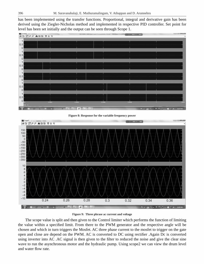
has been implemented using the transfer functions. Proportional, integral and derivative gain has been derived using the Ziegler-Nicholas method and implemented in respective PID controller. Set point for level has been set initially and the output can be seen through Scope 1.
0
1
0.5
0
1
0.5
0
1
0.5
0
1
0.5
0
1
0.5
0
1
0.5
Figure 8: Response for the variable frequency power
0.28 0.3 0.32 0.34 0.360.24 0.26
150100
500
–50–100–150–200–250–300–350
10
8
6
4
2
0
–2
–4
–6
–8
–10
Figure 9: Three phrase ac current and voltage
The scope value is split and then given to the Control limiter which performs the function of limiting the value within a specifi ed limit. From there to the PWM generator and the respective angle will be chosen and which in turn triggers the Mosfet. AC three phase current to the mosfet to trigger on the gate open and close are depend on the PWM. AC is converted to DC using rectifi er .Again Dc is converted using inverter into AC .AC signal is then given to the fi lter to reduced the noise and give the clear sine wave to run the asynchronous motor and the hydraulic pump. Using scope2 we can view the drum level and water fl ow rate.

397A Novel Approach for Dynamics Compen-sation in Boiler Drum Level Control
600
400
200
0
43210
–1
4
2
0
–2
–1
5040302010
00.7 0.8 0.9 10.1 0.2 0.3 0.4 0.5 0.60
Figure 10: Rotor speed, torque, stator current and rotor angle
2.5
2
1.5
1
0.5
0
120
10
80
60
40
20
0
0.6 0.7 0.8 0.9 10.2 0.3 0.40 0.1 0.5
Figure 11: Response for drum level control and feed water fl ow
8. RESULT
The performance of VFD based controllers are evaluated using the considered groups of system and their. comparative responses are shown in Figure 7.5.From the graphs above we can calculate the rise time along with settling time and steady state.
398 M. Saravanabalaji, E. Muthuramalingam, V. Athappan and D. Arunnehru
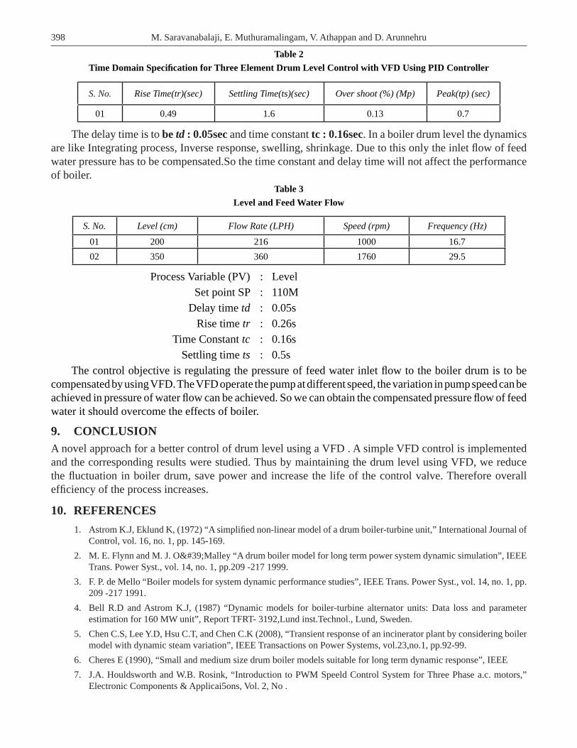
Table 2 Time Domain Specifi cation for Three Element Drum Level Control with VFD Using PID Controller
S. No. Rise Time(tr)(sec) Settling Time(ts)(sec) Over shoot (%) (Mp) Peak(tp) (sec)
01 0.49 1.6 0.13 0.7
The delay time is to be td : 0.05sec and time constant tc : 0.16sec. In a boiler drum level the dynamics are like Integrating process, Inverse response, swelling, shrinkage. Due to this only the inlet fl ow of feed water pressure has to be compensated.So the time constant and delay time will not affect the performance of boiler.
Table 3Level and Feed Water Flow
S. No. Level (cm) Flow Rate (LPH) Speed (rpm) Frequency (Hz)
01 200 216 1000 16.702 350 360 1760 29.5
Process Variable (PV) : Level Set point SP : 110M Delay time td : 0.05s Rise time tr : 0.26s Time Constant tc : 0.16s Settling time ts : 0.5sThe control objective is regulating the pressure of feed water inlet fl ow to the boiler drum is to be
compensated by using VFD. The VFD operate the pump at different speed, the variation in pump speed can be achieved in pressure of water fl ow can be achieved. So we can obtain the compensated pressure fl ow of feed water it should overcome the effects of boiler.
9. CONCLUSIONA novel approach for a better control of drum level using a VFD . A simple VFD control is implemented and the corresponding results were studied. Thus by maintaining the drum level using VFD, we reduce the fl uctuation in boiler drum, save power and increase the life of the control valve. Therefore overall effi ciency of the process increases.
10. REFERENCES 1. Astrom K.J, Eklund K, (1972) “A simplifi ed non-linear model of a drum boiler-turbine unit,” International Journal of
Control, vol. 16, no. 1, pp. 145-169. 2. M. E. Flynn and M. J. O'Malley “A drum boiler model for long term power system dynamic simulation”, IEEE
Trans. Power Syst., vol. 14, no. 1, pp.209 -217 1999. 3. F. P. de Mello “Boiler models for system dynamic performance studies”, IEEE Trans. Power Syst., vol. 14, no. 1, pp.
209 -217 1991. 4. Bell R.D and Astrom K.J, (1987) “Dynamic models for boiler-turbine alternator units: Data loss and parameter
estimation for 160 MW unit”, Report TFRT- 3192,Lund inst.Technol., Lund, Sweden. 5. Chen C.S, Lee Y.D, Hsu C.T, and Chen C.K (2008), “Transient response of an incinerator plant by considering boiler
model with dynamic steam variation”, IEEE Transactions on Power Systems, vol.23,no.1, pp.92-99. 6. Cheres E (1990), “Small and medium size drum boiler models suitable for long term dynamic response”, IEEE 7. J.A. Houldsworth and W.B. Rosink, “Introduction to PWM Speeld Control System for Three Phase a.c. motors,”
Electronic Components & Applicai5ons, Vol. 2, No .