a new vision for smart objects and the internet of things: mobile
TRANSCRIPT

A New Vision for Smart Objects and the Internet of Things:Mobile Robots and Long-Range UHF RFID Sensor Tags
Jennifer WangMassachusetts Institute of Technology
Erik SchluntzHarvard University
Brian OtisUniversity of Washington
Travis DeyleDuke University
Abstract— We present a new vision for smart objects andthe Internet of Things wherein mobile robots interact withwirelessly-powered, long-range, ultra-high frequency radio fre-quency identification (UHF RFID) tags outfitted with sensingcapabilities. We explore the technology innovations driving thisvision by examining recently-commercialized sensor tags thatcould be affixed-to or embedded-in objects or the environmentto yield true embodied intelligence. Using a pair of autonomousmobile robots outfitted with UHF RFID readers, we exploreseveral potential applications where mobile robots interactwith sensor tags to perform tasks such as: soil moisturesensing, remote crop monitoring, infrastructure monitoring,water quality monitoring, and remote sensor deployment.
I. INTRODUCTION
We can generally classify robot sensing into two modal-ities: remote contactless sensing (eg. lasers, cameras, andultrasound) and direct touch (eg. haptics). Researchers havelong speculated about a third sensing modality where “smartobjects” or “smart environments” with embedded computa-tion and sensing can directly measure and report salient in-formation back to a robot. In more recent times, this generalconcept has garnered the moniker “Internet of Things.”
UHF RFID is one compelling technology that speaksdirectly to the Internet of Things vision. Classic UHF RFIDtags contain a small integrated circuit affixed to an antennaand mounted on a flexible substrate. These battery-free tagsharvest all of their power from the wireless signals thatare also used for communication. The tags provide uniqueidentification; are extremely low cost (sub-$0.10 USD each);can be read from several meters away; can co-exist in theenvironment in the hundreds or thousands owing to low-levelanti-collision protocols; and are produced in vast quantitieseach year for logistics applications. Previously, researchersdeveloped UHF RFID tags that also contain general-purposecomputation as well as sensing capabilities [1]. Similarsensorized UHF RFID tags are now commercially available.In this paper, we explore some early prototype applicationsfor these tags and generally explore how these tags could bea boon for robotics.
The contributions of this paper are three-fold. First, weexamine current commercially-available UHF RFID tagswith sensing capabilities. We provide a basic comparison ofthis technology with other direct-sensing technologies suchas Bluetooth Low Energy sensors, and we speculate aboutpotential future robot applications.
Second, we demonstrate the first instance where robotsinteract with sensorized UHF RFID tags: a prototype appli-
Fig. 1. Top Row: An unmanned aerial vehicle (a quadrotor drone) from3D Robotics hovers above a Farsens Hydro tag mounted on a stick. Thedrone uses an attached UHF RFID reader to obtain direct soil moisturemeasurements from the tag. Bottom: An autonomous ground vehicle witha UHF RFID reader approaches a similar Farsens Hydro tag and obtainsdirect soil moisture measurements.
cation that uses commercial moisture-sensing tags for cropmonitoring. We developed a pair of mobile robots (one aerialand one ground, as depicted in Figure 1), which we outfittedwith UHF RFID readers for directly interacting with the sen-sor tags to obtain soil moisture measurements. We examinethe requisite system components and discuss benefits of sucha direct-measurement “smart field” compared to other remotesensing approaches to crop monitoring.
Finally, we report on a number of other experimentswhere we used an unmanned aerial vehicle (UAV) underRC control to (1) deploy sensorized UHF RFID tags intoremote, out-of-reach locations; (2) perform a rudimentarytype of infrastructure monitoring with sensorized tags affixed

Fig. 2. A series of sensorized UHF RFID tags by Farsens (green). From leftto right: resistance sensor, remotely-activated switch, 3-axis accelerometer,remotely-activated LED, magnetometer, pressure sensor. Also, a typicalcommercial UHF RFID tag by Alien Technologies (white) that providesunique identity only.
Bluetooth Low Energy UHF RFIDActive Size Postage Stamp Grain of Sand
Power20mW during TX no TX poweruW during sleep uW at the tagNo reader power 1W+ at reader
Cost at Scale $3 ea. sub-$0.10Lifetime 4-10 years indefinite (battery-free)Comms Bidirectional & push no-
tificationsBidirectional
Fig. 3. Comparing Bluetooth Low Energy and UHF RFID for direct sensingapplications
to a building’s walls; and (3) use sensorized tags in a tree toperform rudimentary crop monitoring.
We recognize that many of these results are preliminary.We explicitly do not address the design of sensorized tags;perform a theoretical analysis of RF propagation; examinethe design of the robots themselves; address RFID systemdesign considerations such as antenna selection; nor do weprovide a detailed evaluation of any one application (eg. soilmonitoring) – each of these considerations has already beencovered in the literature [1], [2], [3]. Instead, our focus is toshow, for the first time ever, how robots can use sensorizedUHF RFID tags to facilitate a number of unique applications.Through these rudimentary prototypes, we hope to impressupon you, the reader, the potential benefits afforded to robotsby these tags and provide a new tool for your toolbox. Webelieve there are myriad possibilities for sensor tags to beapplied in other areas too, such as livestock monitoring,healthcare, and home automation. As the Internet of Thingspervades our lives, it may even become practicable to embedtags in everyday objects, where: cups can inform the robotwhat liquid it contains and in what quantity; clothes canindicate their dirtiness; or food that can indicate its freshnessor spoilage. The rich information provided to robots bydirect, embodied intelligence in the form of UHF RFIDsensor tags could be transformative.
II. RELATED WORK
Roboticists have employed RFID to great effect. Theunique identifier has proved useful for object recognition [4],as a high-confidence landmark in SLAM implementations[5], for waypoint navigation [6], and as a complementarysensing modality for multi-sensor fusion [7]. Many of thesesystems rely on low-frequency (LF) and high-frequency (HF)RFID tags, which have very short read ranges (5-10 cm).In contrast, ultra-high frequency (UHF) tags can be usedfor both short-range operation [8] as well as long-rangeoperation out to several meters [9]. In robotics, UHF RFIDtags have been used for robot localization [10], to locatetagged objects [11], for medication delivery [12], and formanipulation [13].
Previously, researchers developed UHF RFID tags thatcontain general-purpose computation and sensing capabili-ties [1]. Others have developed custom bio-monitoring tags[14], multimedia tags [15], and moisture or temperaturetags that can (for example) help detect inadvertent foodthawing during transportation [16], [17], [18]. These tags arealso starting to see traction outside of academia; standards-compliant, sensorized UHF RFID tags are now becomingcommercially available in small quantities from companieslike Farsens and AMS. These tags have distinct advantages interms of size, cost, and lifetime compared to other actively-transmitting battery-powered sensor technologies, such assensors based on Bluetooth Low Energy; these advantagesare summarized in Figure 3. For example, many sensingtechnologies are fundamentally limited by the capacity ofon-board batteries, resulting in sensor lifetimes measuredin weeks or months or systems that require burdensomeperiodic battery replacement [19]. In contrast, battery-freeUHF RFID tags can have lifetimes on the order of decadessince they harvest nearly all of their operating power from anearby RFID reader. By mounting RFID readers on robotsand placing tags in the environment, system designers canleverage robot mobility to obtain the unique benefits affordedby UHF RFID sensor tags.
In the context of agricultural sensing, remote crop mon-itoring (usually via camera imaging) has already proveduseful [20], and it’s even feasible to have UAVs obtaindirect measurements for applications such as water qualitymonitoring [21]. Inexpensive sensorized UHF RFID tagshave the potential to augment or supplement existing remote-sensing systems to provide precise, direct measurements (eg.for calibration), and could even be used by existing farmequipment to opportunistically obtain relevant agriculturaldata. Direct sensing can make agricultural systems safer,more efficient, more accurate, and more productive [22],[23]. However, agricultural applications frequently involvelarge, expansive areas where wiring for communication andpower is undesirable or impracticable. Wireless sensor net-works have been used collect agriculture data by distributingsensors throughout a field, and transmitting information backto a base station [24], sometimes using more-advanced meshnetworking techniques [19]. These sensor networks have

Fig. 4. Top: A commercially available sensorized RFID tag from Farsens.This tag contains a dipole antenna, RFID chip, SPI companion chip, andsensor input where resistance is measured. Bottom: Experimental setupof sensor tags. The tag was raised on a stake to increase read range.A resistance-measuring probe was inserted into ground to measure soilmoisture.
been shown to provide actionable data that can improvegrowing conditions and irrigation schedules [25], but theystill suffer from battery and cost constraints. UHF RFIDsensor tags are a compelling approach to provide directmeasurements that enhance other remote sensing techniques.
III. SYSTEM COMPONENTS
For the purposes of this work, we focus on a prototypesoil moisture sensing application. Our system was comprisedof three parts: the sensor tag, robot, and ground controlsoftware (GCS). In this section, we’ll explore the relevanthardware and software components of all three.
A. UHF RFID Sensor Tags
We employed sensor tags manufactured by Farsens, whoproduces a number of tags (Figure 2) for sensing: resistance,pressure, light, temperature, moisture, acceleration, magneticfields, etc. For the purposes of our soil moisture sensingapplication, we used commercially-available Farsens HydroTags. We also use Alien Omni-Squiggle tags as a control,though these tags only provide identity (ID) information.
Most UHF RFID tags work by harvesting RF powerbroadcast by a UHF RFID reader. Some tags (including theFarsens tags) have the option of also containing a rechar-gable battery and/or other power harvesting mechanisms forretaining state or data logging when RF power is unavailable;however, we used fully-passive (battery-free) tags for thiswork. Our Farsens tags used a dipole antenna coupled to aspecialized RF integrated circuit (RFIC) created by Farsensthat performs power harvesting and communicates to-and-from the reader using Gen2 UHF RFID protocols. TheRFIC provides electrical power (DC voltage) and a serialperipheral interface (SPI) to a companion sensor chip. In thecase of the Hydro tag, the companion chip senses ambienttemperature and electrical resistance between two leads of aprobe inserted in the topsoil, thereby allowing for accuratesoil moisture measurements – as shown in Figure 4. Thetag also returns a 12-byte unique identifier (ID) in the samefashion as ID-only tags. To broadcast sensor measurementsback to the RFID reader, the RFIC proxies the SPI data overthe Gen2 UHF RFID protocol by reading from and writingto the tag’s internal memory.
Other factors, such as the soil’s chemical make-up andthe ambient temperature, may also affect soil resistivity. Aone-time calibration for the field of interest would probablybe critical for practicable sensor deployments, but is outsidethe scope of this work. For the purposes of our work, wemounted Hydro tags to 0.4m high wooden stakes to improvesignal reliability – see Figure 4.
B. Mobile Robot Hardware
1) Unmanned Aerial Vehicle (UAV): We employed acommercially-available 3D Robotics IRIS quadcopter as ourunmanned aerial vehicle (UAV), as shown in Figure 5.During flight the UAV remained tethered at all times bya 40 lb test nylon cable for both safety and regulatorycompliance. The drone remained in line of sight for alltests, and also featured an emergency human override viaa separate 2.4GHz manual radio remote control (RC). AWA5VJB log-periodic antenna was mounted in a downwardfashion to read tags as the quadrotor hovered nearby a tag.
2) Unmanned Ground Vehicle (UGV): We employed acommercially-available Traxxas Stampede RC car as ourunmanned ground vehicle (UGV), as shown in Figure 6. TheUGV included a sturdy chasis, drivetrain, suspension, rearwheel differential drive, electronic speed controller (ESC),and a servo to control the steering of the front wheels. Weremoved the RC unit that came with the vehicle, and mounteda forward-facing WA5VJB log-periodic antenna to detecttags while approaching their location via ground.
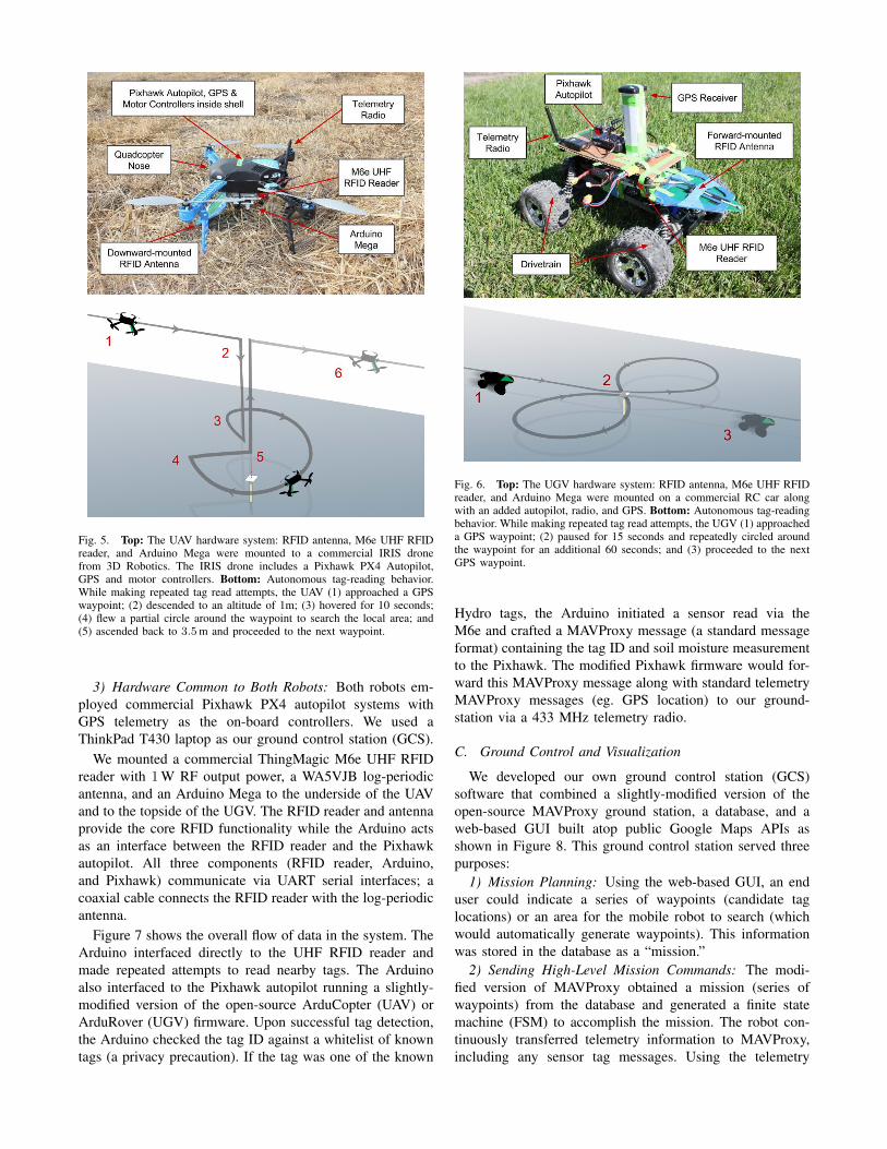
Fig. 5. Top: The UAV hardware system: RFID antenna, M6e UHF RFIDreader, and Arduino Mega were mounted to a commercial IRIS dronefrom 3D Robotics. The IRIS drone includes a Pixhawk PX4 Autopilot,GPS and motor controllers. Bottom: Autonomous tag-reading behavior.While making repeated tag read attempts, the UAV (1) approached a GPSwaypoint; (2) descended to an altitude of 1m; (3) hovered for 10 seconds;(4) flew a partial circle around the waypoint to search the local area; and(5) ascended back to 3.5m and proceeded to the next waypoint.
3) Hardware Common to Both Robots: Both robots em-ployed commercial Pixhawk PX4 autopilot systems withGPS telemetry as the on-board controllers. We used aThinkPad T430 laptop as our ground control station (GCS).
We mounted a commercial ThingMagic M6e UHF RFIDreader with 1W RF output power, a WA5VJB log-periodicantenna, and an Arduino Mega to the underside of the UAVand to the topside of the UGV. The RFID reader and antennaprovide the core RFID functionality while the Arduino actsas an interface between the RFID reader and the Pixhawkautopilot. All three components (RFID reader, Arduino,and Pixhawk) communicate via UART serial interfaces; acoaxial cable connects the RFID reader with the log-periodicantenna.
Figure 7 shows the overall flow of data in the system. TheArduino interfaced directly to the UHF RFID reader andmade repeated attempts to read nearby tags. The Arduinoalso interfaced to the Pixhawk autopilot running a slightly-modified version of the open-source ArduCopter (UAV) orArduRover (UGV) firmware. Upon successful tag detection,the Arduino checked the tag ID against a whitelist of knowntags (a privacy precaution). If the tag was one of the known
Fig. 6. Top: The UGV hardware system: RFID antenna, M6e UHF RFIDreader, and Arduino Mega were mounted on a commercial RC car alongwith an added autopilot, radio, and GPS. Bottom: Autonomous tag-readingbehavior. While making repeated tag read attempts, the UGV (1) approacheda GPS waypoint; (2) paused for 15 seconds and repeatedly circled aroundthe waypoint for an additional 60 seconds; and (3) proceeded to the nextGPS waypoint.
Hydro tags, the Arduino initiated a sensor read via theM6e and crafted a MAVProxy message (a standard messageformat) containing the tag ID and soil moisture measurementto the Pixhawk. The modified Pixhawk firmware would for-ward this MAVProxy message along with standard telemetryMAVProxy messages (eg. GPS location) to our ground-station via a 433 MHz telemetry radio.
C. Ground Control and Visualization
We developed our own ground control station (GCS)software that combined a slightly-modified version of theopen-source MAVProxy ground station, a database, and aweb-based GUI built atop public Google Maps APIs asshown in Figure 8. This ground control station served threepurposes:
1) Mission Planning: Using the web-based GUI, an enduser could indicate a series of waypoints (candidate taglocations) or an area for the mobile robot to search (whichwould automatically generate waypoints). This informationwas stored in the database as a “mission.”
2) Sending High-Level Mission Commands: The modi-fied version of MAVProxy obtained a mission (series ofwaypoints) from the database and generated a finite statemachine (FSM) to accomplish the mission. The robot con-tinuously transferred telemetry information to MAVProxy,including any sensor tag messages. Using the telemetry

Fig. 7. Communication architecture of the system. Data from the RFIDreader is passed through an Arduino, Pixhawk autopilot (AP), and the GCSback to the web dashboard. Commands from the web dashboard are passedthrough the GCS to the Pixhawk AP.
information and FSM, MAVProxy generated high-level com-mands for the robot; it transmitted the commands via the433-MHz radio. Example high-level commands includedactions such as: navigate to GPS coordinate, circle abouta GPS coordinate, change altitude, takeoff, or land.
3) Recording and Visualizing Telemetry: MAVProxy con-tinuously received telemetry messages from the robots (in-cluding GPS location messages and tag ID plus sensormeasurement messages), which it stored in the database.The web-based GUI updated its display based on newinformation.
IV. AUTONOMOUS ROBOT BEHAVIORS
We developed a series of simple robot behaviors to readsensorized UHF RFID tags. These behaviors were based on afew high-level action primitives: navigate to GPS coordinate,circle about a GPS coordinate, change altitude, takeoff, orland. The combination of actions resulted in robot behaviorsto detect tags and obtain sensor measurements.
A. Autonomous UAV Behavior
The UAV search behavior is depicted in Figure 5. Aftertaking off, the drone ascended to a an altitude of 3.5m.It then navigated to the first GPS waypoint (nominallycorresponding to a tag location), traveling at 150 cm/s. Asthe drone flew to a waypoint, it held pitch and roll neutralwhile adjusting yaw so that its nose pointed in the directionof travel.
For each waypoint, the quadcopter performed a searchpattern to counteract GPS error (typically 2m to 3m) andto improve RF connectivity to the tag. When the quadcopterdetected that its GPS location was within 1m of the way-point, it proceeded to hover. Then, it descended to 1.5 m
Fig. 8. Our custom Ground Control Station (GCS). The left hand menugives user control over waypoints and other actions. Waypoints are markedwith grey arrows and linked with a green line showing the trajectory ofthe drone. The past path of the drone is marked with a red line. Blue flagsrepresent locations where a tag was read.
relative to the ground (flat terrain) at a rate of 25 cm/s whileattempting to detect tags. The drone then hovered at 1.5m for15 seconds. If the tag was still not detected, the drone circledabout the GPS coordinate with a radius of 2m at an altitudeof 1.5m. After completing a 270◦ circle without successfullyfinding a tag, the drone ascended to 3.5m at 250 cm/s, exitedthe search behavior, and then either proceeded to the nextwaypoint or exited the mission altogether. At any point, if theUAV received a positive tag reading, it immediately exitedthe search pattern and proceeded to the next waypoint.
It also bears mentioning: The UAV based all altitudemeasurements off the initial takeoff location, and it used abarometer with an altitude precision of approximately ±1m.During the low-hover portions of the behavior, the dronecould be within 0.5m of the ground based on the initialtakeoff location. This poor altitude estimation placed severeconstraints on our ability to autonomously read sensorizedtags. This was a limitation of our chosen UAV, but could bemitigated in real deployments by better sensing (ultrasonicranging, depth cameras, etc.) or better control algorithms.However, again, the drone’s design is outside the scope ofthis paper.
B. Autonomous UGV Behavior
The UGV search behavior is depicted in Figure 6. Thevehicle autonomously navigated to the first GPS waypoint(nominally corresponding to a tag location) such that it wasfacing the desired coordinates. The vehicle stopped when itwas within 1m of the desired GPS location. It waited for15 seconds while attempting to obtain RFID reads. If thetag was still not detected, the robot repeatedly performed asearch pattern wherein it turned some random angle, movedaway from the target GPS location, and then proceeded toreturn to (and face towards) the target GPS location. Afterapproximately 1 minute of random retries, the UGV exitedthe search behavior and either selected another waypointor exited the mission altogether. At any point, if the UGVreceived a positive tag reading, it immediately exited thesearch pattern and proceed to the next waypoint.

Fig. 9. Measured RF power at the tag RFIC terminals gives an estimate ofread range. In the lab, we attached a WA5VJB log-periodic antenna transmitantenna to a 1W RF source and measured the received power obtained usinga Laird UHF S9025-PL patch antenna (circularly polarized, 5.5 dB gain).The Farsens tags’ dipole antenna (linearly polarized) has 2dB less gain, sothe RF power obtained by real tags would be at least 2dB lower comparedto the obtained measurements. In lab, we observed successful RFID sensortag measurements when the RFIC received in excess of −5 dBm; owingto antenna differences, we expect positive dipole tag readings at distanceswhere the patch antenna received in excess of −3 dBm. This correspondsto a 1.5m read range for the dipole Farsens tags, which matches what wesaw in our experiments. The ID-only tags required less power and we wereable to achieve a read range in excess of 3m. A more complete accountingof RF budgets and antenna selection considerations can be found in [3].
V. EXPERIMENTS AND RESULTS
We performed a series of experiments with both robotplatforms using sensorized tags as well as ID-only tags.
A. UAV Experiments
1) Autonomously Reading Sensor Tags: Early lab exper-iments with the log-periodic transmit antenna (like the onecarried by the drone) and a patch receive antenna (not used)suggested that the sensorized Farsens tags would have abest-case read range of just 1.3m (Figure 9) – and perhapsless depending on antenna polarization mismatch. Coupledwith GPS position errors and barometric altitude estimationerrors, we knew that autonomous reading of sensor tagswould be challenging. Because of these constraints, we wereunable to reliably read the sensor tags from the UAV underautonomous control, though we were able to read themunder remote control as discussed later. Improvements to thedrone’s sensing or state estimation, and alternative antennaconfigurations on the drone or tag may have permitted au-tonomous sensor reading behaviors; however, these detaileddesign considerations are well-known in the literature [3] andwere outside the scope of this paper.
2) Autonomous Reading of ID-Only Tags: We planted fiveAlien Omni Squiggle tags in a 40 × 40m open grass fieldat least 10m apart. The flying area was free of obstructionstaller than 1.5 ft, and wind was less than 4mph. We pre-recorded each tag’s GPS location into our ground controlstation and executed the autonomous UAV behavior from theprevious section. We ran two trial missions, which resulted
in positively detecting 5/5 tags (trial 1) and 4/5 tags (trial 2)using the ID-only tags.
3) Remote Control Reading of Sensor Tags: We plantedthree Farsens Hydro tags in the same 40 × 40m opengrass field at least 10m apart. We manually controlled thequadrotor using a 2.4GHz radio. We manually flew betweenthe tags at an altitude of 3.5m, descended to 0.5m, andhovered over each sensor tag until we obtained a sensormeasurement. Obtaining a sensor measurement from the tagduring hover could take up to 30 seconds owing to dronestability under manual control, antenna orientation, and tagcharge-up time. In the end, we were successful at reading all3/3 sensor tags under RC control.
B. UGV Experiments
1) Autonomously Reading Sensor Tags: The UGV hadfewer control issues compared to the UAV. We planted threeFarsens Hydro tags in the field at least 10m apart and gavetheir GPS coordinates as waypoints to the ground controlstation. The tags were elevated on stakes so that the tagwould be at the same height as the RFID antenna mounted onthe vehicle. Because of the shorter read range of the Farsenstags and GPS error, we were only able to read 2/3 of thetags during our experiment.
2) Autonomously Reading ID-Only Tags: We also testedthe UGV platform’s ability to autonomously read ID-onlycommercial tags with a longer read range. We placed threeID-only tags in a field approximately 10m apart and gavetheir GPS coordinates as waypoints. Because of their longerread range, we placed them directly on the ground rather thanelevating them with stakes. The UGV successfully navigatedto and read all 3/3 ID-only tags.
3) Remote Control Reading of Sensor Tags: We placedthree sensor tags in a field approximately 10m apart. Thetags were elevated on stakes so that the tag would be at thesame height as the RFID antenna mounted on the car. Wethen manually drove the UGV to each of tag locations andobtained a reading from each tag. We successfully obtainedsensor measurements from all 3/3 tags.
VI. ADDITIONAL EXPLORATORY EXPERIMENTS
In addition to soil moisture monitoring, we explored aseries of “proof of concept” applications that can helpillustrate the diverse application areas for outdoor sensingusing UHF RFID tags.
A. Deploying Sensor Tags
One compelling use case for battery-free sensor tags isto place tags in hard-to-reach locations where direct humanmeasurements or battery replacement would be difficult (eg.on building exteriors, in treetop canopies, etc.). As shown inFigure 10, we attached a boom arm to our UAV, tipped withan adhesive-backed sensor tag. Under RC control we flewthe quadrotor up to a wall and “poked” the wall with thetag-tipped boom arm. The adhesive on the tag pulled it offthe boom arm and left it placed in the hard-to-reach location;we confirmed our ability to read the sensor tag by re-flyingto the location with the drone-mounted reader.

Fig. 10. Mobile robots could be used to affix sensors in hard-to-reach or difficult-to-service locations, such as retrofitting buildings, bridges, or treetopcanopies with sensor tags. In this case, we outfitted a UAV with a boom arm tipped with an adhesive-backed sensor tag (left). Under RC control, the UAVdeployed the tag and could return later to take measurements (middle and right).
Fig. 11. Drone reading a sensorized tag to assess water quality. Dronescould take sensor measurements in difficult to reach locations over water.
B. Water Quality Monitoring
As shown in Figure 11, we attached one of the resistance-measuring tags to a flotation device and took measurementswith an RC-controlled drone. We suspended the tag’s probeinto the water and obtained conductivity measurements (aproxy for salinity). While this initial implementation is quiterudimentary (and the sensor ill-tuned to the application),the notion of using battery-free sensor tags with virtually-infinite lifetimes has some interesting implications for robotsperforming long-duration water quality monitoring – wheretags could either be floated en masse or attached to commonanchored locations.
C. Infrastructure Monitoring
One oft-discussed applications for drones is to performinfrastructure monitoring: measuring stress, strain, corrosion,wear, etc. for hard-to-reach locations on buildings, bridges,power lines, and dams. Non-contact remote sensing usingcameras and lasers is certainly a compelling capability. Butdirect-measurement using sensor tags offer the possibility totake direct sensor measurements (eg. for calibration), or evento obtain measurements inside the structures by using tagsembedded inside during their construction. As a rudimentaryexample, Figure 12 shows a drone under RC control takingmeasurements from a basic tag on the wall of a building.In this case, the drone measured the moisture content in abuilding support beam, but it would have been equally viableto measure other useful information such as strain or stress.
D. Crop Monitoring
In Figure 13, we show a RC-controlled drone reading alight-sensing tag affixed to a tree. As the price of sensorizedtags approaches that of their ID-only counterparts ($0.10 ea,or lower), we may start to see situations in which monitoringcrops on a plant-by-plant basis becomes viable. Such sensorscould measure plant health, incident solar radiation, waterlevels, fruit ripeness, etc. Indeed, this is an exciting area topursue as sensor tags become pervasive.
VII. DISCUSSION & CONCLUSIONS
In this paper, we provided an overview of recently-commercialized sensor tags, and for the first time, we showedhow robots might utilize such sensor tags. We demonstrateda prototype application for “smart field” soil moisture mon-itoring with some basic experimental evaluation. Finally, wedemonstrated some basic setups that demonstrate compellingfuture possibilities of sensorized tags.
While the possibilities are compelling, current long-rangeRFID systems are not a panacea. Perpetual concerns likeread range, power budgets, and robot control still play asignificant role. Even if ameliorated by battery-assist orenergy-harvesting technologies, there will still be significantchallenges associated with building cost-effective sensorizedtags and integrating them directly into objects and theenvironment.
VIII. ACKNOWLEDGMENTS
We would like to thank Matt Reynolds, John O’Hollaren,and Sid Kandan for their insightful discussions on this topic.
REFERENCES
[1] M. Buettner, B. Greenstein, A. P. Sample, J. R. Smith, and D. Wether-all, “Revisiting Smart Dust with RFID Sensor Networks,” in Proceed-ings of the 7th ACM Workshop on Hot Topics in Networks (HotNets-VII), 2008, pp. 37–42.
[2] K. Finkenzeller and D. Muller, RFID Handbook: Fundamentals andApplications in Contactless Smart Cards, Radio Frequency Identifica-tion and Near-Field Communication. Wiley, 2010.
[3] T. Deyle, “Ultra High Frequency (UHF) Radio-Frequency Identifica-tion (RFID) for Robot Perception and Mobile Manipulation,” Ph.D.dissertation, Georgia Institute of Technology, 2011.
[4] R. Rusu, B. Gerkey, and M. Beetz, “Robots in the kitchen: Exploitingubiquitous sensing and actuation,” Robotics and Autonomous Systems,vol. 56, no. 10, pp. 844–856, 2008.

Fig. 12. Drone taking a measurement for infrastructure monitoring.Sensorized tags could be placed in the support structures of buildings, thetrusses under bridges, or other critical yet hard to reach locations.
Fig. 13. Drone reading a sensorized tag in a tree. Drones could be usedfor forestry monitoring to read sensors in the forest canopy.
[5] A. Kleiner, J. Prediger, and B. Nebel, “RFID technology-based explo-ration and SLAM for search and rescue,” in Proc. of the IEEE/RSJInternational Conference on Intelligent Robots and Systems (IROS),2006, pp. 4054–4059.
[6] J. Bohn and F. Mattern, “Super-distributed RFID Tag Infrastructures,”Lecture Notes in Computer Science, pp. 1–12, 2004.
[7] B. Choi and J. Lee, “Mobile robot localization in indoor environmentusing RFID and sonar fusion system,” in IEEE/RSJ International
Conference on Intelligent Robots and Systems (IROS), 2009, pp. 2039–2044.
[8] T. Deyle, C. J. Tralie, M. S. Reynolds, and C. C. Kemp, “In-HandRadio Frequency Identification (RFID) for Robotic Manipulation,” inIEEE International Conference on Robotics and Automation (ICRA2013), 2013, pp. 1234–1241.
[9] K. Finkenzeller, RFID handbook. Wiley Hoboken, NJ, 2003.[10] D. Joho, C. Plagemann, and W. Burgard, “Modeling RFID signal
strength and tag detection for localization and mapping,” in Pro-ceedings IEEE International Conference on Robotics and Automation(ICRA), Kobe, Japan., 2009, pp. 3160–3165.
[11] T. Deyle, M. S. Reynolds, and C. C. Kemp, “Finding and Navigatingto Household Objects with UHF RFID Tags by Optimizing RF SignalStrength,” in IEEE/RSJ International Conference on Intelligent Robotsand Systems (IROS 2014), 2014.
[12] A. Prakash, J. M. Beer, T. Deyle, C.-A. Smarr, T. L. Chen, T. L.Mitzner, C. C. Kemp, and W. A. Rogers, “Older Adults’ MedicationManagement in the Home: How Can Robots Help?” in ACM/IEEEInternational Conference on Human-Robot Interaction (HRI 2013),2013, pp. 283–290.
[13] H. Nguyen, T. Deyle, M. Reynolds, and C. C. Kemp, “PPS-Tags:Physical Perceptual and Semantic Tags for Autonomous MobileManipulation,” in IEEE/RSJ International Conference on IntelligentRobots and Systems (IROS 2009), Semantic Perception for MobileManipulation Workshop, 2009.
[14] J. S. Besnoff, T. Deyle, R. R. Harrison, and M. S. Reynolds, “Battery-Free Multichannel Digital ECG Biotelemetry Using UHF RFID Tech-niques,” in IEEE International Conference on RFID (RFID 2013),2013, pp. 16–22.
[15] S. J. Thomas, T. Deyle, R. Harrison, and M. S. Reynolds, “Rich-MediaTags: Battery-Free Wireless Multichannel Digital Audio and ImageTransmission with UHF RFID Techniques,” in IEEE InternationalConference on RFID (RFID 2013), 2013, pp. 231–236.
[16] R. Bhattacharyya, “Low-Cost, Passive UHF RFID Tag Antenna-Based Sensors for Pervasive Sensing Applications,” Ph.D. dissertation,Massachusetts Institute of Technology, 2012.
[17] J. Siden, X. Zeng, T. Unander, A. Koptyug, and H.-E. Nilsson,“Remote moisture sensing utilizing ordinary RFID tags,” in Sensors,2007 IEEE. IEEE, 2007, pp. 308–311.
[18] T. Hamrita and E. C. Hoffacker, “Development of a” smart” wirelesssoil monitoring sensor prototype using RFID technology,” AppliedEngineering in Agriculture, vol. 21, no. 1, pp. 139–143, 2005.
[19] R. Beckwith, D. Teibel, and P. Bowen, “Report from the field: resultsfrom an agricultural wireless sensor network,” in Local ComputerNetworks, 2004. 29th Annual IEEE International Conference on.IEEE, 2004, pp. 471–478.
[20] P. J. Zarco-Tejada, V. Gonzalez-Dugo, and J. A. Berni, “Fluorescence,temperature and narrow-band indices acquired from a UAV platformfor water stress detection using a micro-hyperspectral imager and athermal camera,” Remote Sensing of Environment, vol. 117, pp. 322–337, 2012.
[21] A. D. Thaler, “Drones, robotic rovers and citizen scientists join forcesto sample a lakes biodiversity,” Scientific American, 02 2014.
[22] N. Wang, N. Zhang, and M. Wang, “Wireless sensors in agriculture andfood industryrecent development and future perspective,” Computersand electronics in agriculture, vol. 50, no. 1, pp. 1–14, 2006.
[23] L. Ruiz-Garcia, L. Lunadei, P. Barreiro, and I. Robla, “A review ofwireless sensor technologies and applications in agriculture and foodindustry: state of the art and current trends,” Sensors, vol. 9, no. 6,pp. 4728–4750, 2009.
[24] C. Ayday and S. Safak, “Application of wireless sensor networks withgis on the soil moisture distribution mapping,” in Symposium GISOstrava, 2009.
[25] G. Vellidis, M. Tucker, C. Perry, C. Kvien, and C. Bednarz, “A real-time wireless smart sensor array for scheduling irrigation,” Computersand electronics in agriculture, vol. 61, no. 1, pp. 44–50, 2008.