a new thermal integrity method for pile anomaly detection
TRANSCRIPT

A New Thermal Integrity Method for Pile Anomaly Detection
QIANCHEN SUN and MOHAMMED Z.E.B. ELSHAFIE*
ABSTRACT
Anomaly detection is a hot topic in pile construction which is a complex one due to the intrinsic nature of underground structures, such as limited accessibility, large depth and complex soil profile. Several traditional pile integrity tests have been developed before, which, however, cannot give detailed information of anomaly size, nature or pre-cise location. This paper proposes a new thermal integrity testing method that employs distributed temperature sensors and combines concrete heat hydration numerical model. The fundamental principle is that early-age concrete releases heat during curing. If de-fects such as voids, necking, bulging and/or soil intrusion exist inside the concrete body, they will result in local temperature variations. The developed numerical model uses Fi-nite Element Method (FEM) to simulate concrete hydration and heat transfer. The model can be customised for different concrete mixes, pile geometries and built-in anomalies. The modelling results are then compared to field test temperature data. Any temperature disparities indicate potential anomalies of the pile structure. The proposed new test will reduce the cost and increase the accuracy compared to traditional integrity tests. It will be a promising method for the future deep foundation assessment.
INTRODUCTION
As the world becomes more urbanized and the population increases progressively, challenges with land use and large-scale infrastructure suggest that deep foundations (i.e. piles) will become more common — larger and deeper. The associated pile repair and maintenance account for a significant part of the construction cost, which has put more focus on reliable structural health monitoring technologies and data interpretation in recent years.
As for deep foundation, the intrinsic nature of underground structures adds consid-erable difficulties to monitoring their response under various loading and environment conditions [1,2]. Anomalies present in piles, for example voids, soil intrusions, material
__________________________
Q. Sun, Laing O’Rourke Centre for Construction Engineering and Technology,Department of Engineer-ing, University of Cambridge, Cambridge, U.K., Email:[email protected]. Elshafie*, Corresponding Author, Department of Civil and ArchitecturalEngineering, Qatar University, Doha, Qatar., Email: [email protected]
2595
loss or shaft collapse, could result in structure instability and/or durability issues. With-out adequate monitoring techniques and appropriate identification and data interpretationmethods, these anomalies could go undetected. However, the current technologies stillcannot provide an accurate and reliable anomaly detection system [3, 4]. As such, anin-depth study of concrete hydration and heat development is urgently needed.
In this paper, a new thermal integrity testing method is proposed. Distributed tem-perature sensors are deployed on the steel cage to monitor the early-age concrete tem-perature development and to study pile integrity. Aided with numerical simulation, itis hypothesized that a reliable cast in-situ concrete structure interpretation tool for realtime anomaly detection and structural health diagnosis can be developed. Details of thenew integrity testing method are discussed in this paper. The concrete hydration modeland the numerical method are illustrated. Some modelling results of the new method arepresented, followed by conclusions at the end of this paper.
PILE THERMAL INTEGRITY TESTING METHOD
Proposed new method
Cast in-situ piles are prone to have structural defects and imperfections that damagepile structural integrity and thus jeopardize geotechnical load capacity. Piles, geotech-nical elements, that are buried underground, by nature cannot be visually inspected toensure their quality. Therefore, multiple test methods are used worldwide to verify theloading capacity of piles and detect potential anomalies, among which non-destructiveintegrity testing is a common method for pile quality assurance [3,5,6]. Potential anoma-lies - such as voids, soil intrusions and cross-section variations - are expected to be cap-tured through these integrity tests.
Three non-destructive integrity tests are widely used in industry, all of which, how-ever, have significant limitations for pile monitoring. The maximum depth of the PulseEcho test is limited by the presence of stiff soil or rock. The Crosshole Sonic Log-ging (CSL) method cannot provide information of concrete cover outside the steel cage.Gamma-gamma Logging (GGL) only assess very limited area around the access tubes.Therefore, a new reliable and accurate integrity method is necessary.
The proposed new method relies on measuring the amount of heat generated duringconcrete curing. For a cast in-situ concrete element, the heat generation and dissipationare a function of the concrete mix, element geometry, and boundary conditions. If de-fects such as voids, necking, bulging and/or soil intrusion exist inside the concrete body,they will result in local temperature variations. Commonly, a local reduction of tem-perature indicates concrete material loss and is interpreted as a reduced pile diameter.Inversely, a sudden increase of temperature suggests a bulge should occur.
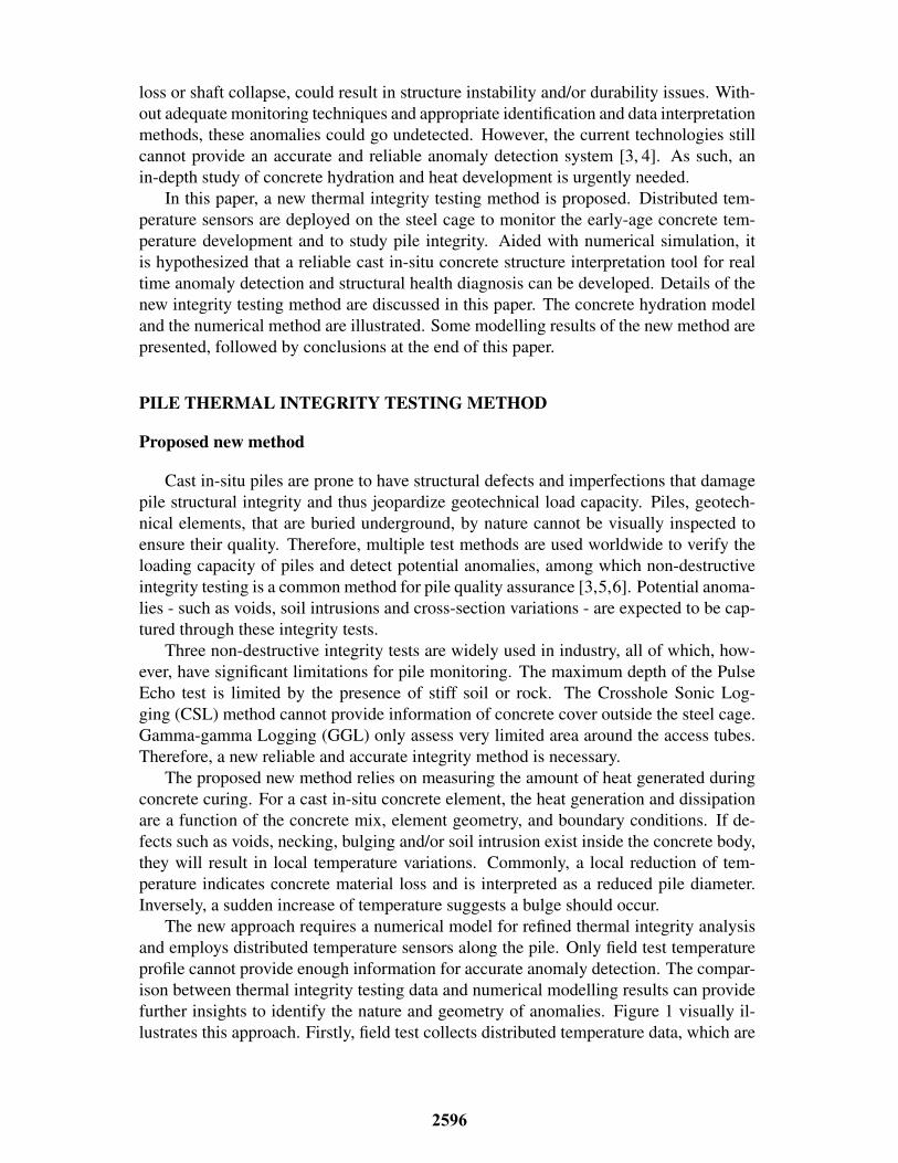
The new approach requires a numerical model for refined thermal integrity analysisand employs distributed temperature sensors along the pile. Only field test temperatureprofile cannot provide enough information for accurate anomaly detection. The compar-ison between thermal integrity testing data and numerical modelling results can providefurther insights to identify the nature and geometry of anomalies. Figure 1 visually il-lustrates this approach. Firstly, field test collects distributed temperature data, which are
2596

Start
Perform TIP test
Collect & process test data
Draw Test Temperature Profiles
Preliminary Anomaly Prediction
Yes
No
Establish FEM numerical model
Add Predicted Anomalies into model
Calculate Temperature distribution;Draw Model Temperature Profiles
Compare Test and Model Profiles(Difference: ∆) ∆ < δ
UpdateAnomaly Prediction
Based onProfile Comparison
Output Anomalies
End
Notes: ∆: Temperature Profile Differenceδ: Allowable error
Notes: ∆: Temperature Profile Differenceδ: Allowable error
Figure 1: Thermal integrity testing anomaly detection system.
processed into temperature profiles versus time. Based on test results and temperaturesignatures, a preliminary prediction of anomalies is given. The numerical model is thenestablished, and its results are compared to the field test temperature. If the differenceexceeds allowable value (depends on geometry, generally 1�C for small diameter piles),the anomaly types and distributions must be re-estimated. Then repeated the above pro-cedures until the model results match the test profiles.
The key procedure of this approach is to build an accurate and reliable numericalmodel, with which pile anomaly detection capacity can be significantly improved. Ce-ment hydration model is reviewed in the following section. The thermally activated andexothermic characteristics of the cement hydration as well as heat transfer mechanismneed to be understood and modelled into the Finite Element Method (FEM) program.
Concrete hydration model
Hydration heat plays an important role in early-age concrete temperature develop-ment [4,7,8]. It is a complex chemical process highly depended on cement composition,reaction time and temperature. On the other hand, the rate and degree of hydration alsosignificantly influences the mechanical properties of hardened concrete [9]. To quantifyhydration production, many scholars have worked on an explicit formulas [10–18].
In this study, the hydration model by De-Schutter and Taerwe [10] is used for de-veloping finite element temperature prediction program. The model has explicit andsimpler mathematical expression. The hydration heat generation rate Q is expressed asa function of the actual cement temperature T (K) and the degree of hydration ↵t (theproportion of the amount of heat released at time t to total heat of hydration).
Q = qmax,20 · c · [sin(↵t⇡)]a · exp(b↵t) · exp(
E
R(1
293� 1
T)) (1)
where a, b and c are hydration parameters dependent on material properties; qmax,20
2597
Start
Define material properties;Build geometry model.
Define ෨𝑇𝑖𝑛𝑖, ∆𝑡, 𝑡𝑒𝑛𝑑, 𝛼𝑢, ෨𝑄𝑡𝑜𝑡𝑎𝑙
Initialise iteration𝑛 = 1, 𝑡 = 0, 𝛼 = 0.001, ෨𝑄𝑐𝑢𝑚 = 0
(Loop over all elements)
𝑞𝑖 = 𝑄𝑟𝑎𝑡𝑒(𝛼𝑖, 𝑇𝑖𝑛𝑖_𝑖)𝑄𝑐𝑢𝑚_𝑖 = 𝑄𝑐𝑢𝑚_𝑖 + 𝑞𝑖 ⋅ ∆𝑡
𝛼𝑖 = 𝑄𝑐𝑢𝑚_𝑖/𝑄𝑡𝑜𝑡𝑎𝑙
Compute element matrix 𝐌𝐌,𝐊𝐌, 𝐅
𝑛 = 𝑛 + 1𝑡 = 𝑡 + ∆𝑡
෩𝐓𝒏+𝟏 = solve(ሚ𝐋\ሚ𝐛)
𝛼 < 𝛼𝑢
(Loop over all elements)
𝑞𝑖 = 𝑄𝑟𝑎𝑡𝑒(𝛼𝑖, 𝑇𝑖)𝑄𝑐𝑢𝑚_𝑖 = 𝑄𝑐𝑢𝑚_𝑖 + 𝑞𝑖 ⋅ ∆𝑡
𝛼𝑖 = 𝑄𝑐𝑢𝑚_𝑖/𝑄𝑡𝑜𝑡𝑎𝑙
Compute 𝐌𝐌,𝐊𝐌, 𝐅
Compute ሚ𝐋, ሚ𝐛Compute global matrix ሚ𝐋, ሚ𝐛
𝑡 < 𝑡𝑒𝑛𝑑
End
Yes
No
No
Yes
(Loop over all elements)
𝑞𝑖 = 0𝛼𝑖 = 𝛼𝑢
Compute 𝐌𝐌,𝐊𝐌, 𝐅
Apply boundary conditionDirichlet: ሚ𝐛𝒊 = Tb
Neumann: ሚ𝐛 = ሚ𝐛 + ሚ𝐟𝒒
Apply boundary conditionDirichlet; Neumann.
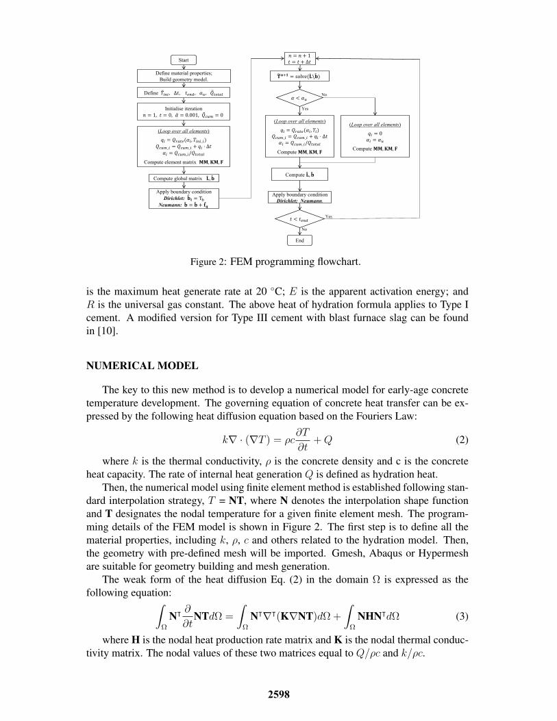
Figure 2: FEM programming flowchart.
is the maximum heat generate rate at 20 �C; E is the apparent activation energy; andR is the universal gas constant. The above heat of hydration formula applies to Type Icement. A modified version for Type III cement with blast furnace slag can be foundin [10].
NUMERICAL MODEL
The key to this new method is to develop a numerical model for early-age concretetemperature development. The governing equation of concrete heat transfer can be ex-pressed by the following heat diffusion equation based on the Fouriers Law:
kr · (rT ) = ⇢c@T
@t+Q (2)
where k is the thermal conductivity, ⇢ is the concrete density and c is the concreteheat capacity. The rate of internal heat generation Q is defined as hydration heat.
Then, the numerical model using finite element method is established following stan-dard interpolation strategy, T = NT, where N denotes the interpolation shape functionand T designates the nodal temperature for a given finite element mesh. The program-ming details of the FEM model is shown in Figure 2. The first step is to define all thematerial properties, including k, ⇢, c and others related to the hydration model. Then,the geometry with pre-defined mesh will be imported. Gmesh, Abaqus or Hypermeshare suitable for geometry building and mesh generation.
The weak form of the heat diffusion Eq. (2) in the domain ⌦ is expressed as thefollowing equation:
Z
⌦
N| @
@tNTd⌦ =
Z
⌦
N|r|(KrNT)d⌦+
Z
⌦
NHN|d⌦ (3)
where H is the nodal heat production rate matrix and K is the nodal thermal conduc-tivity matrix. The nodal values of these two matrices equal to Q/⇢c and k/⇢c.
2598
The equation is then discretised into many time steps. The simplified formula isobtained bellow:
(MM4t
+ KM)Tn+1 =MM4t
Tn + F (4)
where MM, KM and F are mass matrix, stiffness matrix and force matrix respec-tively, which represent the domain integration in Eq. (3). The above element matrixform is then expanded to the global matrix in the domain ⌦ as shown in Eq. (5).
eL eTn+1
= eR eTn+ eF = eb (5)
While implementing the program, note that the initial degree of hydration shouldbe set as a small value instead of zero, or else run time error will occur. Before eachtime loop, it is necessary to check whether the degree of hydration of each element isless than the ultimate degree of hydration. If not, the heat production rate shall returnto zero. All the notations in the flowchart with tilde (˜) are the global matrix, and boldnotations mean element matrix. The nodal number is represented by subscript i. Thesystem temperature eT is updated in each iteration.
MODELLING RESULTS
Hydration model setups
Following FEM modelling technique in the previous section, a hypothetical casestudy using this method is presented in this section. The two-dimensional FEM mod-elling results are demonstrated. The heat hydration model by [10] is used to simulatetemperature development of early age concrete during curing. The heat production rateis expressed in Eq. (1).
Five basic properties of theconcrete and ambient environment are listed in Table I.In this hypothetical case, cement is the only source of hydration heat in the concrete.It takes up about 13% of concrete by weight in this hypothetical case study. Thus,the maximum heat production rate and total released heat for concrete equal 13% ofpure cement qmax.20 (cement). To set the parameter in line with FEM programming,cement heat generation by weight is then converted to heat generation by volume qmax.20
(concrete), which is 13% ⇥ qmax.20 (cement) ⇥ ⇢. Hence, the values of all hydrationmodel parameters are obtained and listed in Table II.
The hypothetical case is a cylinder pile with a diameter of 400 mm. The height is 2meters. The concrete is cast in a semi-adiabatic environment, and circumferential bound-
TABLE I: PARAMETERS OF MATERIAL PROPERTIES
Parameters ⇢ (kg/m3) c (J/kg.K) k (W/m.K) hc (W/m.K) Tenv (K)Values 2200 1000 1.0 1.2 288
TABLE II: PARAMETERS OF HYDRATION MODEL
Parameters a b c qmax,20 (J/m3s) Qtotal (J/m3) E (J/mol) R (J/mol.K)Values 0.667 3.0 2.6 617 77.22⇥ 106 33500 8.31
2599

-0.25 -0.2 -0.15 -0.1 -0.05 0 0.05 0.1 0.15 0.2(m)
-0.25
-0.2
-0.15
-0.1
-0.05
0
0.05
0.1
0.15
0.2
0.25
(m)
Mesh of Column Cross-Section
Artificialanomaly
(a) Geometry mesh
0 10 20 30 40 50 60 70Time (h)
15
20
25
30
35
40
Tem
pera
ture
(°C
)
Temperature Development for different anomaly size
0%4%9%16%25%
(b) Temperature development
Figure 3: Two-dimensional FEM Model
ary heat flux coefficient hc is 0.5 W/m.K. Distributed temperature sensor is attached onthe steel case which is 25mm from concrete cover.
Two-dimensional modelling
In this two-dimensional model, artificial anomalies with various sizes will be built.Figure 3a shows the geometry mesh discretised by 3-node triangular elements. Thehollow section in the middle represents the anomaly with poor concrete quality and/orair bubble. As the pile is relative long (2m) compared to the diameter (0.4m), it isreasonably accurate to employ 2D hypothesis for concrete heat hydration simulation.
This hypothetical case focuses on investigating the influence of anomaly size on thetemperature variation. Anomalies of different sizes are built in the geometry, namely 4%,9%, 16% and 25% of the cross-section area. One control geometry without any anomalyis also simulated. The distributed temperature sensor is attached to the steel cage, whichis located at 25mm from concrete cover. Figure 3b shows the temperature developmentdue to hydration heat transfer at the sensor location. The line with the star markersindicates the control pile temperature development. As the size of anomaly increases,the temperature drops more evidently. The temperature variation due to anomalies is upto 7 �C at 40 hours.
Two-dimensional axisymmetric modelling
The axial symmetry of concrete pile allows the use of one-dimensional axisymmetricmodel. The model is expanded to two-dimensional axisymmetric model to simulate 3Deffect. The geometry mesh discretised by 3-node triangular elements is shown in Figure4a. The height of the pile is 2m. The central anomaly height is 400mm, with a radius of80 mm. Heat flux on the top and bottom boundary is 0.5 W/m.K.
In this model, the distributed temperature is parallel to the pile boundary at 25mm.Figure 4b demonstrates the temperature profile due to early-age concrete hydration atdifferent time. The initial temperature is 15 �C, and it gradually raise to the maximum
2600

-0.5 0 0.5(m)
0
0.2
0.4
0.6
0.8
1
1.2
1.4
1.6
1.8
2
(m)
Mesh of Column Axisymmetric Cross-Section
Artificialanomaly
Distributedtemperaturesensor
(a) Geometry mesh
25 26 27 28 29 30 31 32 33 34 35 36Temperature (°C)
0
0.2
0.4
0.6
0.8
1
1.2
1.4
1.6
1.8
2
Tim
e (h
)
Temperature Profile of Early-Age Concrete
20h25h30h35h
(b) Temperature development
Figure 4: Two-dimensional axisymmetric FEM Model
temperature around 40 hours. At the 1m height, temperature drops evidently in thetemperature profile. As central anomaly does not release heat, a decrease of 2.5 �C onthe temperature profile (Figure 4b) indicates a potential defect at that location.
CONCLUDING
A new anomaly-detection system for cast in-situ concrete structures is presented inthis paper. The new method compensates the limitations of traditional integrity test-ing technologies. It makes accurate and reliable anomaly detection possible. The newmethod also has the potential to identify pile defect size, nature and precise location.
The method employs Finite Element Method to model early-age concrete hydrationand heat transfer within the concrete body. The concrete hydration model developed byDe Schutter is able to accurately simulate heat production rate during the whole curingprocess and compatible for both Type I and Type III cement. The temperature devel-opment of the concrete body is predicted by FEM program, which has demonstrated itscapacity to capture anomalous temperature profile and thus detect anomalies.
The new thermal integrity testing method shows good promise and hence good po-tential to localise and identify anomalies for pile foundation. It is anticipated that thismethod, with continuous research and further refinement, will greatly facilitate deepfoundation assessment with a lower cost and higher accuracy.
ACKNOWLEDGEMENT
This work was performed in the framework of ITN-FINESSE, funded by the Euro-pean Unions Horizon 2020 research and innovation program under the Marie Skodowska-Curie Action grant agreement n 722509. The corresponding author Dr. MohammedElshafie would like to acknowledge the support of Qatar University for attending thisconference.
2601

REFERENCES
1. Matsumoto, T., P. Kitiyodom, H. Matsui, and Y. Katsuzaki. 2004. “Monitoring of loaddistribution of the piles of a bridge during and after construction,” Soils and foundations,44(4):109–117.
2. Kister, G., D. Winter, Y. M. Gebremichael, J. Leighton, R. A. Badcock, P. D. Tester, S. Kr-ishnamurthy, W. Boyle, K. Grattan, and G. F. Fernando. 2007. “Methodology and integritymonitoring of foundation concrete piles using Bragg grating optical fibre sensors,” Engi-neering Structures, 29(9):2048–2055.
3. Zhang, H. L. and C. T. Davie. 2013. “A numerical investigation of the influence of porepressures and thermally induced stresses for spalling of concrete exposed to elevated tem-peratures,” Fire Safety Journal, 59:102–110.
4. Rui, Y., C. Kechavarzi, F. O’Leary, C. Barker, D. Nicholson, and K. Soga. 2017. “Integritytesting of pile cover using distributed fibre optic sensing,” Sensors, 17(12):2949.
5. Phan, L. T., J. R. Lawson, and F. L. Davis. 2001. “Effects of elevated temperature exposureon heating characteristics, spalling, and residual properties of high performance concrete,”Materials and structures, 34(2):83–91.
6. Zou, X., A. Chao, Y. Tian, N. Wu, H. Zhang, T. Yu, and X. Wang. 2012. “An experimentalstudy on the concrete hydration process using Fabry–Perot fiber optic temperature sensors,”Measurement, 45(5):1077–1082.
7. Ruiz, J. M., A. K. Schindler, R. O. Rasmussen, P. K. Nelson, and G. K. Chang. 2001. “Con-crete temperature modeling and strength prediction using maturity concepts in the FHWAHIPERPAV software,” in Seventh International Conference on Concrete Pavements. TheUse of Concrete in Developing Long-Lasting Pavement Solutions for the 21st CenturyInter-national Society for Concrete Pavements, vol. 1.
8. Rui, Y. and M. Yin. 2017. “Thermo-hydro-mechanical coupling analysis of a thermo-activediaphragm wall,” Canadian Geotechnical Journal, 55(5):720–735.
9. Neville, A. M. 1995. Properties of concrete, Pearson Education India.10. De-Schutter, G. and L. Taerwe. 1995. “General hydration model for Portland cement and
blast furnace slag cement,” Cement and Concrete Research, 25(3):593–604.11. De-Schutter, G. and L. Taerwe. 1996. “Degree of hydration-based description of mechanical
properties of early age concrete,” Materials and structures, 29(6):335.12. Schindler, S. K. 2004. “Effect of temperature on hydration of cementitious materials,” Ma-
terials Journal, 101(1):72–81.13. Schindler, A. K. and K. J. Folliard. 2005. “Heat of hydration models for cementitious mate-
rials,” ACI Materials Journal, 102(1):24.14. Riding, K. A., J. L. Poole, K. J. Folliard, M. C. Juenger, and A. K. Schindler. 2011. “New
Model for Estimating Apparent Activation Energy of Cementitious Systems.” ACI MaterialsJournal, 108(5).
15. Tomosawa, F. 1997a. “Development of a kinetic model for hydration of cement,” Proc. ofthe 10th Int. Cong. on the Chem. of Cem., Gothenburg, Sweden.
16. Tomosawa, F., T. Noguchi, and C. Hyeon. 1997b. “Simulation model for temperature riseand evolution of thermal stress in concrete based on kinetic hydration model of cement,” inProceedings of tenth international congress chemistry of cement, vol. 4, pp. 72–75.
17. Park, K. B., T. Noguchi, and J. Plawsky. 2005. “Modeling of hydration reactions using neuralnetworks to predict the average properties of cement paste,” Cement and Concrete Research,35(9):1676–1684.
18. Wang, X. Y. and H. S. Lee. 2010. “Modeling the hydration of concrete incorporating fly ashor slag,” Cement and concrete Research, 40(7):984–996.
2602