a new practical characterization system for use in rock engineering
TRANSCRIPT

RMi - A NEW PRACTICAL CHARACTERIZATION SYSTEM FOR USE INROCK ENGINEERING
RMi - et nytt system for å karakterisere bergmasser for bruk i praktisk bergteknikk
Arild Palmström, Berdal Strömme a.s., Sqndvika, Norge
1. INTRODUCTION
"Provision of reliable input datafor engineering design of structures in rock is one ofthe most dfficult tasksfacing engineering geologists and design engineers."Z.T.Bieniawski, 1984
In addition to Bieniawski (1984), several other authors like Hoek and Brown (19S0) andNieto (1983) and have indicated a need for a strength charqcterization of rock masses.The Rock Mass index (RMÐ has been worked out to satisfu this need and for improvingthe methods of rock mass descriptions, including better practical guidelines forobtaining numerical observation al data.
Rock masses are composed of rocks penetrated by discontinuities. With great diversityboth in the composition of the intact rock and in the nature and extent of thediscontinuities, rock masses exhibit an enoÍnous variation range in structure as well ascomposition. This creates a great challenge when characterizing such complexmaterials. In addition, as reliable tests of the strength of rock masses are impossible orso difficult to carry out with today's technology, rock engineering is currently basedmainly on qualitative, descriptive data found from observations. These descriptive datahave to be converted into numerical values to make calculations in rock engineeringpossible.
2. THE ROCK MASS rNDEX (RMi)
Construction materials, such as steel and concrete, commonly used in civil engineeringand mining are mostly characteúzed by their strength properties. This basic property ofthe material is used in the engineering and design. In rock engineering, no such specificstrength characterization of the rock mass is in common use. The Rock Mass index isintroduced to characteizethe strength of the rock mass to be suitable for application inrock engineering and other types of calculations associated with construction in rock.An important issue has been to use parameters in the RMi which have the greatestsignificance in engineering. This is described in this section.

2.I On the selection of the parameters used in the RMi
Figure I shows rock mass. Hoek et al. (1992). are of11¡ :fpl^P inted rockr, _urr.. *.'"oniíål"¿ ¡,me blocK-' shap haracteristics of the block determinedDy me lntersectr
weak, the properties of the intact rock may strongly influence the overall behaviour ofthe rock mass. The intact rock properties are also important if the joints are discon-tinuous.3)
size end termination of the joints, g¡ven as the factor 0L)friction of the block faces, given as iointroughness facror (R) anci ¡äiiri'ànirãiän tactor ûn)strength of intact rock, given as itsuniaxial compressive strength (o.)size of the block (Vb), given in m3
Figure I Idealized structure of a typical rock mass and the main parameters which are applied in theRML (from palmstrr)m, 1995).
Although rock mass properties in many cases are governed by joints, rocks propertieshave been a major factor in the formation and devãlopment orirre aciual ¡oints.'In thisrespect petrological data can give useful information on the properties jointing
t) Th" tt't 'joint' has been used for most natural discontinuities which have thickness smaller than approx.0'l m' Thus, joints cover fissures' partings, fractures, natural cracks, as well as many shears and seams.
') Joints and other types of discontinuities divide the rocks into blocks.
3 ) Discontinuous joints end in massive rock.
SURFACE WTH JOIIITS DEUHMNG BLOCKS
40

V-
(Franklin, 1970; Piteau,I9l0). A concise rock description accompanied by jointingobservations will, in addition to geology and the type of material at the site, inform thereader of the probable behaviour of the ground.
As indicated in Figure I, the RMi makes use of the following input parameters:. compressive strength of intact rock;. block volume; ando joint characteristics, as given by its roughness, alteration, and size.The combination of these parameters, included in the RMi, is shown in Figure 2.All these are intrinsic parameters of the rock mass. The need to use such parameters incharacterizing the properties of rock masses has earlier been stressed by Deere et al.(1969) and Patching and Coates (1968).
Figure 2 The input parameters to the RMi and their combination (from Palmström, ;,995).
Principally, the RMi is based on the reduction in strength of a rock caused by jointingand is expressed as:
RMi: o.' JP eq.(l)
where o. : the uniaxial compressive strength of intact rock measured on 50 mm samples;JP : the jointing parameter which is a reduction factor representing the block size and
the condition of its faces as represented by their friction properties. In addition, ascale factor forthe size of the joints have been included, as shown in Figures 1
and2.
The influence of JP has been found by using calibrations from test results. Because ofproblems of obtaining compression test results on rock masses at a scale similar to thatof typical rock works, it was possible to find appropriate data from only eight large scaletests and one back analysis. Three of these are from Sweden, provided with kind helpfrom Norbert Krauland, Boliden Mines and Bengt Leijon, Conterra AB. These testresults have been used to arrive at the following mathematical expression:
UNIAXIALCOMPRESSIVE
ETRENGTHc.
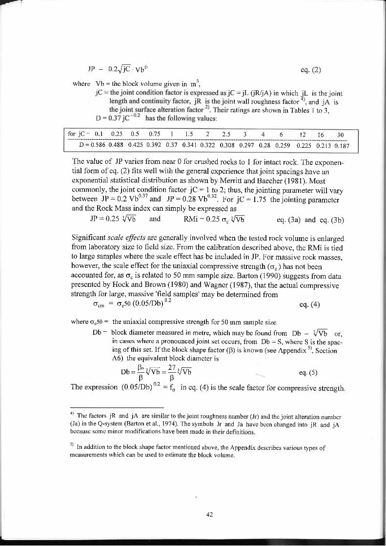
JP : o.2Jjc .vuD eq.(2)
where Vb = the block volume given in m3,jC = C: jL (iR/jA) in which jL is the joint
nt wall roughness factor a), and jA isratings are shown in Tables I to 3,
ES:
The value of JP vades from near 0 for crushed rocks to 1 for intact rock. The exponen-tial form of eq. (2) fits well with the general experience that joint spacings have anexponential statistical distribution as shown by Merrifi and Baecher (1981). Mostcommonly, the joint condition factor jC : I to 2; thus, the jointing parameter will varybetween JP:0.2 vbO37 and JP:0.28 vb0'32. For jc : I.ls the jointing parameterand the Rock Mass index can simply be expressed as
JP:0.25 '.,F- and RMi:0.25 o. VVb eq. (3a) and eq. (3b)
Significant scale effects are generally involved when the tested rock volume is enlargedfrom laboratory size to field size. From the calibration described above, the RMi is tiedto large samples where the scale effect has be included in JP. For massive rock masses,however, the scale effect for the uniaxial compressive strength (o. ) has not beenaccounted for, as o. is related to 50 mm sample size. Barton (1990) óuggests from datapresented by Hoek and Brown (1980) and V/agner (1987), that the actual compressivestrength for large, massive 'field samples' may be determined from
o.,n : o.5o (0.05iDb) o 2
A6) the equivalent block diameter is
ob=&Vvb = " {vapp
where o.50: the uniaxial compressive strength for 50 mm sample size
Db: block diameter measured in metre, which may be found from Db : ,JVb or,in cases where a pronounced joint set occurs, from Db: S, where S is the spac-ing of this set. If the block shape factor (B) is known (see Appendixs), Section
eq.(4)
eq,(s)
The expression (0.05/Db) o t : f" in eq. (4) is the scale factor for compressive strength.
o) Th" factors jR and jA are similar to the joint roughness number (Jr) and the joint alteration number(Ja) in the Q-system (Barton et al., 1974). The symbols Jr and Ja have been changed into jR and jAbecause some minor modifications have been made in their definitions.
5) In addition to the block shape factor mentioned above, the Appendix describes various types ofmeasurements which can be used to estimate the block volume.
for jC: 0.1 0.25 0.5 0.75 I l5 2 )5 J 4 6 t2 l6 30
D :0.586 0.488 0.425 0.392 0.37 0.341 0.322 0.308 0.297 0.28 0.259 0.225 0.213 0.187
42

t-
Eq. (4) is valid for sample diameters up to some metres, and may, therefore, be appliedfor massive rock masses.
TABLE ] THE RATINGS OF THEJOINT ROUGHNESS FACTOR (JR) FOUND FROMSMOOTHNESS AND WAVINESS (From Palmström, 1995)
similar
appearance
ma¡ked st¡iations.
TABLE 2 CHARACTENZATION AND RATING OF THE JOINT ALTERATION FACTOR (JA),(from Palmstöm (1995)(jA is similar to Ja in the Q-system, except for the grade of alteration)
system (Bieniawski, 1973)
(The rat 'R are to Jr in the
small scalesmoothness ofjoint surface
larse scale waviness of ioint nlaneplanar slightly
undulatingstrongly
undulatingstepped interlocking
(large scale)
very roughroughslightly rough
smoothoolishedslickensided')
J21.5
I0.75
0.6 - 1.5
43
2
64J
755
4
964.5
1.5I
| -2
22.531.5 2 2.5
2.5-5t.s-3 2-4For filled joints: jR = I For inegula¡joints a rating of jR:5 is suggested
on tne presence
A. CONTACT BETWEEN THE TWO ROCK WALL SURFACES
TERM DESCRIPTION jA
Clean joints-Healed or "welded" joints-Fresh rock walls-Alteration ofjoint wall:
. I grade more altered
. 2 grades more altered
Coating or thin filling-Sand, silt, calcite etc.-Clay, chlorite, talc etc.
Softening, impermeable hlling (quartz, epidote etc.)No coating or filling on joint surface, except for staining
Thejoint surface exhibits one class higher alteration than the rockThe joint surface shows two classes higher alteration than the rock
Coating of friction materials without clayCoating of softening and cohesive minerals
0.75I
24
J
4
B. FILLED JOINTS WITH PARTIAL OR NO CONTACT BETWEEN THE ROCK WALLSURFACES
TYPE OF FILLINGMATERIÄL
DESCRIPTION
Partial wallcontact
thin fillinss(< s mmry)
jA
No wallcontact
thick fillingor gouge
jA
-Sand, silt, calcite etc.-Compacted clay materials-Soft clay materials-Swelling clay materials
- Filling of friction materials without clay- "Hard" filling of softening and cohesive materials- Medium to low over-consolidation of filling- Filling material exhibits clear swelling properties
46
8
8-12
8
l0t2
t2-20Rq<ed fhinkness diviqinn ski lQ7Jolnt
43

,r=1
TABLE 3 THE JOINT SIZE AND CONTINUITY FACTOR ( (from Palmström, I 995).
occufs a¡i a s
â
u¡Ifo
vooo
Ea!ocÊIoa,
!ot,
aE¡o
0060.05
0-04t
0.00001
03
0.0001 0.001
l-0 01gF,E€ sÌ;i -!Es \"
s7 | 2 3 57r 23 57 | 23 57 2g 57 23 s70.01 0.,r I
JOtNT|NG PARAMETER (JP)Figure 3 The jointing Parameter (JP) found from the joint condition factor (jC) and various measure-
ments of iointing intensity (Vb, Jv, RQD). The determination of JP from Vb (or ReD or Jv) inthe examples shown in section 3 are indicated (from palmström, t996a).
JOINTLENGTH
jLcontinuous
joints
bedding/fol iation partingsjointjointioint
filled joini ), seam*) or shear')
3
2I
0.7 50.5
<0.5m0.1 - 1.0 m
1- lOm10-30m>30m
very shorlshort/smallmediumlong/largevery long/large

From Figure 3 the jointing parameter (JP) can be found using the block volume (Vb)and the joint condition factor (C). As shown in the upper left part of the diagram, thevolumetric joint count (Jv) for various joint sets (and/or block shapes) can be usedinstead of the block volume. This is based on the correlations given in the Appendix.Also, the RQD can be used, but its inability to characterise massive rock or highlyjointed rock masses leads to a reduced quality of the JP.
The classification of RMi is presented in Table 4. Numerical values alone are seldomsuffrcient for cha¡actenzing the properties of a complex material such as a rock mass.Therefore, the RMi and its parameters should be accompanied by supplementary descrip-tions.
TABLE 4 CLASSIFICATION OF RMi. (from Palmstrr)m, 99
TERM
RMi valuefor RMi related to rockmass strength
Extremely lowVery lowLowModerateHighVery highExhemely high
Extremely weakVery weakWeakMediumStrongVery strongExtremely strong
< 0.001
0.001 - 0.01
0.01 - 0.1
0.1 -l1-10
l0 - 100> 100
The RMi can be applied in various types of rock engineering with adjustment forfeatures related to the particular project or utilisation of the rock. These applications arebriefly described in Section 4.3.
3. EXAMPLES
The values of the jointing parameter (JP) found in the following examples are shown inFigure 3.
Exømple IThe block volume has been measured as Vb:0.003 m3 (:3 dm3). As given in Tables 1
to 3, the joint condition factor jC:0.75 is determined from:- the rough joint surfaces and small undulations of the joint wall which gives jR:3;- the clay coated joints, i.e. jA:4; and- the 3 - l0 m long, continuous joints, which gives jL : I .
Applying the values for vb and jc in Figure 3, a value of Jp : 0.02 is found. 6) with acompressive strength of the rock o.: 50 MPa, the value of RMi :0.02. 150:3 (high)
u) Usittg eq.(2) a value of JP:0.018 is found

Example 2The block volume is Vb:0.6 m3. The joint condition factor jC :2 is determined fromTables 1 to 3, based on:
-smooth joint surfaces and planar joint walls which gives jR: 1;-fresh joints, jA : 1; and I to 10 m long discontinuous joints, i.e. jL:2.
From Figure 3 the value JP : 0.25 is found. t) with a compressive strength o. : 50MPa of the rock, the value of RMi :12.5 (very high).
Example 3Values of RQD : 50 and jC:0.2 give JP : 0.007
Example 4Two joint sets with average spacings 0.3 m and 1 m, and some random ioints occur inan area. The volumetric joint count is Jv : 1/0.3 + lll + 0.5 8) : 4.5With a joint condition factor jC : 0.5 the jointing parameter Jp :0.12 (by using thecolumn for 2 to 3 joint sets in Figure 3).
Example 5The following jointing features are measured: only one joint set with average spacingS : 0.45 m, and a joint condition factor jC : 8. For this massive rock it is seen inFigure 3 that the value of JP is determined from the scale factor for compressivestrength t:0.45. For a rock with o": 130 Mpa the value of RMi : 59.6 (very high).
4. DISCUSSION
The RMi can be applied in various types of rock engineering with a-djustment forfeatures related to the particular project or utilisation of the rock These applications arebriefly mentioned in Section 4.3.
4.1 Benefits - limitations of the RMi
Some of the benefits of the RMi system are:o The RMi will give significant improvements in the use of geological input dato.
This is mainly achieved by its systematic use of well defined parameters in which thethree-dimensional character of rock masses is represented by the block volume.o The RMi can easily be usedfor rough estimates when limited information is avail-able on the ground conditions. For example, in early stages of a project whererough estimates are sufficient, eq. (3b) can be applied.
IP : 0.24 is found using eq. (2)
The assumed value for the random joints.

Y-
The RMi is well suited for comparisons and exchange of lcnowledge between dffirentlocations.In this way it may contribute to improved communication between people involvedin rock engineering and design.The RMi offers a platform suitable for engineering judgement.
RMi is a general parameter which characterizes the inherent strength of rock masses,
and may be applied in engineering as a quality indicator for this construction mate-rial. As RMi is composed of real block volumes and common joint parameters forrock masses, it should easily be related to the field conditions. This is important inapplication of engineering judgement.
o The RMi system covers a wide spectrum of rock mass variations.It therefore has possibilities for wider applications than the existing rock mass clas-sification and characterization systems of today.
Any attempt to mathematically express the variable structure and properties ofjointedrock masses in a general failure criterion, may result in complex expressions. Byrestricting the RMi to uniaxial compressive strength only, it has been possible to arriveat the relatively simple expressions in eqs. (1) and (2). Because simplicity has beenpreferred in the structure as well as in the selection of parameters in RMi, it is clear thatsuch an index may result in inaccuracy and limitations, of which the main are connectedto:o The rqnge and types of rock masses covered by the RMi.
Both the intact rock materials as well as the joints exhibit great directional variationsin composition and structure which may result in a large range in compositions andproperties of rock masses. It is, therefore, not possible to characterize all these com-binations in one, single number. Nevertheless, the RMi probably characterizes a
wider range of materials than most classification systems.o The accuracy in the expression of RMi.
The value of the jointing parameter (JP) is calibrated from a few large scale com-pression tests. Both the evaluation of the various factors úR, jA and Vb) used in ob-taining JP and the relatively small size of some of the samples tested, may besources of error in the expression for JP. The value of RMi found may therefore beapproximate. In some cases, however, effors in the various parameters may partlyhave neutralized each other.
o The effect of combining parameters that vary in range.The parameters used to calculate the RMi will in general express a certain range ofvalues. As with any classification system, combination of such variables may cause
enors. In some cases the result is that the RMi may be inaccurate. For these reasons,the RMi may best be considered as arelative index in its characterization of the rockmass strength.

4.2 Other similer rock mass characterization methods
A similar approach to a strength characterizationof rock masses has been proposed byHansagi (I965a, 1965b), who introduced a reduction factor (C, ) comp*uúI. io thejointing parameter (JP) to arrive at an expression for the compiessive strengthof therock mass, expressed as
6.r: o. . Cg eq.(6)
f{ansagi i:""d- c* as a'gefüge-factor'(: joint factor) being ,,representativefor the
iointed ffict of a rock mass". This factor consists of two inputs: a factor for ihe"structure ofjointing" (core length), and a scale factor. Hansagi (1965b) mentions that
th: utT of C, is 0.7 for massive rock and 0.47 for jointed rock (containing smalljoints) for two test locations in Kiruna, Sweden. Hansagi did not, however, as far as theauthor knows, publish more on his method.
In its original form the Hoek-Brown criterion is expressed in terms of the major and theminor principal stresses at failure as
ol': o3' + (m. 6.. 03' + s . a"2)h eq.(7)
where ol' = is the major principal effective stress at failure.o¡' : is the minor principal effective stress.o.: is the uniaxial compressive strength of the intact rock material from which the rock
mass is composed.s and m are empirical constants representing inherent properties ofjointing conditions and
rock characteristics.
For o3' : 0, eq. (7),expresses the unconfined compressive strengthof a rock massocn,' : o". ,"' gq. (g)
This expression is similar in structure to the expression RMi : o. . Jp
4.3 Possible applications of the RMi
The main purpose during development of the RMi has been to work out a practicalsystem to characterize rock masses which can be used in rock engineeringind design.When applied, the RMi-value or its parameters are adjusted for local features ofimportance for the engineering pulpose, as indicated in Figure 4.
Figure 5 shows the main areas for application of RMi together with the influence of itsparameters in different fields. The RMi-value can seldom be used directly in classifica-tion systems as many of them are systems made for a particular purpose. Some of theinput parameters included in the RMi are sometimes similar to those used in the classi-fications and may then be applied more or less directly.
48

f-
A general, numericalchareclerizâtionof a rock mass
I lnpul of features< lof importance for
f lhe actual design
I
I Other( - -l applicationsI of RMi
Figure 4 The principle application of RMi in rock engineering (from Palmströn, i,995)
applicationcprctantèd byPelmsttöm, 1996
Figure 5 The main applications of RMi in rock mechanics qnd rock engineering(from Palmstròm, I 995).
ROCK MASS INDEX
RM¡
- rock support- TBM excavation- rock blasting')- rock fragmentalion *)
not shown by Palmstrcm, 1995
Rock Mass index (RMi)
Gom,m;unlortlon
APPL¡CATION INROCK ENGINEERING
APPL¡CATION INgYSTEiIS FORROCK SUPPORT
EVALUATION
II{PUT INROGK MECHAI{ICS
Fregmêntâtlonand blâsting
RñtR systênr
49

According to Hoek and Brown (1930) the constants z and s in the Hoek-Brownfailure criterion for rock massese) depend on the properties of the rock and the extent towhich it has been broken before being subjected to the [failure] stresses. Both constantsare dimensionless.
The value of s ranges from 0 for jointed rock masses to 1 for intact rock. It is foundusing the RMR or the Q classification system as described by Hoek (1983), Hoek andBrown (1980, 1988), and V/ood (1991). As seen in eq. (s) the value of s : Jp
2 can be
found directly by applying the RMi system.
The constant m varies with the jointing. In the later publication on the Hoek-Brownfailure criterion it has been replaced by m6.Palmsftöm (1995) has shown that based ondata from Wood (1990) and Hoek et al.(I992) it can be mathematically expressed:
- for undisturbed rock masses as fltb : tTti . JP 0 64 eq. (9)
- for disturbed rock masses as tTtb:tt4i'JP0857 eq. (10)where mi : values for intact rocks given in Table 5.
TABLE 5 VALUES FORTHE m¡ FACTORIN THE HzEK-BRIWN FAILURE CRITENzNPalmström, 1995a, based on Il 1990 and Hoeket al., 1992
Sedimentary rocksRating ofthe factor
lìmr
Igneous rocksRating ofthe factor
m,')Metamorphic rocks
Rating ofthe factor
^'')AnhydriteClaystoneConglomerateCoral chalkDolomiteLimestoneSandstoneSiltstone
13.23.4(20)7.210. I8.418.8
9.6
AndesiteBasaltDiabase (dolerite)DioriteGabbroGraniteGranodioriteMonzoniteNoriteRhyoliteSyenite
18.9(r7)15.2
27?25.832.720?30?2t.7(20)30?
AmphiboliteAmphibolitic gneissAugen gneissGranite gneissGneissGneiss graniteGreenstoneMarbleMica gneissMica quartziteMica schistPhylliteQuartziteSlateTalc schist
31.23t?30?30?29.230?2029.330?25?15?13223.7tt.4l0?
Values in parenthesis have been estimated by Hoek et al (1992); some others with question mark have beenassumed by Palmström (1995a)
Thus, RMi introduces an easier and more direct method to find the values of bothconstants J' and m, as JP involves only inherent features which have a direct impact onthe behaviour of the rock mass. In this way, RMi may contribute to a future improve-ment of the Hoek Brown failure criterion.
e) It should be born in mind that the Hoek-Brown failure criterion is only valid for continuous rock masses(Hoek and Brown, 1980), i.e. massive rock or highly jointed and crushed rock masses.

Y_
A system for application of RMi in rock support evaluations in underground excava-tions have been presented by Palmström (1995a). It is based on two main groups ofground; the continuous and the discontinuous rock masses determined by the ratiobetween block diameter and the tunnel diameter. For each group a chart has beenpresented, see Palmström (1995a or 1996a). In addition to the parameters involved inthe RMi, the joint orientation, the rock stress level in the excavation, and the number ofjoint sets are used. For weakness zones additional information on the thickness of thezone and the quality of the adjacent rock masses are used. Thus the RMi method forrock support evaluation contains more information on the ground conditions than othersimilar classification systems for rock support determination.
For estimates of the penetration rate of full face tunnelling machines (TBM) a systemapplying JP and o. in addition to specification of the TBM has been presented byPalmström (1995a).
Finally, the system for characterizing block geometry (volume, shape factor, angles) inthe RMi system may be of use in numerical models.
ABSTRACTThe Rock Mass index, RMi, has been developed to satisfy a needfor a strength charac-terization of rock masses for use in rock engineering and design. The method gives ameasure of the reduction of intact rock strength caused by joints given by RMi : o
" .
JP Here o" fo the uniaxial compressive strength of the intqct rockmeasured on 50 mmdiameter samples, and JP is the jointing parameter which is a combined measure ofblock size (or intensity ofjointing) and joint characteristics as measured by jointroughness, alteration and size.
This paper describes the method of determining the RMi for a rock mass using variouscommonfield observations. The determination of a meaningful equivalent block size is akey issue which is desuibed in detail.
SAMMENDRAGRMi @ock Mass index) som er et nytt system for karakferisering av bergmasser, tilbyrbedre kvalitet ved bruk av geologiske data i bergteknikk. Det er basert på parametre forbergart (trykldasthet) og oppsprekning (mengde av sprekker uttrykf ved blokkvolum,ruhet og karakter av sprekkeflater, samt lengde av sprekkene). For å kunne kombineralle disse parametrene i et uttrykk for en bergmasses fasthet, er det benyttet kalibreringmot 7 kjente tester av bergmasser og en 'back analysis'. Ved å karakterisere bergmas-sers styrke, er RMi godt egnet for å kunne benyttes som basis inngangsparameter i ulikebergtekniske beregninger, som for eksempel stabilitet- og sikringsbestemmelser, inndriftved fullprofilboring, og Hoek-Brown bruddkriterium for bergmasser. Blokkstørrelsen erviktigste inngangsparameter i systemet. Måter å måle denne på er derfor viet stor plass iartikkelen.
5l
AcknowledgementThis paper is part of a ph.D. thesis titled "engineering purposes" which has been made athe Norway Research Council (NFR) has masupport from the Norwegian Geotechnical Ins
5. REFERENCES
Barton, N', Lien, R. and Lurde, J- (1974Ð: Engineering classification of rock masses forthe design of rock support.Rock Mechanics 6, 1974, pp.1g9_236.
Barton N. (1990): Scale effects or sampling bias?
Bi 'PP'
3l-55'
Bi 33s _344.
A.A. Balkema, Rotterdatn,2T2 pp.Dearman W.R. (1991): Engineering geological mapping.
Butterworth - Heinemann Ltd., Oxford.Franklin J'A' (1970): observations and tests for engineering description and mapping ofrocks. proc. 4th Congress ISRM, BeogradlOn, A pp.Hansagi I' (1965): Numerical determination ofmechanical properties of rock and of
rock masses' Int. J. Rock Mech. Mining Sci., vor 2,pp.2rg-223.Hansagi I' (1965b): The strength properties ofiocks in Kirunä a"¿ trrãr measurements
(in Swedish). IVA report no.2, Stockholm,pp.l2g_143.Hoek E. and Brown E.T. (r9s0): underground excávations in rock.
Institution of Mining and Metallurgy, London r9g0, 527 pp.Hoek, E. (1983): Strength ofjointed rock masses.
The Rankine Lecture 19g3, Geotechnique 33, no 3 pp 1 g7_223.Hoek E' and Brown E.T' (1988): The Hoek-Brown failure ciiterion - a lggg update.Proc' l5th canadian Rock Mechanics symp. 19gg, pp. 3l-3g.Hoek E', Wood D' and Shah S. (1992): A modifieå Hoek-Brown failure criterion forjointed rock masses. proc. Int. conf. Eurock'92, chester, England, pp.209_214.Matula M. and Holzer R. (r97g): Engineering topology áf ,ock masses.
Proc. of Felsmekanik Koiloquium, c.un&ugen und Andwendung derFelsmekanik, Ka¡lsruhe, Germany, 197 g, pp. tOl _tZt.
Merritt A'H' and Baecher G.B' (l9sl): Site char:icienzatron in rock engineering.22nd U.S. Symp. on Rock Mechanics
Milne D., Germain p. and potvin y. (1992): mass properties formine design. proc. Int. Conf. EurockNieto A.s. (19s3): Some geologic factors in
London, pp' 245-250'
underground chambers in rock. t r' construction of large
Proc. Rapid Exo &, Tunn.Conf. AIME 19g3, pp 569_596.

Y-
Palmström, A. (1982): The volumetric joint count - a useful and simple measure of the
degree ofjointing. Proc. IV Int. Congr. IAEG, New Delhi,l982,ppY.221-Y.228.Palmström A. (1985): Application of the volumetric joint count as a measure of rock mass
jointing.Int. Symp. Fundamentals of Rock Joints, Björkliden, Sweden, 1985, pp. 103-110.
Palmström A. (1986): The volumetric joint count as a measure of rock mass jointing.Conference on Fracture, Fragmentation and Flow, Jerusalem 1986, 19 pp.
Palmström A. (1995a): RMi - a rock mass characterization system for rock engineeringpurposes.
Ph.D. thesis, University of Oslo, Norway,400 pp.
Palmström A. (1995b): Characterizingthe strength of rock masses for use in design of undergroundstructures.Int. Conf. on Design and Construction of Underground Structures; New Delhi,7995,10 pp.
Palmström A. (1995c): Characterizing rock burst and squeezing by the rock mass index.Int. conf. on Design and Construction of Underground Structures; New Delhi, 1995,10 pp.
Palmström A. (1995d): RMi - a system for characterizing rock mass strength for use in rock engi-neering.J. Rock Mech. & Tunnelling Tech., Vol. 1, No. 2, 40 pp.
Palmström A. (1996): Chanctenzing rock masses by the RMi for use in practical rockengineering. Paft 1: The development of the Rock Mass index (RMi).To be published in Tunnelling and Underground Space Technology
Patching T.H. and Coates D.F. (1968): A recommended rock classification for rockmechanics purposes.
CIM Bull., Oct. 1968, pp.1195-1197.Piteau D.R. (1970): Geological factors significant to the stability of slopes cut in rock.
Symp.on Planning Open Pit Mines, Johannesburg, South Africa, 1970,pp.33-53Selmer-Olsen R. (1964): Geology and engineering geology. (inNorwegian)
Tapir publishing firm, Trondheim, Norway, 409 pp.
SenZ, Eissa E.A. (1991): Volumetric rock quality designation.
J. Geotech. Engn., Vol 117, No 9, 1991, pp l33l - 1346.Sen Z. and Eissa E.A. (1992): Rock quality charts for log-normally distributed block
sizes. Int. J. Rock Mech. Min. Sci. & Geomech. Abstr., Yol.29, No. 1, pp.l-I2.Terzaghi R. (1965): Sources of error in joint surveys.
Geotechnique, Vol 15, 1965, pp 287 -304.
Tsoutrelis C.E., Exadactylos G.E. and Kapenis A.P. (1990): Study of the rock mass
discontinuity system using photoanalysis.Proc. from Symp. on Mechanics of Jointed and Faulted Rock, 1990, pp.103-112.
Wagner H. (1987): Design and support of underground excavations in highly stressed
rock.Proc. 6th ISRM Congr., Montreal; Keynote paper Vol. 3.
Wood D. (1991): Estimating Hoek-Brown rock mass strength parameters from rock mass
classifications.Transportation Research Record 1330, pp. 22-29.

AP P ENDIXMETHODS AND CORRELATIONS TO DETERMINE THE BLOCK VOLUME
"The success of the of the field investigation will depend on the geologist's ability torecognise and describe in a quantitative manner those factors which the engineer caninclude in his analysis."
A1 INTRODUCTION
Douglas R. Piteau, 1970
In most cases the block size is the most important factor in the RMi. Block size is alsoused in some of the applications of RMi in engineering, especially for design of rocksupport. Consequently, the accuracy of this parameter has a significant impact on thequality of the RMi and hence of the calculations performed. This appendix presentsmethods to determine the block volume from various types ofjointing observations andmeasurements.
The block dimensions are determined by joint spacings and the number ofjoint sets.
Individual or random joints and possibly other planes of weakness may further influencethe size and shape of blocks. Impact from rock blasting may also influence. As the jointspacings generally vary greatly, the difference in size between the smaller and the largerblocks can be significant. Therefore, the characterization of block volume should begiven rather as an interval than as a single value.
If less than 3 joint sets occur, defined blocks may not be found. However, in many casesthe presence of random joints or other weakness planes may contribute to definingblocks. Also where the jointing is irregular, or many of the joints are discontinuous, itcan sometimes be difficult to recognize the actual size and shape of individual blocks.Thus, from time to time the block size and shape therefore have to be determined usinga simplification where an equivalent blockvolume is used, as is described in Section 48.
The correlations between various joint measurements are shown in Figure Al. As theblocks generally have varying sizes and shapes, the measurements of characteristicdimensions can be time-consuming and laborious. To remedy this, easy recognizabledimensions of the blocks and simple correlations between the different types ofjointingmeasurements have been preferred, as is presented in this Appendix.
A2 BLOCK VOLUME MEASURED DIRECTLY IN SITU OR IN DzuLL CORES
Where the individual blocks can be observed in a surface, their volume can be directlymeasured from relevant dimensions by selecting several representative blocks andmeasuring their average dimensions. For small blocks or fragments having volumes indm3 size or less, this method of block volume measurement is often beneficial as it ismuch easier to estimate the volume of a block compared to all the measurements which
54

t-
have to be made to include all joints. Block volume can also be measured in drill coreswhere small fragments occur for example in faulted or crushed zones.
REFRACTIONSEISMIC
VELOCITY
Note: Eq. A-3 requires input of p. ln caseswhere p is not known,an essumedcommon v¡lue of P may be urcd
Fig. Al The principles in estimating the blockvolumefrom various types ofjoint density measure-ments. (Revised from P almström, I 99 5 a)
A3 BLOCK VOLUME FOTIND FROM JOINT SPACINGS
The terms joint spacing and overqge joint spacing are often used in the description ofrock masses. Joint spacing is the distance between individual joints within a joint set.
Where more than one set occurs, this measurement is, in the case of surface observa-tions, often given as the average of the spacings for these sets. There is often someuncertainty as to how this average value is found. For instance, the average spacing for
C-----+
Equetion g¡ven ¡n this Append¡x
Allemative to find the Jv
4É.oFoLu¡o-
-(hYooJo
MEASUREDJOINT SPACINGS or
JOINT FREQUENCIES
JOINT DENSITYIN AN AREA
(2-D measurement)
t--zfool-zo?>g-É.Fl¡,1
=)Jo
u¡
=lQ.oYooJco
ROCK OUALITYDESIGNATION (RQD)
55

3 joint sets having spacings: S1 : 1 m, s2 : 0.5 m, aq4 s3 :0.2 m is sa = 0.125 m,and not 0.85 m which initially may seem appropriate.l0)
When logging drill cores the average length of core pieceslt) or frequencies are seldomtrue spacings, as joints of different sets probably are included in the measurement. Inaddition, random joints which do not necessarily belong to any joint set, have aninfluence.
As the term Joint spacing' does not indicate what it includes, it is frequently difficult todetermine whether a Joint spacing' referred to in the literature represents the true jointspacing. Thus, there is often much confusion related to joint rpuõittg recordings.
Especially where inegular jointing occurs, it is time-consuming to measure all (random)joints in a joint survey. In such cases, as well as for other jointing patterns, it isàftenmuch quicker - and also more accurate - to measure the block rrol.r-. directly in thefield as is mentioned in Section 3.
Where three regular joint sets occur, the block volume can be found from the joint spac-ings as
Vb= s l .s2.s3
sinyl.siny2'siny3 sinyl.siny2.siny3eq. (A-1)
where yl,y2,y3 are the angles between the joint sets, ands l, s2, 53 are the spacings between the individuar joints in each set.
Vbo is the block volume in cases where joints intersect at right angles.
For a rhombohedral block with two angles between 45o and 60o, two between l35o andl50o and the last two being 90o, the,rol.t-. will be between vb: 1.3 vbo and 2 vbo.Compared to the variations caused by the joint spacings, the effect from the intersectionangle between joint sets is generally relatively small.
A4 BLOCK VOLUME FOLIND FROM JOINT FREQUENCY MEASUREMENTS44.I The volumetric joint count (Jv)
The volumetric joint count (Jv) has been described by palmstiöm (Igg2,19g5, 19g6)and Sen and Eissa (1991,1992).It is a measure of the number of joints within a unitvolume of rock mass, dehned by
tol tf" average spacing is found from l/Sa: l/Sl + l/S2 + l/S3 and not from Sa: (Sl + 52 + S3)/3which often seems to be applied.
tt) Joint or fracture intercept is the appropriate term for measurement of the distance between joints along a
line or borehole.
Vbo

Jv: Ð (1/Si) eq. (A-2a)
where S; : the joint spacing in metres for the each joint set i.
Also random joints can be included by assuming a random spacing for each of these.Experience indicates that this can be set to Sr : 5 m; thus, the volumetric joint countcan be generally expressed as
Jv:X(l/St)+Nr/5 eq. (A-2b )
where Nr: the number of random joints. A more accurate method to determine Nr has beendescribed by Palmström (1995a or 1995d).
Jv can easily be calculated from joint observations, since it is based on measurementsofjoint spacings or frequencies. In the cases where mostly random or irregular jointingoccur, Jv can be found by counting all the joints observed in an area of known size asdescribed by Palmström (1995a or 1995d).
44.2 The correlation between block volume (Vb) and volumetric joint count (Jv)
Since both the volumetric joint count (Jv) and the size of blocks in a rock mass varyaccording to the degree ofjointing, there is a correlation between them (Palmström,1982). Jv varies with the joint spacings, while the block size also depends on the typeof block. A correlation between the two parameters has therefore to be adjusted orcorrected for the block shape and the angle between the joint sets, given'as
vb : 0 'Jv-'sin7l.siny2.siny3
eq. (A-3a)
For cases where all an-gles between the block faces are 90o, the block volume isVbo:Þ.Ju-' eq.(A-3b)
The factor B =(a2+ a2.a3 * cr3)3
eq. (A-4)
between theis further
(u2'u3)'z(where a2: s2ls7 and cr3 : s3/s1) depends mainly on the differencesjoint set spacings. It has therefore been name d the block shape factor. rtdescribed in Section 48.
As the volumetric joint count (Jv) by dehnition takes into account in an unambiguousway all the occurring joints in a rock mass, it is often appropriate to use Jv in thecorrelation between joint frequency measurements and block volume estimates(Palmström,L992).Important here is the block shape factor p which is included in allequations to estimate the block volume, see Figure 41.
57

it is, as mentioned, possible to determinean 'average frequency' is given, it is as
equency value refers to one_, two_ or three_
use or j oinr rrequency measuremen,, p,,Tllll ïïiffi ffi1î:ïi:äïfi::îiiJi;the joint spacing measurements shown in Section A3.
A4'3 Blockvorumefoundfrom 2-D jointfreçruency measurements on an area orsurface
The 2-D joint frequency is the number ofjoints measured in an area. A simple correla_
:ïr.'."r'å:"n2-D and 3-D frequencv (Jv) values can be Jon" uring the empiîical
Jv: Na .Éø eq. (A_5)
where ka: conelation factor' It varies mainly between I and 2.5with an average valueka: 7'5' The factor has its highest value whereìi" our"-ution plane is parallel tothe main joint set.
The joint frequency (Na) varies with the ori
As the length of the joints compared to the size of the area will influence on the fre-quency observed, some sort of adjustments should be made where more accurateestimates are required.
A4'4 From I-Diointingfrequency measurements along a scqnline or drill core
ints in sections alof the logging itsections.
Theand nes)
The .
(A-s).
58

Jv: Nl . Ë/ eq. (A-6)
where kl: conelation factor, which varies between L25 and 6, with an average valuekl :2.There is generally arather poor correlation between Jv and Nl.
A5 WEIGHTED JOINT DENSITY MEASUREMENTS (wJd)
R. Terzaghi (1965) points out that the accuracy ofjointing measurements can be in-creased by replacing the number ofjoints measured on a surface or in a bore hole (N" )intersected at an angle a, by a value Nso. Nso represents the number ofjoints with thesame orientation which would have been observed at an intersection angle of 90o. Thisis expressed as
Neo : No/sincr eq. (A-7)
Terzaghi stresses the problem connected to small values of cr, because, in these cases,
the number of intersections will be significantly affected by local variations in spacing
and continuily. "No coruection whatsoever can be applied if u is zero. Hence Nes would
fail to correctly indicate the abundance of horizontal and gently dipping joints in ahorizontal observation surface. "
The weighted joint density method is based on measuring the intersection angle betweeneach joint and the observation surface or borehole. To solve the problem of smallintersection angles and to simpliff the observations, the angles have been divided intointervals as shown in Table 41.
2 - D measummcnts
wJd =1
sinô,
wJd =
Fig A2. The intersection between joints and a drill core hole (lefi) and a surface (right)(from Palmström, l 99 5).
1-Omea¡uruments
Ét1-. 1
-t -
¡ 2 sinô,

ll' 1
For 2-D measurements (surface observations) the weighted joint density is defined as
wJd : 0t J Ð x(l/sinô¡) : (l/JÃ) r(4 )and, similarly, for l-D measurements along a scan line or in drill cores
wJd: (l lL) Ð(l/sinõ¡) : (1/ L) >(l )
eq. (A-8)
eq. (A-9)
where ôi : the angle between the observation plane (surface) and the individual joint.A : the size of the area in -', ."" Figuie 42.L : the length of the measured section along core or line.{ : the interval factor given in Table A1; its ratings have been determined by Palm-
ström (1995a) from trial and error ofvarious angles andjoint densities.
In practice, each joint is multiplied by the value of (4 ) for the actual angle interval. Aftersome training it should be possible to quickly determine the intervals in Table A1 for theangle ôi. By applying these intervals the strong influence of the smallest angles, i.e.angles parallel or nearly parallel to the observation plane or bore hole, are removed
TABLE A] SELECTED INTERVALS OF THE ANGLE (ù) AND THECORRESPONDING FACTOR (f) (from patmström, I99S)
angle ô¡ factor $ (: 1/sinô¡)
> 600
3l - 60"l6 - 30"
< 160
I1.5
3.5
6
As the weighted joint density method reduces the inaccuracy caused by the orientationof the observation surface or bore hole, it leads to a better characteization of the rockmass, which in turn may result in a reduced amount of bore holes required in an inves-tigation.
The weighted joint density is approximately equal to the volumetric joint count, i.e.Jv = Y¡Jd.
A6 BLOCK TYPES AND SHAPES
Methods to determine the block shape factor B given in eq. (A-4) and its characteriza-tion are described in this section. The type and shape of blocks are determined by:
- the number ofjoint sets;- the differences in joint spacings; and- the angles between the joints or joint sets.
For a rock mass with 3 joint sets intersecting at right angles the values of B are given inFigure 43. The types of blocks delineated by joints have in the literature been character-ized in different ways and by different terms. Where relatively regular jointing exists, it

may be possible to give adequate characterization of the jointing pattern according tothe system presented by Dearman (1991). In most cases, however, there is no regularjointing pattern; a rough characterization of the blocks is therefore generally morepractical, for example a division into three main groups only, as presented by Sen andEissa (1991). The terms applied by Palmström (1995a) are shown in Figure 43. For p :27 to 32 the block term'compact'has been introduced to include cubical, equidimen-sional, blocky and other existing terms for blocks not being long or flat.
50
40
3()
20
ì5
ìo
7o¡-É,4ilô¡Ëó
2
1.5
4 q
Ì ,b.%
' -€djr
t-'.1
<s
LOh¡l{o"i
3 B¡-OCKS¡mafþ blockB)
l5 3 45 7 'lo 15æ304050 70COMPACT BLOCKA(cqr¡idkncn*xtrl tfocbl a3 = RATIo h#,"odf
snallGût sp.c¡ng
Fig. A3 Block types chqracterized by the block shape factor ( þ ) foundfrom the ratio between spacingsof theioint sets. The data are bqsed on 3 joint sets intersecling at right angles (from Palmström,I 995a) Example: For a2:4 qnd a3: 15, þ: /35.
The use of Figure A3 requires 3 joint sets. As blocks often have more than six faces orhave irregular shape, it can be difficult to estimate B. Therefore, the following simpli-fied method to estimate B has been developed by Palmström (1995a), in which thelongest and shortest dimension of the block are applied:
þ: 20+7 a3lal :20+7 a3 eq. (A-10)
where a3 and al are the longest and shortest dimension of the block.
The evaluations made by Palmström (1995a) have shown that eq. (A-10) covers mosttypes of blocks (where B < 1 000) within reasonable accuracy (+ 25%). For very flat toextremely flat blocks (see Figure A3) eq. (A-9) has limited accrracy.
Where B is not known, it is recommended to use a'common'value of B:40.

A7 CORRELATION BETWEEN THE RQD AND THE VOLUMETRIC JOINTCOUNT (Jv)
It is not possible to obtain goodother measurements of jointing.expression:
Jv:35 - 0.3 RQD
correlations between ReD and Jv or between ReD andPalmström (1982) presented the following simple
eq. (A- 1l)
Especially where many of the core pieces have lengths around 0.1 m, the correlationabove may inaccurate. However, when RQD is the only joint data available, eq. (A-11)has been found to be the best simple transition from ReD via Jv to block volume.
The block volume (Vb) can be found from the volumetric joint count (Jv) using input ofthe block shape factor (B) (see eqs. (A-3a) and (A_3b)).
A8 METHODS TO FIND AN EQUIVALENT BLOCK VOLUME WHERE JOINTSDO NOT DELIMIT BLOCKS
As mentioned in Section Al a minimum of three joint sets in different directions aretheoretically necessary to delimit blocks in a rock mass. There are, however, cases withirregular jointing where blocks are formed mainly from random joints, and other caseswhere the blocks a¡e delimited by one or two joint sets and additional random joints. Incases where the jointing is composed of one or two joint sets with no or few randomjoints, the joints do not define individual blocks. In such cases an equivalent blockvolume is used in the calculations of RMi. Such block volume may be found from oneof the following methods:
1. Where only one joint set ocbe similar to the area of thejoints: Vb: L2 . S Here L
s.[Example: For foliation partings with lengths L = 0.5 m to 2 mand average jointspacing ! : 0.2 m, the equivalent block volume will vary between vu : s lrål^-0.2 . 0.5
2 : 0.05 m3 and Vb : 0.2 . Z, : O.S.-j i-^ -
2' For twoioint sets the spacing for the two sets (Sl and 52) and the length (L) of thejoints can be applied: Vb: Sl. 52 . L
3. For most cases the equivalent block volume can be found from eq. (A_3b)[Vb: Þ ' Jv '1 *hirh requires input from the block shape fàctor (p). p can beestimatedfromeq. (A-19¡ "r lþ:20+7 a3/all
t') Here is assumed that the joint plane is circular, i.e. A : n.L2/4 = L¿
62

T
A method to arrive at a better estimate of p using the length and spacing of thejoints, is given in the following:
Eq. (A-a) was developed for defined blocks formed by three joint sets. Whereless than three sets occur, Þ can be adjusted by a factor n1 , which represents a
rating for the actual number ofjoint sets, to charuclerize an equivalentblockshape factor:
þ:20 + 7 (Sma*/S",¡")(3/n¡) :20 + 2lSn*/ (Smin.nj) eq. (A-12)
4. For small discontinuities (fissures, partings and small joints) for which the lengthscan be measured or easily estimated, the length and spacing of the joints correspondto the longest and shortest block dimension, hence the ratio length/spacing: L/S can
replace S,*/S,¡n in eq. (A-12): þ:20 + 2I L (S . r¡ ) eq. (A-13)
For long joints it is often sufficiently accurate to use a length L: 4 m.
A8.l Example
For one joint set (ry : 1) spaced at Sl : 0.2 m with an averagejoint length LI : 2 m,the block shape factor according to eq. (A-13) is þ :20 + 2I Lll(Sl' n¡ ) : 230.
The volumetric joint count for this set is Jv : 1/S I : 5 which givesVb: B .Jv-3: 1.84 m3.
[For a defined block limited by 3 joints sets crossing at right angles with spacings S1,
LI,Ll,the volume is Vb: 0.2 .2 .2: 0.8 m3 ]
tt) A, the volumetric joint count can be measured also where joints do not delimit defined blocks, thisapproach may. be applied where few joints sets are found.
3 joint sets * random2 jont sets + random jointsI joint set + random joints
n¡ : 3'52.5
1.5
3 joint sets
2 joint sets
I joint set only
n;:32
I
63