a new geometric-distortion solution for stis fuv-mama
TRANSCRIPT

Instrument Science Report STIS 2018-02
A New Geometric-distortion Solutionfor STIS FUV-MAMA
S. Tony Sohn1
1 Space Telescope Science Institute, Baltimore, MD
Monday 16th April, 2018
ABSTRACT
We derived a new geometric distortion solution for the STIS FUV-MAMA detector. Todo this, positions of stars in 89 FUV-MAMA observations of NGC 6681 were comparedto an astrometric standard catalog created using WFC3/UVIS imaging data to derive afourth-order polynomial solution that transforms raw (x, y) positions to geometrically-corrected (x, y) positions. When compared to astrometric catalog positions, the FUV-MAMA position measurements based on the IDCTAB showed residuals with an RMS of∼ 30 mas in each coordinate. Using the new IDCTAB, the RMS is reduced to ∼ 4 mas,or 0.16 FUV-MAMA pixels, in each coordinate. The updated IDCTAB is now beingused in the HST STIS pipeline to process all STIS FUV-MAMA images.
Contents• Introduction (page 2)
• Data (page 2)
• Calibration (page 6)
• Implementation and Tests (page 9)
• Change History (page 12)
• References (page 12)
Operated by the Association of Universities for Research in Astronomy, Inc., for the National Aeronauticsand Space Administration.
1. Introduction
All detectors equipped on the HST suffer from geometric distortions due to the detectorsnot being exactly aligned with the focal plane. The degree of distortions varies signif-icantly across different types of detectors, but it is important to correct the distortionsfor various applications such as measuring accurate positions for objects of interests, orcombining images taken with different pointings/orientations.
For HST, ACS/WFC and WFC3/UVIS have been the main imaging devices sincethe Servicing Mission 4 in 2009, and so both detectors have extremely well-calibrateddistortion solutions (Kozhurina-Platais et al. 2009a, 2009b, 2015) that allow precisionastrometry (e.g., Sohn et al. 2017). The STIS FUV-MAMA, on the other hand, havebeen lacking a good distortion solution. The first few attempts to calibrate the geo-metric distortion for STIS FUV-MAMA (Malumuth 1997; Walsh et al. 2001) lackeda sufficient amount of calibration data to create a reliable solution for the full detector.However, we now have a series of observations that allow us to derive the geometric dis-tortion solution for the STIS FUV-MAMA. As part of the STIS MAMA full-field sen-sitivity monitor program, the globular cluster NGC 6681 has been routinely imaged byboth the NUV- and FUV-MAMA every year since 1997 except for the period 2005–2009when STIS was inoperable due to a failure of its Side-2 electronics. In addition, thereare existing WFC3/UVIS images that cover the same field, so together, this provided usthe opportunity to derive new geometric distortion solution for the STIS FUV-MAMA.
Our goal is to derive a geometric distortion solution for the STIS FUV-MAMA de-tector, and implement this as a reference file (IDCTAB) to be used in the HST pipeline.In this ISR, we describe the details of which data were used in the process, how wederived the solution, and what accuracies we have achieved. We also discuss the imple-mentation of the derived geometric distortion solution.
2. Data
Deriving a geometric distortion solution for a given imaging device requires two setsof data. First is the standard astrometric catalog which provides the true positions ofstars in a distortion-free frame. Second is the catalog of measured positions of stars inthe observing mode of interest. Once these two catalogs are ready, distortion solutionis derived by devising a mathematical solution that corrects the measured positions tothe true ones. We have chosen to use stars in the globular cluster NGC 6681 to derivethe distortion solution. This cluster was imaged in STIS FUV-MAMA, the detectorwe are deriving the solution for, and in WFC3/UVIS, a detector which already has agood geometric distortion solution (Kozhurina-Platais et al. 2009a, 2009b; Bellini etal. 2011). In Figure 1, we show the same NGC 6681 field imaged with the STIS FUV-MAMA (left) and WFC3/UVIS F336W (right).
Instrument Science Report STIS 2018-02(v1) Page 2

Figure 1.: Comparison of an example NGC 6681 calibration field in STIS FUV-MAMA(left) and WFC3/UVIS F336W (right). The FUV-MAMA image has been scaled androtated to show the same field coverage as the WFC3/UVIS image. Five arbitrary starsused for the calibration are shown in both images (blue in left and red in right) to aidvisual cross identification of globular cluster stars.
2.1 WFC3/UVIS Standard Astrometric Catalog
Table 1.: WFC3/UVIS F336W images used for creating the standard astrometric cata-log.
Image Date Exp. Time POS-TARG PA V3icau94v1q flc.fits 2013-09-05 294s (6.5, 6.5) 272.0
icau94v5q flc.fits 2013-09-05 294s (−6.5,−6.5) 272.0
icau95k9q flc.fits 2014-06-29 294s (6.5, 6.5) 183.0
icau95kdq flc.fits 2014-06-29 294s (−5.0,−0.0) 183.0
To create the standard astrometric catalog, we used images of NGC 6681 obtainedwith the WFC3/UVIS as part of the HST UV Legacy Survey of Galactic Globular Clus-ters (Piotto et al. 2015). All NGC 6681 stars detected in the STIS FUV-MAMA arebright in the far-UV, but most of them are faint in the optical (> 4000 A) bands. Wehave therefore chosen to use WFC3/UVIS images only obtained with the F275W andF336W filters. A summary of the WFC3/UVIS data sets used in this ISR can be foundin Table 1. NGC 6681 was observed in two visits with the WFC3/UVIS. The telescopeorientations for the two visits were separated by roughly 90◦.
Instrument Science Report STIS 2018-02(v1) Page 3

-1 0 1 2 3-6
-8
-10
-12
-14
NGC 6681 (M70)
-1 0 1 2 3mF275W - mF336W
-6
-8
-10
-12
-14m
F27
5W
Figure 2.: Ultraviolet CMD of NGC 6681 using data obtained with WFC3/UVIS. Col-ors and magnitudes are given in mF275W −mF336W and mF275W, respectively. Red dotsshow the stars selected as reference sources for the STIS FUV-MAMA, while gray dotsare all other stars in the field.
We downloaded the flc.fits files from the archive, and measured positionsand fluxes of NGC 6681 stars by running the library-based PSF-fitting routine img2xym wfc3uvprogram on individual F275W and F336W images. Stars that are detected in bothF275W and F336W were matched in position to construct a color-magnitude diagram(CMD) as shown in Figure 2. From this, we selected UV-bright stars (i.e., stars withmF275W −mF336W < 1 and mF275W < −12 (m is defined as −2.5 log10[counts]), thatmostly belong to the hot horizontal branch (HB) of NGC 6681. The selection of UV-bright stars was to ensure that the astrometric standard catalog only includes stars brightenough to have good positional measurements in the STIS FUV-MAMA images.
The img2xym wfc3uv program outputs geometrically-corrected (x, y) posi-tions based on the WFC3/UVIS distortion solutions by Bellini et al. (2011). Thesepositions were used for registering the four individual WFC3/UVIS images in each
Instrument Science Report STIS 2018-02(v1) Page 4

F275W and F336W band via a six-parameter linear transformation solution.1 We thenaveraged the positions of stars and obtained rms scatter of positions. These positionalrms of stars were compared against Fig. 5 of Bellini et al. (2011) to confirm that we areachieving the positional accuracy as expected from the WFC3/UVIS distortion solution.
2.2 STIS FUV-MAMA Catalog
Table 2.: STIS FUV-MAMA data used for deriving the geometric distortion solution.
Data sets DATE-OBSo40q02nkq, o40q02nmq, o40q02noq, o43n01nqq,o43n01nsq, o43n01nuq, o43n01nwq, o43n01nyq,o43n01o0q, o43n01o2q, o43n01o4q, o46h01csq,o46h01cyq
1997-09-29
o46h02tlq, o46h02tnq, o46h02tpq, o46h02trq 1998-03-29o46h03kqq, o46h03kwq 1998-09-15o46h04f9q, o46h04fbq, o46h04feq, o46h04ffq,o46h04fhq
1999-03-24
o49y01teq 1997-11-06o5in01t9q, o5in01tfq, o5in01tlq 1999-09-17o5in02czq, o5in02d1q, o5in02d3q, o5in02d9q,o69g01bdq, o69g01bjq, o69g01bpq
2000-09-18
o69g02h8q, o69g02hbq, o69g02hgq, o6i101onq,o6i101otq, o6i101ozq
2001-09-27
o6i102gkq, o6i102gmq, o6i102gsq 2002-02-26o8h901w0q, o8h901w5q, o8h901w7q, o8h901w9q,o8h901wfq
2003-03-27
o8vw01efq, o8vw01ehq, o8vw01ejq, o8vw01eoq,o8vw01f4q
2004-03-04
obav01w4q, obav01w6q, obav01w8q, obav01waq,obav01wtq
2010-05-07
obmi01y4q, obmi01y6q, obmi01y8q, obmi01yaq,obmi01yiq
2011-04-16
obup01sgq, obup01siq, obup01skq, obup01smq,obup01sxq
2012-03-14
oc5301hrq, oc5301htq, oc5301hvq, oc5301i4q 2013-04-13ocff01snq, ocff01spq, ocff01t3q, ocff01t5q,ocff01tpq
2014-04-10
ocrk01zhq, ocrk01zjq, ocrk01zlq 2015-04-10od1q01naq, od1q01ncq, od1q01nfq, od1q01nhq,od1q01noq
2016-03-27
odbea1fmq, odbea1foq, odbea1fqq 2017-06-09
For the STIS FUV-MAMA data, we used images obtained with a clear aperture(25MAMA) to derive the geometric distortion solutions. Our original plan was to derive
1This solves for the offset, rotation, and scaling.
Instrument Science Report STIS 2018-02(v1) Page 5

separate solutions for the MIRCUV (APERTURE = 25MAMA) and MIRFUV (APER-TURE = F25QTZ or F25SRF2) optical elements, but we later found that our new distor-tion solution derived using MIRCUV data works well on images obtained with F25QTZand F25SRF2 within the uncertainties of the solution (see Section 4.2 for details). Wetherefore decided to only derive a solution using MIRCUV data.
In total, we used 89 MIRCUV images as listed in Table 2. We downloaded theflat-fielded flt.fits images from MAST archive and measured the position andbrightness of stars using the aper photometry procedure in IDL – this uses the marginalGaussian fitting method for determining positions of stars. Source crowding is not aconcern for any of our FUV-MAMA image (see Figure 1 for an example), so a PSF-based measurement was unnecessary. Besides, we found that the quality of PSFs variesfrom one image to another, making the positional measurements unreliable.
3. Calibration
3.1 Analysis Steps
Our procedure for deriving the distortion solutions generally followed the method de-scribed in Kozhurina-Platais, V., et al. (2009), but with some significant deviations.Below, we provide details on each step involved in the derivation process.
(1) We first cross-matched stars in the standard astrometric catalog with those de-tected in the FUV-MAMA images. To do this, we transform the catalog positionsto detector positions for each individual FUV-MAMA image listed in Table 2 us-ing a 4-parameter linear solution that allows offsets (in each axis), rotation, andscaling. This linear solution is expressed in the following mathematical form:
x′ = Ax+By + x0
y′ = −Bx+ Ay + y0(1)
where (x, y) are the input positions and (x′, y′) are the output positions in theFUV-MAMA pixel coordinates. We start with an initial guess and iterativelysolve for (A,B, x0, y0) with rejecting outliers until convergence is reached. Thisresulted in 20–40 matched stars per FUV-MAMA image, which provided reliabletransformations.
(2) Once the matching process was completed for each image, we created lists ofobserved positions (xobs, yobs) and residuals (δx, δy) of each star, where δx =xtrue − xobs and δy = ytrue − yobs. The (xtrue, ytrue) positions are the catalog po-sitions transformed to the FUV-MAMA pixel coordinates, and serve as the ‘true’positions (i.e., where the stars should be detected if there were no geometric dis-tortion) for the stars detected in the FUV-MAMA. We combined the lists of starsfor all 89 FUV-MAMA images. Because the NGC 6681 images were taken in var-ious telescope orientations (by observational design) and pointings (mostly due to
Instrument Science Report STIS 2018-02(v1) Page 6

0 200 400 600 800 1000
0
200
400
600
800
1000
STIS FUV-MAMA
0 200 400 600 800 1000X (pixels)
0
200
400
600
800
1000
Y (
pixe
ls)
Figure 3.: STIS FUV-MAMA detector positions of NGC 6681 stars cross-matched withthe WFC3/UVIS standard astrometric catalog. In total, there are 2,791 detections plot-ted as black dots. The regular horizontal and vertical lines show the 10 × 10 grid weadopted for deriving the geometric distortion solution.
the positional uncertainties in the guides stars used by HST), the globular clus-ter stars detected by the STIS FUV-MAMA cover a wide range in detector (x, y)coordinates. Consequently, we had calibration sources that cover the full field ofview with enough sources per quadrant for reliable calibration. This is illustratedin Figure 3 where we plot the FUV-MAMA detector-based (x, y) position of allNGC 6681 stars matched with the astrometric standard catalog.
(3) We divided the detector coordinates into a 10×10 grid (see Figure 3) and for each
Instrument Science Report STIS 2018-02(v1) Page 7

grid point, we calculated the average positions and residuals that represent thedistortion correction required in each part of the detector. The distortion correctedposition for each grid point is then simply represented as
xcorr = xobs +∆x
ycorr = yobs +∆y(2)
where ∆x and ∆y are the average of δx and δy in step (2). Following the standarddistortion correction model used in the IDCTAB (Hack & Cox 2000, 2001), werepresent the forward geometric distortion solution (i.e., observed → true posi-tions) as the following fourth-order polynomial:
xcorr = cx,0,0+
cx,1,0y + cx,1,1x+
cx,2,0y2 + cx,2,1xy + cx,2,2x
2+
cx,3,0y3 + cx,3,1xy
2 + cx,3,2x2y + cx,3,3x
3+
cx,4,0y4 + cx,4,1xy
3 + cx,4,2x2y2 + cx,4,3x
3y + cx,4,4x4
ycorr = cy,0,0+
cy,1,0y + cy,1,1x+
cy,2,0y2 + cy,2,1xy + cy,2,2x
2+
cy,3,0y3 + cy,3,1xy
2 + cy,3,2x2y + cy,3,3x
3+
cy,4,0y4 + cy,4,1xy
3 + cy,4,2x2y2 + cy,4,3x
3y + cy,4,4x4
(3)
where x = (xobs − 512) and y = (yobs − 512). The equation above allowsone to calculate the distortion-corrected coordinates (xcorr, ycorr) given observedcoordinates (xobs, yobs). A reverse distortion solution (true → observed positions)with coefficients dx,i,j and dy,i,j is similarly defined as in Equation 3, but theinput coordinates now become x = (xcorr − 512) and y = (ycorr − 512). Tokeep the reference points of the detector coordinates for both the forward andreverse geometrical distortion corrections at the center of the detector, we adoptthe following convention: cx,0,0 = cy,0,0 = 0 and dx,0,0 = dy,0,0 = 0. Then, wesolved the geometric distortion polynomials (Equation 3) with the 10× 10 grid ofdata points created above as inputs using a least-squares minimization algorithm.
Steps (1)–(3) above were iterated until the polynomial coefficients converged. To en-sure that the iterations are improving the distortion solutions, we checked that for eachiteration, the residuals decrease and provide better distortion-corrected positions. Asevident in Figure 3, some grid points near the corners have significantly fewer number(or even none) of detections. These grid points were given lower weights (or ignored)when performing the solutions.
Instrument Science Report STIS 2018-02(v1) Page 8

Table 3.: Polynomial coefficients for the FUV-MAMA geometric distortion solution.
i j cx,i,j cy,i,j dx,i,j dy,i,j
0 0 0.000000000e+00 0.000000000e+00 0.000000000e+00 0.000000000e+00
1 0 −2.346813458e−05 2.451026177e−02 3.941604991e−02 4.079953922e+01
1 1 2.427007264e−02 −4.484187512e−05 4.120318897e+01 7.566731810e−02
2 0 1.584981859e−08 −5.427108105e−08 −2.654085222e−05 8.976903745e−05
2 1 1.238586312e−07 5.584123466e−09 −2.096121269e−04 −9.810409597e−06
2 2 −5.686955680e−09 1.845072272e−07 9.021989978e−06 −3.120811849e−04
3 0 9.821534833e−12 −4.343839277e−11 −1.573933579e−08 7.249155876e−08
3 1 −1.120214702e−10 2.636735916e−11 1.905659014e−07 −4.487949918e−08
3 2 3.464251745e−11 −1.567986544e−12 −5.790950452e−08 −3.269580294e−09
3 3 3.020217823e−11 1.396986362e−11 −5.278508075e−08 −2.539832738e−08
4 0 1.819768264e−13 −7.639717075e−14 −3.033630601e−10 1.255758928e−10
4 1 2.268814640e−13 1.277725915e−13 −3.843576148e−10 −2.124474122e−10
4 2 7.586840087e−14 1.167041365e−13 −1.289479662e−10 −1.929473768e−10
4 3 6.678498410e−14 −9.002936012e−14 −1.116286133e−10 1.559312599e−10
4 4 1.685402081e−14 −9.190396791e−13 −2.771746316e−11 1.569903230e−09
3.2 Results
The polynomial coefficients for the final solution are provided in Table 3, both for theforward (cx,i,j and cy,i,j) and the reverse (dx,i,j and dy,i,j) distortion corrections. Theresulting distortion map is shown in Figure 4, where we illustrate the directions andrelative magnitudes of the distortion corrections.
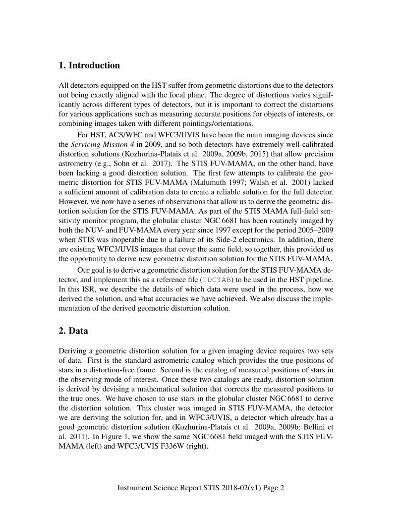
In Figure 5, we plot the residuals (observed−true positions) of the calibrationsources when our geometric distortion solution is applied. For comparison, we alsoshow the residuals without any correction – these are the original δx and δy used in theinitial step (1) above. The rms of δx and δy for the gray dots in Figure 5 are 1.10 and1.16 pixels, respectively, equivalent to 27.2 and 28.7 mas. With the geometric distortionsolution applied (red dots), these become 0.16 pix or 4.0 mas in each coordinate. Thisrepresents the precision of our geometric distortion solution.
4. Implementation and Tests
4.1 STIS Pipeline and IDCTAB
Images obtained with the STIS FUV-MAMA detector are geometrically corrected aspart of the calstis pipeline in the GEOCORR step (see STIS Data Handbook for details).The format of the IDCTAB, the reference file required in this step, is fully describedin Hack & Cox (2001). For consistency with older versions of IDCTAB as well asother STIS reference files, the same mean pixel scales (the SCALE paramter) as in theprevious IDCTAB (o8g1508eo idc.fits) were used. The new IDCTAB with pa-
Instrument Science Report STIS 2018-02(v1) Page 9

0 200 400 600 800 1000
0
200
400
600
800
1000
STIS FUV-MAMA
0 200 400 600 800 1000X (pixels)
0
200
400
600
800
1000
Y (
pixe
ls)
Figure 4.: Distortion map of the STIS FUV-MAMA. Black dots indicate the originalpositions, and red lines illustrate the direction and relative magnitude of the distortioncorrections. Red lines are magnified by a factor of 30 for visualization. The longest redline corresponds to ∼ 4 pixels in length.
rameters as listed in Table 3 is named 1771408ro idc.fits, and was implementedin the pipeline on July 7, 2017. Users that wish to manually apply the geometric dis-tortion corrections for STIS FUV-MAMA images are advised to follow the steps below.For this example, the flat-fielded image is named o1234567q flt.fits.
• Download the IDCTAB file from the following link:https://hst-crds.stsci.edu/browse/1771408ro_idc.fits
• Change the header parameters for keyword IDCTAB of the o1234567q flt.fits
Instrument Science Report STIS 2018-02(v1) Page 10
−4 −2 0 2 4
−4
−2
0
2
4
STIS FUV−MAMA
−4 −2 0 2 4δX (pixels)
−4
−2
0
2
4
δY (
pix
els
)
Figure 5.: Residual positions (i.e., observed−true) without the geometric distortioncorrection (gray dots), and with our new geometric distortion correction applied (reddots). Units are in STIS FUV-MAMA pixels. The average pixel scale for STIS FUV-MAMA is 0.0247 mas pix−1.
image to this downloaded file. If the downloaded IDCTAB file is located in thesame directory as the flat-fielded image, the header should look like:IDCTAB = ’./1771408ro idc.fits’
• Verify that the header keyword GEOCOR is set to PERFORM.
• Run calstis on the o1234567q flt.fits image. This will create thegeometrically-corrected image with the name o1234567q flt x2d.fits. In
Instrument Science Report STIS 2018-02(v1) Page 11

AstroConda, running calstis will look like below:
>>> import stistools>>> stistools.calstis.calstis(’o1234567q_flt.fits’)
4.2 Tests
We carried out a few tests with our newly derived geometric distortion solution as fol-lows. We first selected a random sample of our calibration data sets and corrected forthe geometric distortion solution as outlined in the previous section. We measured po-sitions of NGC 6681 stars in both the flt.fits (not corrected) and the x2d.fits(corrected) images. The standard astrometric catalog were transformed to these imagesusing the linear transformation solution of Equation 1. We then compared the trans-formed positions to the observed stars for assessments. Figure 6 shows the result of thisprocess for one example data set (o5in01tfq). We find that the transformed posi-tions are far better aligned with the geometrically-corrected images, indicating that thedistortion solutions are making significant improvements.
We also performed tests on data obtained with the F25QTZ and F25SRF2 aper-tures. We downloaded NGC 6681 calibration images obtained in these configurations,and rectified these images using the new distortion solution. We then repeated the pro-cess described above to calculate the residuals (transformed−observed positions) foreach detected star. Figure 7 shows the same 2-d residuals as shown in Figure 5, but forF25QTZ and F25SRF2 data sets. The rms of residuals is ∼ 0.18 pix in each coordi-nate, comparable to that of MIRCUV data. We conclude that our geometric distortionsolution derived using MIRCUV data improves both MIRCUV and MIRFUV data to asimilar precision level.
AcknowledgementsThe author would like to specially thank Andrea Bellini and Vera Kozhurina-Platais fortheir advice in various stages of this work.
Change History for STIS ISR 2018-XXVersion 1: Monday 16th April, 2018- Original Document
ReferencesBellini, A., Anderson, J., & Bedin, L. R., 2011, PASP, 123, 622Hack, W., & Cox, C., 2000, ACS ISR 2000-11Hack, W., & Cox, C., 2001, ACS ISR 2001-008Kozhurina-Platais, V., et al., 2009a, WFC3 ISR 2009-33Kozhurina-Platais, V., et al., 2009b, WFC3 ISR 2009-34
Instrument Science Report STIS 2018-02(v1) Page 12

Kozhurina-Platais, V., et al., 2015, ACS ISR 15-06Malumuth, E., 1997, STIS FUV-MAMA Geometric Distortion.
STIS Post Launch Quick Look Analysis Report No. 41. STIS IDT, Greenbelt.Piotto, G., Milone, A. P., Bedin, L. R., et al. 2015, AJ, 149, 91Walsh, J. R., Goudfrooij, P., & Malumuth, E. STIS ISR 2001-02
Instrument Science Report STIS 2018-02(v1) Page 13

(a) Without geometric distortion correction.
(b) With geometric distortion correction.
Figure 6.: Portion of the NGC 6681 field with stars circled in red. The top imageshows the non-corrected o5in01tfq flt.fits, and the bottom image shows thegeometrically-corrected o5in01tfq flt x2d.fits. The red circles correspond tothe standard astrometric catalog positions transformed to the individual images. Eachimage has a size of 350× 230 pixel2.
Instrument Science Report STIS 2018-02(v1) Page 14

−4 −2 0 2 4
−4
−2
0
2
4
STIS FUV−MAMA F25QTZ TEST
−4 −2 0 2 4δX (pixels)
−4
−2
0
2
4
δY (
pix
els
)
(a) Test on F25QTZ data sets.
−4 −2 0 2 4
−4
−2
0
2
4
STIS FUV−MAMA F25SRF2 TEST
−4 −2 0 2 4δX (pixels)
−4
−2
0
2
4δY
(pix
els
)
(b) Test on F25SRF2 data sets.
Figure 7.: Same as in Figure 5, but for F25QTZ (left) and F25SRF2 (right) data sets.The residuals after correction are plotted in blue (instead of red).
Instrument Science Report STIS 2018-02(v1) Page 15