a new geodetic network design for hydro power plant · ts09i - engineering surveying, 5876 joël...
TRANSCRIPT

TS09I - Engineering Surveying, 5876 Joël VAN CRANENBROECK, Andrey BALAN and Marco DI MAURO A New Geodetic Network Design for Hydro Power Plant FIG Working Week 2012 Knowing to manage the territory, protect the environment, evaluate the cultural heritage Rome, Italy, 6-10 May 2012
1/1
A New Geodetic Network Design for Hydro Power Plant
Joël VAN CRANENBROECK, Belgium Andrey BALAN, Ukraine Marco DI MAURO, Italy
Key words: Structural Health Analysis, GLONASS, GPS, Centralized Processing, RTK, Total Stations, Inclinometers, Least Squares Adjustment, Automatic Target Recognition, Geodetic Monitoring. SUMMARY The technical field of structural monitoring has made major progress in the recent years. New developments were driven by the need to keep engineering infrastructures in service beyond their expected lifetime due to limited funds for their replacement or because major modifications (like the change of turbines for increasing the power capacity) will impact. The environment can also change (seismic events, tsunami) and hurt the infrastructures especially if the design or the code of construction has been under evaluated. Actually the term “Structural Health Monitoring” is more and more often used and refers to methods witch access the health status and safety of a structure and make estimation of its remaining lifetime. However, structures can only be kept in service if they do not put the safety of the users at risk. Critical parts of a structure as well as global behaviour have to be monitored in continuous intervals (frequency) with accuracy generally 3 to 10 times greater than the expected maximum deflection. The aim of deformation analysis has shifted and nowadays experts are not even looking if critical points of a structure have moved (and by the way due to thermal loads and the modification of water levels every structure such Hydro Power Plant is moving) but well if some patterns have significantly changed to alert and lead more investigations... With highest resolution and highest recording rate of today's instruments the small deformations caused by the daily temperature changes, water levels etc. can be observed. The paper review new geodetic network design for monitoring Hydro Power Plant introducing a change in paradigm if we consider the traditional method developed originally in Switzerland years ago and still considered as best practice while actually outdated by the new technologies.

TS09I - Engineering Surveying, 5876 Joël VAN CRANENBROECK, Andrey BALAN and Marco DI MAURO A New Geodetic Network Design for Hydro Power Plant FIG Working Week 2012 Knowing to manage the territory, protect the environment, evaluate the cultural heritage Rome, Italy, 6-10 May 2012
2/2
A New Geodetic Network Design for Hydro Power Plant
Joël VAN CRANENBROECK, Belgium Andrey BALAN, Ukraine Marco DI MAURO, Italy
1. FACING NEW CHALLENGE Engineering companies and contractors are facing challenges never experienced before. They are being charged with – and being held liable for – the health of the structures they create and maintain. To surmount these challenges, engineers need to be able to measure structural movements to millimeter level accuracy. Accurate and timely information on the status of a structure is highly valuable to engineers. It enables them to compare the real-world behavior of a structure against the design and theoretical models. When empowered by such data, engineers can effectively and cost efficiently measure and maintain the health of vital infrastructure. The ability to detect and react to potential problems before they develop helps in the reduction of insurance costs and the prevention of catastrophic failures that may results in injury, death or significant financial loss. A structural monitoring system will help reduce both the current and long term maintenance cost associated with structural movement and will reduces risks, as data analysis can be used to aid the understanding of current and future implications of structural movements. Safety and structural integrity concerns can be minimized. Potential problems can be detected and rectified before a critical situation develops. Considering the return on investment that the financial organizations are looking on such infrastructures, a monitoring system is therefore mandatory to guarantee the proper realization of the financial plan associated. 2. FROM AUTOMATIC SURVEYING TO PRECISE CONTINUOUS
MONITORING Based on surveying sensors like GNSS receivers and Automatic Total Stations, Geodetic Monitoring solutions are integrating also wireless communication tools, acquisition software’s, PC servers, accessories, power supply, solar panels, weather station, warning sensors, web interfaces and analysis to become complex systems. And if the engineers today are considering often the surveying instrumentation just like “sensors” to be plugged and connected to even their real time analysis software’s, they shouldn’t forget that the key for succeeding in their monitoring projects is first to consider instrumentation and equipments that can deliver high accurate and reliable measurements 24
TS09I - Engineering Surveying, 5876 Joël VAN CRANENBROECK, Andrey BALAN and Marco DI MAURO A New Geodetic Network Design for Hydro Power Plant FIG Working Week 2012 Knowing to manage the territory, protect the environment, evaluate the cultural heritage Rome, Italy, 6-10 May 2012
3/3
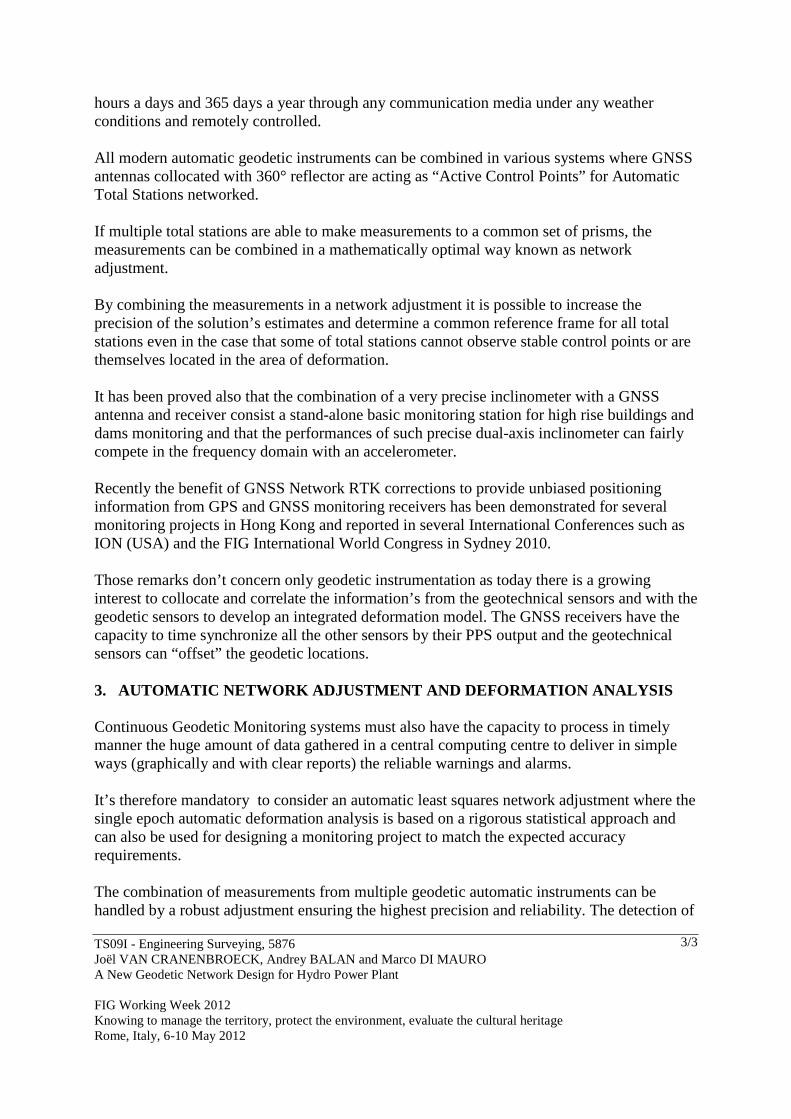
hours a days and 365 days a year through any communication media under any weather conditions and remotely controlled. All modern automatic geodetic instruments can be combined in various systems where GNSS antennas collocated with 360° reflector are acting as “Active Control Points” for Automatic Total Stations networked. If multiple total stations are able to make measurements to a common set of prisms, the measurements can be combined in a mathematically optimal way known as network adjustment. By combining the measurements in a network adjustment it is possible to increase the precision of the solution’s estimates and determine a common reference frame for all total stations even in the case that some of total stations cannot observe stable control points or are themselves located in the area of deformation. It has been proved also that the combination of a very precise inclinometer with a GNSS antenna and receiver consist a stand-alone basic monitoring station for high rise buildings and dams monitoring and that the performances of such precise dual-axis inclinometer can fairly compete in the frequency domain with an accelerometer. Recently the benefit of GNSS Network RTK corrections to provide unbiased positioning information from GPS and GNSS monitoring receivers has been demonstrated for several monitoring projects in Hong Kong and reported in several International Conferences such as ION (USA) and the FIG International World Congress in Sydney 2010. Those remarks don’t concern only geodetic instrumentation as today there is a growing interest to collocate and correlate the information’s from the geotechnical sensors and with the geodetic sensors to develop an integrated deformation model. The GNSS receivers have the capacity to time synchronize all the other sensors by their PPS output and the geotechnical sensors can “offset” the geodetic locations. 3. AUTOMATIC NETWORK ADJUSTMENT AND DEFORMATION ANALYS IS Continuous Geodetic Monitoring systems must also have the capacity to process in timely manner the huge amount of data gathered in a central computing centre to deliver in simple ways (graphically and with clear reports) the reliable warnings and alarms. It’s therefore mandatory to consider an automatic least squares network adjustment where the single epoch automatic deformation analysis is based on a rigorous statistical approach and can also be used for designing a monitoring project to match the expected accuracy requirements. The combination of measurements from multiple geodetic automatic instruments can be handled by a robust adjustment ensuring the highest precision and reliability. The detection of
TS09I - Engineering Surveying, 5876 Joël VAN CRANENBROECK, Andrey BALAN and Marco DI MAURO A New Geodetic Network Design for Hydro Power Plant FIG Working Week 2012 Knowing to manage the territory, protect the environment, evaluate the cultural heritage Rome, Italy, 6-10 May 2012
4/4
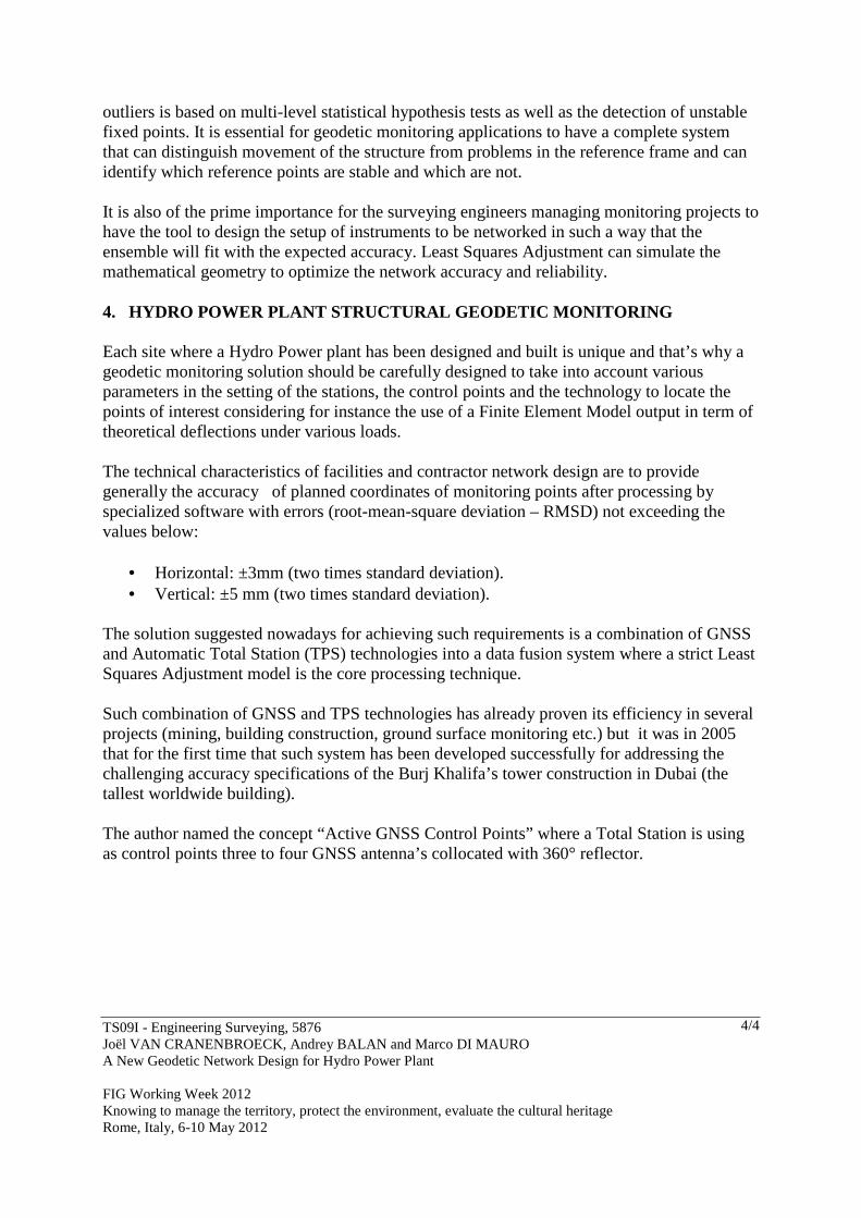
outliers is based on multi-level statistical hypothesis tests as well as the detection of unstable fixed points. It is essential for geodetic monitoring applications to have a complete system that can distinguish movement of the structure from problems in the reference frame and can identify which reference points are stable and which are not. It is also of the prime importance for the surveying engineers managing monitoring projects to have the tool to design the setup of instruments to be networked in such a way that the ensemble will fit with the expected accuracy. Least Squares Adjustment can simulate the mathematical geometry to optimize the network accuracy and reliability. 4. HYDRO POWER PLANT STRUCTURAL GEODETIC MONITORING Each site where a Hydro Power plant has been designed and built is unique and that’s why a geodetic monitoring solution should be carefully designed to take into account various parameters in the setting of the stations, the control points and the technology to locate the points of interest considering for instance the use of a Finite Element Model output in term of theoretical deflections under various loads. The technical characteristics of facilities and contractor network design are to provide generally the accuracy of planned coordinates of monitoring points after processing by specialized software with errors (root-mean-square deviation – RMSD) not exceeding the values below:
• Horizontal: ±3mm (two times standard deviation). • Vertical: ±5 mm (two times standard deviation).
The solution suggested nowadays for achieving such requirements is a combination of GNSS and Automatic Total Station (TPS) technologies into a data fusion system where a strict Least Squares Adjustment model is the core processing technique. Such combination of GNSS and TPS technologies has already proven its efficiency in several projects (mining, building construction, ground surface monitoring etc.) but it was in 2005 that for the first time that such system has been developed successfully for addressing the challenging accuracy specifications of the Burj Khalifa’s tower construction in Dubai (the tallest worldwide building). The author named the concept “Active GNSS Control Points” where a Total Station is using as control points three to four GNSS antenna’s collocated with 360° reflector.

TS09I - Engineering Surveying, 5876 Joël VAN CRANENBROECK, Andrey BALAN and Marco DI MAURO A New Geodetic Network Design for Hydro Power Plant FIG Working Week 2012 Knowing to manage the territory, protect the environment, evaluate the cultural heritage Rome, Italy, 6-10 May 2012
5/5
Fig 1 : For the Burj Khalifa, the Total Station was even considered as not referenced to the gravity vertical and due to building motion and vibration, the compensator has been switched off. The processing was purely in a 3D
frame. Total deflection of the tower was about 4 mm from the design.
In the new design for monitoring Hydropower Dams, all the GNSS Control Points antenna’s would be collocated with a 360° reflector that all Total Stations would be able to measure providing an unique combination of sensors.
Part of the new design is based on the fact that Automatic Total Stations will also measure the directions Hz, Vz and the slope distances to the 360° reflector collocated with the GNSS antenna’s of the Control Points such as illustrated here:
Fig 2: proposed new design

TS09I - Engineering Surveying, 5876 Joël VAN CRANENBROECK, Andrey BALAN and Marco DI MAURO A New Geodetic Network Design for Hydro Power Plant FIG Working Week 2012 Knowing to manage the territory, protect the environment, evaluate the cultural heritage Rome, Italy, 6-10 May 2012
6/6
GNSS data can be processed in either real time (at rates up to 20 Hz) or in post processed mode. Real time processing enables movements to be detected very rapidly and on average has a one sigma accuracy of less than a centimetre for baselines up to 3km (Brown et al. 2006). The accuracy of real time processing is related to the geometry of the satellite constellation (the number, azimuth and elevation of the satellites that are tracked) at the time of measurement. The GPS satellites travel with a speed of 4 km/s and orbit the earth approximately every 12 hours. Hence, the satellite geometry is constantly changing and there are times of the day when it is good and other times when it is poor, especially if the sky view is restricted. In times of poor satellite geometry it may not be possible to compute a high accuracy (ambiguity fixed) solution and the reliability of the solution (the probability that the ambiguities are resolved correctly) will be lower. If high accuracy and reliability is critical, a better option is to collect data over a defined period (e.g. 10 minutes, 1 hour, and 24 hours) and post process. In post processing more data can be used to estimate the parameters (coordinates, ambiguities, error models) mitigating short term problems due to poor satellite geometry and resulting in a more reliable and accurate solution. Usually the result of post processing is a single high accuracy coordinate, essentially an average over the time period. Long data periods (e.g. one hour or more) also enable additional parameters to be estimated to account for atmospheric (troposphere) influences, which are strongly correlated with the station height, further improving the accuracy. As an additional step, a median can be computed from the post processing results over a longer time period in order to avoid any potential problems due to outliers. Post processing combined with a median calculation is a very stable and accurate method for computing and updating reference coordinates using GNSS data. The downside of this approach is that if a sudden movement occurs, it will take some time for the system to react. The solution is then to compute multiple position estimates: a rapid estimate using real time data or a short post processing interval to detect sudden movements to provide alarms to the operator; and a slower estimate using a longer post processing interval to correct for the gradual movements of the pillars. The standard mode of precise differential positioning is for one reference receiver to be located at a reference station whose coordinates are known, while the second receiver's coordinates are determined relative to this reference receiver. The use of carrier phase data in real-time, single baseline mode (one reference station and one rover or user receiver’s coordinates to be determined in a relative sense) – also known as “single-base” mode – is now common place. These systems are also referred to as RTK systems (“real-time-kinematic”), and make feasible the use of GPS/GNSS-RTK for many time-critical applications such as engineering surveying, GPS/GNSS-guided earthworks/excavations, machine control and structural monitoring applications.

TS09I - Engineering Surveying, 5876 Joël VAN CRANENBROECK, Andrey BALAN and Marco DI MAURO A New Geodetic Network Design for Hydro Power Plant FIG Working Week 2012 Knowing to manage the territory, protect the environment, evaluate the cultural heritage Rome, Italy, 6-10 May 2012
7/7
Over the last decade and a half the use of GPS (and now GNSS) for structural monitoring, of dams, bridges, buildings and other civil structures, has grown considerably (see Ogaja et al., 2007, for a recent review), and nowadays the GNSS-RTK technique is widely used around the world. Such systems output continuous streams of coordinate results (or time series). The dynamics of the structure typically defines the nature of the coordinate analysis. For example, if a structure vibrates or deflects due to wind or surface loading the time series analysis is conducted in the frequency domain (see, e.g., Li et al., 2007), otherwise standard geodetic deformation monitoring techniques based on advanced network least squares analysis are used (Ogaja et al., 2007).
Fig 3: Leica GNSS Spider Positioning is centralized RTK processing “multi-baseline” software. The interest of having at least two or more GNSS Reference Stations in a monitoring project is that all GNSS Reference Stations can also check each other in a relative mode to detect eventual movements that would be disastrous on the GNSS Monitoring points. Last but not least any other GNSS Reference Station is also part of backing-up the system. This is clearly an “Integrity Control” solution. The other significant advantage of having a “centralized” processing approach is that for the processing of the various baselines, the GNSS Reference Station can be selected freely and all combination of baselines can be considered. Even more interesting is that the position between the GNSS Control Points or monitoring stations can also be processed using different combination and mode. Each baseline for instance can be processed in dual frequency (L1 and L2) mode but also in the single frequency mode (L1) and considering only GPS or GPS and GLONASS. The resolution of the ambiguities has been also extended with the “Quasi-Static” initialisation method where the variance of the GNSS monitoring station estimated a priori is considered for speeding up the initialisation time to fix.

TS09I - Engineering Surveying, 5876 Joël VAN CRANENBROECK, Andrey BALAN and Marco DI MAURO A New Geodetic Network Design for Hydro Power Plant FIG Working Week 2012 Knowing to manage the territory, protect the environment, evaluate the cultural heritage Rome, Italy, 6-10 May 2012
8/8
5. GNSS POST-PROCESSING AND TOTAL STATIONS FUSION DESIGN If GNSS positioning technology allows various mode of processing such as “Real Time Kinematic” only the “Post-Processing or “Near Real Time” mode is able to combine closely and at a compatible accuracy the measurements GNSS receivers with those obtained by the Total Stations an integrated rigorous Least-Squares Adjustment model. The final design the author would suggest is then the following:
Fig 5 : Author’s final design proposal considering two GNSS Reference Stations surrounding the Hydropower Dam’ sites to be integrated with the Total Stations measurements by using 360° reflectors collocated with the
GNSS Antenna’s Control Points into a global Least Squares Adjustment model.
To summarize the value proposition to consider more than only one GNSS Reference Station in that model:
• The computation of single baselines from the GNSS Reference Station to the GNSS Control Points cannot be controlled (no redundancy) independently and will depend entirely of the performances of that GNSS Reference Station. Simply said, there is no”back-up” no double check. Karl Friedrich Gauss favourite’s sentence was “Eine messung is keine messung!” that could be translated by “One measurement is not a measurement!”
• One can argue that already in the design, the Total Station’s measurements can control the performances of the GNSS processing (comparing the directions Hz, Vz and the slope distances Ds). But that will not bring enough contrast in the solution to clearly indentify possible “outliers” and much more important to

TS09I - Engineering Surveying, 5876 Joël VAN CRANENBROECK, Andrey BALAN and Marco DI MAURO A New Geodetic Network Design for Hydro Power Plant FIG Working Week 2012 Knowing to manage the territory, protect the environment, evaluate the cultural heritage Rome, Italy, 6-10 May 2012
9/9
discriminate if it is a movement induced by the deformation of the structure or simply by the noise level of the solution.
• The Total Station measurements will also be affected by the refraction caused by the water surface and the high humidity level. It’s suggesting to install meteo sensor outside the hut protecting the Total Station to mitigate some part of the refraction influence (using the well known Barrel and Sears model) but comparing the distance from the GNSS Receivers and the distance deduced from the solution obtained from the Total Station will “scale-up” the distance biased by the remaining un-modelled effects of the refraction. Therefore the following design will allow experts to study and derive the correct refraction model applicable in such very local case and tune the network processing accordingly the results.
• We cannot pretend that the areas where Hydro Power dams are located will not be subject to deformation as well. There is a large interest today in the “reservoir induced earthquake”. In numerous parts of the world today, including some of the most highly developed countries, many dam designers and operators have tended to close their eyes to the engineering problems posed by reservoir-induced earthquakes. Virtually every careful study has concluded that there is indeed a cause-and-effect relationship between some earthquakes and some reservoirs, and two dams (Koyna, India, and Hsinfengkiang, China) have in fact come uncomfortably close to disastrous failure during such events. Furthermore, it is precisely in the regions of low natural seismicity where the major existing problems lie, because in areas of high seismicity dams are usually designed for substantial earthquake resistance anyway. For those reasons, the author is advocating to have one of the GNSS Reference Station as “Master” Reference Station to be part of a Regional Integrity monitoring program that would ideally be lead by the institution that has such positioning infrastructure under his responsibility.
We would like to stress that for “safety” driven projects, the results provided by a Deformation Permanent Monitoring System must be un-ambiguous and definitively not subject to contestation or justification by “force majeure” elements. 6. PROCESSING WORKFLOW All the data streams from the GNSS Receivers are gathering in real time mode into software such Leica GNSS Spider and share with different modules. Leica GNSS Spider Site Server is managing the incoming observation streams to archive and convert the data into the RINEX file format for quality check, transfer to the Integrity Monitoring processing centre and used for GNSS Post-Processing sequences.

TS09I - Engineering Surveying, 5876 Joël VAN CRANENBROECK, Andrey BALAN and Marco DI MAURO A New Geodetic Network Design for Hydro Power Plant FIG Working Week 2012 Knowing to manage the territory, protect the environment, evaluate the cultural heritage Rome, Italy, 6-10 May 2012
10/10
Fig 6: Workflow processing for GNSS RTK-Processing. The same baseline can be processed in parallel using different parameters.
At an interval defined after the pre-run analysis of the network, all the data streams from the GNSS receivers are converted into the standardized data exchange format RINEX. As soon those RINEX files will be produced (every 10 minutes, 1 hour, 6 hour, … daily), the software will automatically post-processed the various combinations of baselines defined and will write the results into the SQL database for being pulled out by the monitoring software and combined automatically into a rigorous Least Squares Adjustment with the Automatic Total Stations measurements.
Fig 9: Workflow GNSS Post-Processing with integration of Total Station measurements into a global model of Adjustment.
The software is also driving the geodetic sensors such as GNSS receivers and Total Stations and processing - after reduction - the observations separately to provide estimated coordinates, while the automatic adjustment module is integrating all the observations into a global model.
TS09I - Engineering Surveying, 5876 Joël VAN CRANENBROECK, Andrey BALAN and Marco DI MAURO A New Geodetic Network Design for Hydro Power Plant FIG Working Week 2012 Knowing to manage the territory, protect the environment, evaluate the cultural heritage Rome, Italy, 6-10 May 2012
11/11
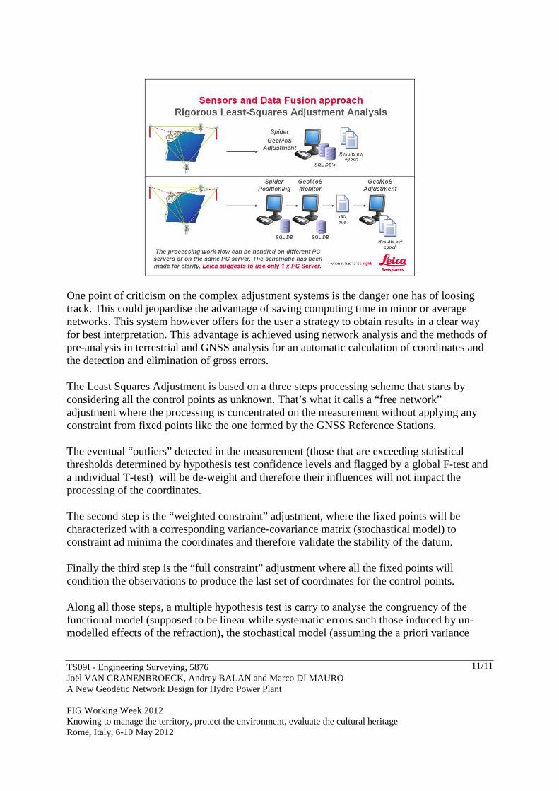
One point of criticism on the complex adjustment systems is the danger one has of loosing track. This could jeopardise the advantage of saving computing time in minor or average networks. This system however offers for the user a strategy to obtain results in a clear way for best interpretation. This advantage is achieved using network analysis and the methods of pre-analysis in terrestrial and GNSS analysis for an automatic calculation of coordinates and the detection and elimination of gross errors. The Least Squares Adjustment is based on a three steps processing scheme that starts by considering all the control points as unknown. That’s what it calls a “free network” adjustment where the processing is concentrated on the measurement without applying any constraint from fixed points like the one formed by the GNSS Reference Stations. The eventual “outliers” detected in the measurement (those that are exceeding statistical thresholds determined by hypothesis test confidence levels and flagged by a global F-test and a individual T-test) will be de-weight and therefore their influences will not impact the processing of the coordinates. The second step is the “weighted constraint” adjustment, where the fixed points will be characterized with a corresponding variance-covariance matrix (stochastical model) to constraint ad minima the coordinates and therefore validate the stability of the datum. Finally the third step is the “full constraint” adjustment where all the fixed points will condition the observations to produce the last set of coordinates for the control points. Along all those steps, a multiple hypothesis test is carry to analyse the congruency of the functional model (supposed to be linear while systematic errors such those induced by un-modelled effects of the refraction), the stochastical model (assuming the a priori variance

TS09I - Engineering Surveying, 5876 Joël VAN CRANENBROECK, Andrey BALAN and Marco DI MAURO A New Geodetic Network Design for Hydro Power Plant FIG Working Week 2012 Knowing to manage the territory, protect the environment, evaluate the cultural heritage Rome, Italy, 6-10 May 2012
12/12
factor and the covariance are reflecting the effective accuracy of the observations) and the observations.
Fig 10: The automatic adjustment module is processing a rigorous Least Squares Adjustment in several steps to insure best linear unbiased estimators for all the control points.
The automatic deformation analysis is based on epoch-by-epoch scheme by considering the initial set of coordinates as the reference epoch. Each adjustment is producing a coordinates vector and its corresponding variance-covariance matrix with the a-posteriori variance factor that are first aligned using a similarity transformation type often named “S-Transformation” from which the residuals are analysed using hypothesis tests to check the “normality” of the corresponding distribution associated at each epoch.
Fig 11: The automatic adjustment module is able to check if control points have moved as well as if fixed points (GNSS Reference Stations) are still stable.

TS09I - Engineering Surveying, 5876 Joël VAN CRANENBROECK, Andrey BALAN and Marco DI MAURO A New Geodetic Network Design for Hydro Power Plant FIG Working Week 2012 Knowing to manage the territory, protect the environment, evaluate the cultural heritage Rome, Italy, 6-10 May 2012
13/13
7. FEASIBILITY STUDY OF A CASE DESIGN We will examine first the situation where we could deploy three GNSS Reference Stations, then we will decrease to two GNSS Reference Stations and we will examine at the end what would be the performances with only one GNSS Reference Stations.
Fig 12: Design with three GNSS Reference Stations – Accuracy is meeting and exceeding the specifications.
Fig 13: Design with two GNSS Reference Stations – Accuracy is meeting and exceeding the specifications. Difference with three GNSS Reference Stations is only about 0.2 mm!
TS09I - Engineering Surveying, 5876 Joël VAN CRANENBROECK, Andrey BALAN and Marco DI MAURO A New Geodetic Network Design for Hydro Power Plant FIG Working Week 2012 Knowing to manage the territory, protect the environment, evaluate the cultural heritage Rome, Italy, 6-10 May 2012
14/14
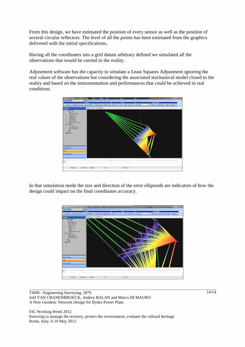
From this design, we have estimated the position of every sensor as well as the position of several circular reflectors. The level of all the points has been estimated from the graphics delivered with the initial specifications. Having all the coordinates into a grid datum arbitrary defined we simulated all the observations that would be carried in the reality. Adjustment software has the capacity to simulate a Least Squares Adjustment ignoring the real values of the observations but considering the associated stochastical model closed to the reality and based on the instrumentation and performances that could be achieved in real conditions.
In that simulation mode the size and direction of the error ellipsoids are indicators of how the design could impact on the final coordinates accuracy.

TS09I - Engineering Surveying, 5876 Joël VAN CRANENBROECK, Andrey BALAN and Marco DI MAURO A New Geodetic Network Design for Hydro Power Plant FIG Working Week 2012 Knowing to manage the territory, protect the environment, evaluate the cultural heritage Rome, Italy, 6-10 May 2012
15/15
We can deduce from their numerical values that the results will be precise and homogeneous indicating that the proposed design based on three GNSS Reference Stations and the combination of GNSS Control Points collocated 360° reflector with the Total Stations meets and exceeds the accuracy requirements of the tender specifications. The output of the simulation gave us also for each observation an estimate about the capacity each of them will have to detect a deformation of the related point. The average standard deviation for the monitored object points in plane is about 1mm for the height 1.4 mm. This allows detecting movements – deformation in the engineering object better 2mm.The local redundancy is between 30 and 70 % and allows a reliable detection of deformations. Finally the selected network geometry and defined instruments (GNSS and Total Station type) allows achieving a real reliable network for a long term monitoring.
3 x GNSS + 2 x TPS
Pt Id Ellipse Or. A B Mx Mx RMS XY RMS Z ∆∆∆∆ RMS XY ∆∆∆∆ RMS Z C1 207.4 0.9 0.8 0.8 0.9 1.2 1.8 0.0 0.1 C2 217.4 0.8 0.8 0.8 0.8 1.1 1.7
2 x GNSS + 2 x TPS
Pt Id Ellipse Or. A B Mx Mx RMS XY RMS Z ∆∆∆∆ RMS XY ∆∆∆∆ RMS Z C1 207.9 0.9 0.8 0.8 0.9 1.2 1.8 0.0 0.1 C2 217.8 0.8 0.8 0.8 0.8 1.2 1.8
1 x GNSS + 1 x TPS
Pt Id Ellipse Or. A B Mx Mx RMS XY RMS Z ∆∆∆∆ RMS XY ∆∆∆∆ RMS Z C1 250.0 1.1 1.0 1.1 1.1 1.5 2.4 0.3 0.6 C2 218.2 0.9 0.8 0.8 0.9 1.2 1.8
2 x GNSS
Pt Id Ellipse Or. A B Mx Mx RMS XY RMS Z ∆∆∆∆ RMS XY ∆∆∆∆ RMS Z C1 200.0 2.2 2.2 2.2 2.2 3.2 7.1 2.0 5.3 C2 218.3 0.9 0.8 0.8 0.9 1.2 1.8
1 x GNSS
Pt Id Ellipse Or. A B Mx Mx RMS XY RMS Z ∆∆∆∆ RMS XY ∆∆∆∆ RMS Z C1 200.0 3.2 3.2 3.2 3.2 4.5 10.0 3.3 8.2 C2 218.3 0.9 0.8 0.8 0.9 1.2 1.8

TS09I - Engineering Surveying, 5876 Joël VAN CRANENBROECK, Andrey BALAN and Marco DI MAURO A New Geodetic Network Design for Hydro Power Plant FIG Working Week 2012 Knowing to manage the territory, protect the environment, evaluate the cultural heritage Rome, Italy, 6-10 May 2012
16/16
In that table we have put for that given situational design the different values for the RMS xy and RMS z as performance criteria. The point C1 is compared with the point C2 (used as a reference and processed with 3 x GNSS + 2 x TPS). So we can see that a network based on 2 x GNSS + 2 x TPS is offering theoretically the same performance level in term of point’s accuracy than the 3 x GNSS + 2 x TPS. Even in case of failure the situation 1 x GNSS + 1 x TPS is acceptable. At the end, the proposed instrument and software for a typical design guarantees to meet the specification in term of accuracy at 2 σ level. In that new design proposal for a Deformation Permanent Monitoring System, the author has described the best possible way to engage the most advanced scalable and flexible geodetic monitoring solution for the various sites where again safety is the prime focus. ACKNOWLEDGMENTS The author would like first to express his special thanks to Dr Ivo MILEV who contributed to the simulation of the various design and also to the people who has adopted and are supporting Leica Geosystems geodetic monitoring solutions. It is all the time and for every project a team work to find the best combination of instruments, processing software’s to design the most appropriated solutions for standard, critical or challenging projects. The author knows also that in geodetic monitoring there is simply no “traditional” project and for the case of the Hydro Power plant where each site is unique that sentence is particularly true.

TS09I - Engineering Surveying, 5876 Joël VAN CRANENBROECK, Andrey BALAN and Marco DI MAURO A New Geodetic Network Design for Hydro Power Plant FIG Working Week 2012 Knowing to manage the territory, protect the environment, evaluate the cultural heritage Rome, Italy, 6-10 May 2012
17/17
REFERENCES [1] Brown, N., Kaloustian, S., Roeckle M. (2008). Monitoring of Open Pit Mines using Combined GNSS Satellite Receivers and Robotic Total Stations. [2] Brown, N., Troyer Lienhart, Zelzer, O., Van Cranenbroeck, J. (2006). Advanced in RTK and Post Processed Monitoring with Single Frequency GPS. Journal of Global Positioning Systems, Vol 5, N°. 1-2:145-151 [3] Van Cranenbroeck, J., Brown N. (2004). Networking Motorized Total Stations and GPS Receivers for Deformation Measurement. FIG Working Week, Athens, Greece. [4] Zog, H-M., Lienhart, W., Nindl D. (2009). Leica TS30 – The Art of Achieving Highest Accuracy and Performance. [5] Van Cranenbroeck. J., Aschroft. N. (2007). Single to Multi Frequency GNSS Signal Processing Solutions for Engineering Structure Monitoring Applications. The International Global Navigation Satellites Systems Society Inc. (IGNSS) IGNSS2007 Symposium – The University of New South Wales, Sydney Australia. [6] Van Cranenbroeck. J., Lui. V., Wu. X. (2007). ICE 5th International Conference Bridge – Beijing, supported by the FIG Commission 6 WG4. [7] Van Cranenbroeck. J. (2007). Continuous Beam Deflection Monitoring Using Precise Inclinometers. Strategic Integration of Surveying Services FIG Working Week, Hong Kong SAR, China. [8] Van Cranenbroeck, J. (2007). An Integrated Geodetic Measurement and Analysis System for Large Dams Monitoring. Hydropower & Dams issue 2 : INSTRUMENTATION SYSTEMS FOCUS. [9] Van Cranenbroeck, J. (2006). Core Wall Survey Control System. Opening paper – 3rd IAG Symposium on Geodesy for Geotechnical and Structural Engineering, 12th FIG Symposium on Deformation Measurement. [10] Lienhart, W. (2007). Analysis of Inhomogeneous Structural Monitoring Data. Engineering Geodesy – TU Graz, Austria. Shaker Verlag

TS09I - Engineering Surveying, 5876 Joël VAN CRANENBROECK, Andrey BALAN and Marco DI MAURO A New Geodetic Network Design for Hydro Power Plant FIG Working Week 2012 Knowing to manage the territory, protect the environment, evaluate the cultural heritage Rome, Italy, 6-10 May 2012
18/18
BIOGRAPHICAL NOTES Joël van Cranenbroeck is currently Business Technology Manager at the New Business Division of Leica Geosystems AG, Heerbrugg, Switzerland. He led the development of hardware and software solutions for GNSS Network-RTK since 2001 and made significant contributions in geodetic monitoring development and applications such as the method for aligning high rise structures (such as the Burj Dubai). Joel is Chair of Working Group 6.2 in FIG Commission 6, was awarded in 2009 the title of Honored Lecturer of the Siberian State Academy of Geodesy in Novosibirsk, and is senior scientist consultant for two universities in Belgium. He designed numerous projects for structural monitoring applications such as bridges, dams, tunnels, etc. He worked at the Belgian Cadastre organization, at the Geodetic Department of the Belgian National Geographical Institute and in Star Informatic – a GIS software based Belgian company – before he joined Van Hopplynus, the Leica Geosystems exclusive representative in Belgium in 1993 as product specialist in GPS, GIS, Engineering and Industrial applications. Andrey Balan is currently Managing Director of Leica Geosystems AG’s Representative office in Ukraine. He led service support of Leica products and made significant contributions for first Service Centre of Leica Geosystems AG in Ukraine and Regional GNSS RTK -Network of Continuous Operating Reference Stations in Kharkov region. At the moment he leads as a project director the WB project that concerns Supplying and Installation of Internal Permanent Deformation Monitoring System for 4 Hydro Power Plants on the Dnipro and Dniester rivers. Marco Di Mauro is Competence Manager for Infrastructure working for IMoSS AG a company part of the Hexagon Group and reporting to the New Business Division of Leica Geosystems AG. Involved in monitoring and early warning systems since years starting with geotechnical and ending up with geodetic instrumentation, Marco contributed as inventor (European patent) of a new profile measurement system based on electrolytic tilt sensor. He has been for several years project manager for AGISCO srl, Italy and recently for Leica Geosystems AG, Switzerland CONTACTS Joël van Cranenbroeck Leica Geosystems AG Heinrich Wild Strasse CH-9435 HEERBRUGG SWITZERLAND Tel. +32 474 98 61 93 Fax +32 81 41 26 02 Email: [email protected] Web site: www.leica-geosystems.com

TS09I - Engineering Surveying, 5876 Joël VAN CRANENBROECK, Andrey BALAN and Marco DI MAURO A New Geodetic Network Design for Hydro Power Plant FIG Working Week 2012 Knowing to manage the territory, protect the environment, evaluate the cultural heritage Rome, Italy, 6-10 May 2012
19/19
Andrey Balan Leica Geosystems AG (Representative Office) 69V Frunze street 04080 KYIV UKRAINE Tel. +38 044 465 69 19 Mob +38 050 303 69 19 Email: [email protected] Web site: www.leica-geosystems.com Marco Di Mauro IMoSS AG Heinrich Wild Strasse CH-9435 HEERBRUGG SWITZERLAND Web site: www.leica-geosystems.com