a new design of processing element of fft using simulink
TRANSCRIPT

A New Design of Processing Element of FFT using Simulink
Abhinav Ranjan1, Dr. Shraddha Prasad2 1Research Scholar, Faculty of Science and Engineering, Jharkhand Rai University, Ranchi
2Associate Professor, Faculty of Science and Engineering, Jharkhand Rai University, Ranchi
Abstract
This paper presents a methodology for implementing FFT based algorithms on a field
programmable gate arrays (FPGA) using Xilinx System Generator (XSG) in Matlab
Simulink. The FFT are simulated using Matlab Simulink environment and System Generator,
a tool from Xilinx used for FPGA design. We present the idea of simulation of mathematical
model on mixed Hardware Description Language (HDL)-Simulink using Xilinx system
generator. Many applications that are FFT based or certain communication application
require mathematical modeling for their easy understanding and analysis. Due to the
complexity of pure HDL it is unable to simulate. Also it is expensive and time consuming
process.
HDL Coder generates movable and combined form of Verilog and VHDL code from
MATLAB functions, Simulink models and Stateflow charts. The HDL code which is
generated is used for FPGA programming or ASIC prototyping and design.
HDL Coder comes up with a workflow advisor that controls the programming of Xilinx
and Altera FPGAs. We can command HDL architecture and its implementation by
featuring its critical paths and by generating hardware resource utilization estimation.
HDL Coder comes up with recognizable outcome between Simulink model and the
generated Verilog and VHDL code by enabling code verification for high-integrity
applications attaching to DO-254 and other standards. DO-254 is a Design Assurance
Guidance for Airborne Electronic Hardware (AEH) and it provides guidance for design
assurance in airborne electronic hardware to ensure safe operation.
This paper presents the implementation of FFT algorithms that can compute fourier
transform of varied signals in real time for frequency analysis of signals on FPGAs.
Keywords
FPGA (Field programmable gate arrays), XSG (Xilinx System Generator), FFT (Fast Fourier
Transform), IFFT (Inverse Fast Fourier Transform), AEH (Airborne Electronic
Hardware), HDL (Hardware Description Language)
Journal of Information and Computational Science
Volume 10 Issue 9 - 2020
ISSN: 1548-7741
www.joics.org257

1. Introduction
This paper comes up with a new outlook towards the design and modeling of complex
mathematical model by applying mixed HDL platform of Simulink and Xilinx form of the
design architecture.
For multi-domain simulation and Model-Based Design, Matlab-Simulink is an environment
for resulting in dynamic and embedded systems. In this approach Matlab-Simulink comes up
with a high level development tool in the design process. Xilinx System Generator is a
system-level modeling tool from Xilinx that facilitates FPGA hardware design [4].
Simulink is a schematic diagram environment for multi-domain simulation and model-
Based Design. It holds up simulation, automatic code generation, and continuous test and
confirmation of embedded processes.
Simulink produces a graphical editor, specially made block libraries, and solvers for
modeling and simulating dynamic systems. It is integrated with MATLAB, enabling us
to include MATLAB algorithms into models and export simulation results to MATLAB
for further analysis. Simulink is universally used in control theory and digital signal
processing for multi-domain simulation and Model-Based Design [10].
2. Computation of FFT
The FFT computation takes three steps namely [2],
1. Previous Computation
The butterfly structure of the first stage takes the form of
𝐵41 = [𝑥]4×4 ∗ [𝑊4]4×4 … … … … … . (1)
2. Complex Multiplication
𝐶4 = [𝑊4]4×4 ∗ [𝐵41]4×4 … … … . . (2)
3. Post computation
The butterfly structure of the second stage takes the form of
𝐵42 = [𝑊4]4×4 ∗ [𝐶]4×4 … … … . . (3)
Based on the Equation (1) and (3) the operation performed on Previous and Post
computations are same. So, we can use a single Processing Element to perform these
Journal of Information and Computational Science
Volume 10 Issue 9 - 2020
ISSN: 1548-7741
www.joics.org258

computations. The ordering of input order is given in special order to the Processing
Element.
For 𝑛 = ⟨0, 1, 2, 3⟩, the Processing Element will take the input as
𝑥(1, 9, 13, 5),
𝑥(2, 10, 14, 6),
𝑥(3, 11, 15, 7),
𝑥(4, 12, 16, 8).
respectively, and performs the first step i.e., Previous computation as shown in the Fig. A
FIGURE A : Modified Radix−42 butterfly structure
Then, this Fig. A can be remodeled in Simulink and will be considered as the proposed
Processing Element (Fig. B).
Journal of Information and Computational Science
Volume 10 Issue 9 - 2020
ISSN: 1548-7741
www.joics.org259

FIGURE B : Block diagram of proposed Processing Element
Then the complex multiplication takes place, it is clear that 𝑊160 = 1, therefore the first
four outputs of stage I does not need to be multiplied by the Twiddle factors [3], they
pass directly to the butterfly stage II as inputs for post computation, remaining 12
outputs of the stage I undergo the complex multiplication, even though this complex
multiplication can be further reduced to 9 by using the same property 𝑊160 = 1 and
produce intermediate results for post computation as [1]
𝑅1(1, 2, 3, 4),
𝑅2(5, 6, 7, 8),
𝑅3(9, 10, 11, 12),
𝑅4(13, 14, 15, 16).
Journal of Information and Computational Science
Volume 10 Issue 9 - 2020
ISSN: 1548-7741
www.joics.org260

Now to compute the final result, these intermediate results are given input to the
Processing Element (PE) in the following order
𝑅1(1, 9, 13, 5),
𝑅2(2, 10, 14, 6),
𝑅3(3, 11, 15, 7),
𝑅4(4, 12, 16, 8).
for ⟨𝑛 = 0, 1, 2, 3⟩, the PE computes 𝑅1, 𝑅2, 𝑅3, 𝑅4 respectively and produces the output
𝑋(1, 9, 13, 5),
𝑋(2, 10, 14,6),
𝑋(3, 11, 15, 7),
𝑋(4, 12, 16, 8).
The concluding output is obtained by applying index mapping on 𝑋 i.e., 𝑋[𝑘1 + 4𝑘2] for
⟨𝑘1, 𝑘2 = 0, 1, 2, 3⟩, in other words the [𝑋]4×4 is to be transposed.
Similarly, we can perform index mapping on any number of 𝑁 −point (𝑁 = 4𝑣 i.e., 𝑁 =
16, 64, 256, 1024, 4096, …) 1 −Dimensional array.
However we can get Inverse Fast Fourier Transform (IFFT) by a small change to the FFT
algorithm, i.e., sign inversion on the twiddle factors and Normalizing by dividing 𝑁.
Therefore, IFFT formula is given by [5]
𝑥[4𝑛1 + 𝑛2] =1
𝑁∑ ∑ 𝑋(𝑘1 + 4𝑘2)𝑊16
−(4𝑛1+𝑛2)∗(𝑘1+4𝑘2)
3
𝑘1=0
3
𝑘2=0
… … … … … … … . . . (4)
⟹ 𝑥[4𝑛1 + 𝑛2] =1
𝑁∑ {[ ∑ 𝑋(𝑘1 + 4𝑘2)𝑊4
−𝑛1𝑘1
3
𝑘1=0
] ∙ 𝑊16−𝑛1𝑘2} ∙ 𝑊4
−𝑛2𝑘2
3
𝑘2=0
… (5)
Journal of Information and Computational Science
Volume 10 Issue 9 - 2020
ISSN: 1548-7741
www.joics.org261

3. FFT Design Using Simulink
3.1 Generating HDL Code
HDL Coder allows us to generate synthesizable HDL code for FPGA and ASIC
implementations in a few steps:
First, model the design using a mixture of MATLAB code, Simulink blocks, and
Stateflow charts. Then, optimize models to meet area-speed design objectives. And then
generate HDL code using the integrated HDL Workflow Advisor for MATLAB and
Simulink [7]. Finally verify the generated code using HDL Verifier.
3.2 HDL Code Generation from MATLAB
The HDL Workflow Advisor in HDL Coder automatically changes MATLAB code from
floating-point to fixed-point and generates synthesizable VHDL and Verilog code. This
potentiality permits to model the method at a high level using abstract MATLAB
constructs and System objects while presuming options for generating HDL code that is
optimized for hardware implementation. HDL Coder comes up with a library of ready-to-
use logic elements, such as counters and timers, which are written in MATLAB [9].
3.3 HDL Code Generation from Simulink
The HDL Workflow Advisor Fig. H generates VHDL and Verilog code from Simulink
and Stateflow. With Simulink, we can model our algorithm using a library of above 200
blocks, including Stateflow charts. This library provides complex functions, such as the
Viterbi decoder, FFT, CIC filters, and FIR filters, for modeling signal defining and
communications systems and producing HDL code.
4. Model Designing
Hardware can be implemented for Mathematical models by using Mathwork’s Simulink.
In Simulink library we will find most of all sorts of industry hardware models to model
and simulate our design [8]. HDL library in Simulink will be very useful to generate
hardware for the model designed. To open Simulink library using command window,
type
Journal of Information and Computational Science
Volume 10 Issue 9 - 2020
ISSN: 1548-7741
www.joics.org262

simulink
and press Enter.
My Algorithm has been implemented Using hdllib.
The main root system consists of three stages, which are described here in detailed. Stage
1 i.e. Fig. C and Stage 3 i.e. Fig. E consist of Processing Element, and Stage 2 only
consists of multiplications (Shown in Fig. D). In the Stage 2, multiplication is performed
using twiddle factors.
FIGURE C : MATLAB HDL Project - Processing Element
Journal of Information and Computational Science
Volume 10 Issue 9 - 2020
ISSN: 1548-7741
www.joics.org263

FIGURE D : MATLAB HDL Project : Second Stage
FIGURE E: MATLAB HDL Project : Third Stage
Journal of Information and Computational Science
Volume 10 Issue 9 - 2020
ISSN: 1548-7741
www.joics.org264
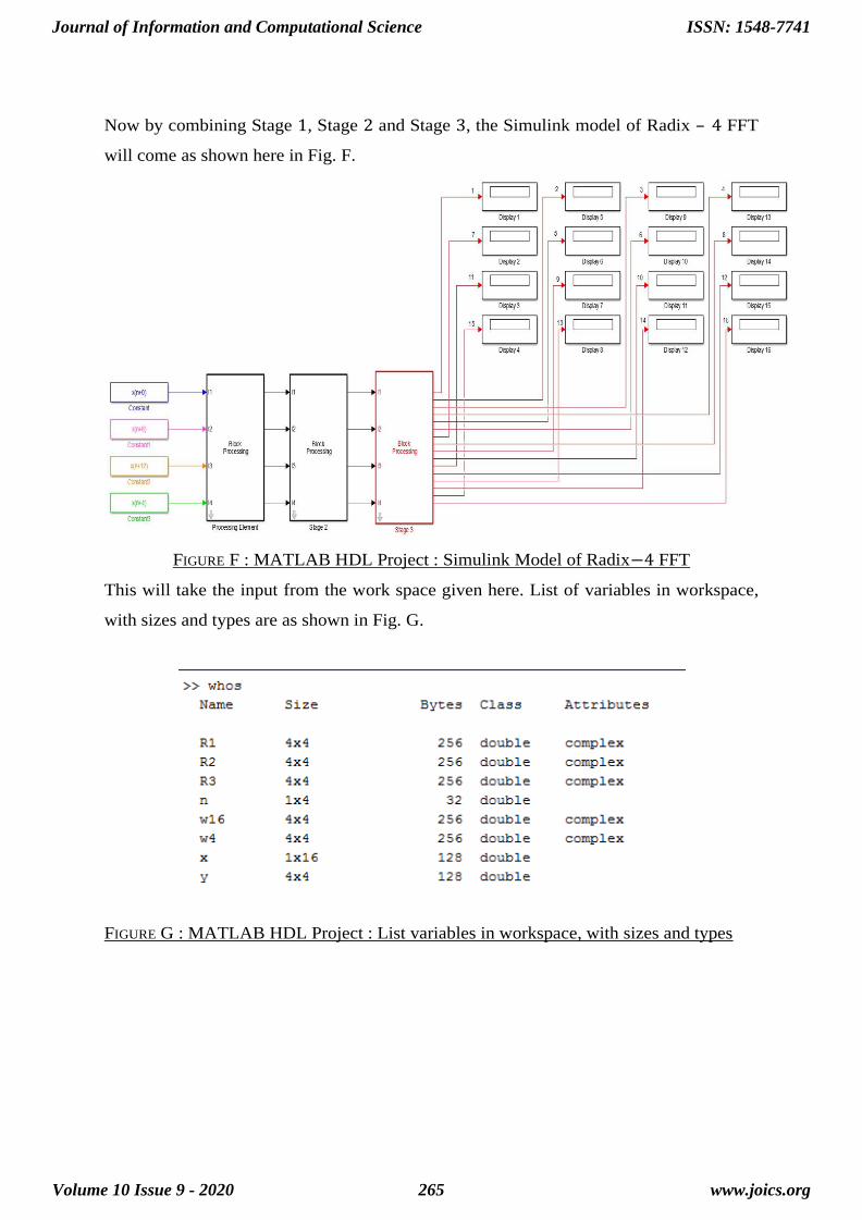
Now by combining Stage 1, Stage 2 and Stage 3, the Simulink model of Radix – 4 FFT
will come as shown here in Fig. F.
FIGURE F : MATLAB HDL Project : Simulink Model of Radix−4 FFT
This will take the input from the work space given here. List of variables in workspace,
with sizes and types are as shown in Fig. G.
FIGURE G : MATLAB HDL Project : List variables in workspace, with sizes and types
Journal of Information and Computational Science
Volume 10 Issue 9 - 2020
ISSN: 1548-7741
www.joics.org265
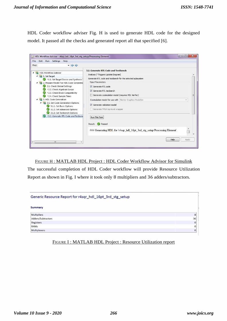
HDL Coder workflow adviser Fig. H is used to generate HDL code for the designed
model. It passed all the checks and generated report all that specified [6].
FIGURE H : MATLAB HDL Project : HDL Coder Workflow Advisor for Simulink
The successful completion of HDL Coder workflow will provide Resource Utilization
Report as shown in Fig. I where it took only 8 multipliers and 36 adders/subtractors.
FIGURE I : MATLAB HDL Project : Resource Utilization report
Journal of Information and Computational Science
Volume 10 Issue 9 - 2020
ISSN: 1548-7741
www.joics.org266

It also provides entire report summary as shown in Fig. J.
FIGURE J : MATLAB HDL Project : HDL Code Generation Summary
HDL generation summary consists of all the information including the Summary,
Resource Utilization Report, Optimization Report, Traceability Report, and Generated
Source Files.
5. Conclusions
In this paper we have shown that the paired transform based FFT algorithm is faster and
can be used at higher sampling rates at an expense of high resource utilization with our
designed FFT processors architectures on Xilinx FPGAs.
The algorithms are modeled into hardware by using Xilinx’s system generator plug-in
software tool running under SIMULINK environment provided under the Mathworks’s
MATLAB software.
The butterfly operation is the main part in the Fast Fourier Transform process upon
which the speed of the complete process of FFT depends. So, as faster the butterfly
operation is, faster will be the FFT process. The block diagram of butterfly operation
consists of adders and subtractors. The adders and subtractors are reduced using the
distributed arithmetic and twiddle factors. And as a result of this the butterfly operation
Journal of Information and Computational Science
Volume 10 Issue 9 - 2020
ISSN: 1548-7741
www.joics.org267
becomes faster and so the FFT.
6. References
[1] James W. Cooley and John W. Tukey, An algorithm for the machine calculation of
complex Fourier Series. Mathematics of Computation, 1965, Volume 19, JSTOR, Pages
297-301. https://www.jstor.org/stable/2003354.
[2] Artyom M. Grigoryan and Sos S. Agaian, Split Manageable Efficient Algorithm for
Fourier and Hadamard transforms Signal Processing. IEEE Transactions, Jan. 2000,
Volume 48, Issue 1, Pages 172 – 183.
[3] Abhinav Ranjan and Shraddha Prasad, Sinusoids and its Orthogonality. Innovations in soft
computing and Information Technology, 2017, Proceedings of ICEMIT ’17, Volume 3, Springer,
Pages 1-6. https://doi.org/10.1007/978-981-13-3185-5_1.
[4] Virtex-4 Pro platform FPGAs. Detailed Description,
http://www.xilinx.com/support/documentation/data_sheets/ ds112.pdf
[5] Narayanam Ranganadh, Parimal A Patel and Artyom M. Grigoryan, Case study of
Grigoryan FFT onto FPGAs and DSPs. IEEE proceedings, December 2013,
International Journal of Future Computer and Communication, Pages 678-681.
[6] S. W. Smith, The Fast Fourier Transform. The Scientist and Engineer’s guide to
Digital Signal Processing, 1999, California Technical Publishing, Chapter 12.
[7] N. Ranganadh, P. Patel, and A.M. Grigoryan, Implementation of the DFT using
Radix-2 and Paired transform algorithms. 17th International Conference on Computer
Applications in Industry and Engineering, CAINE 2004, Orlando, Florida, USA, Nov.
17-19.
[8] N. Ranganadh, P. Patel, and A.M. Grigoryan, Performances of Texas instruments
DSP and Xilinx FPGAs for Cooley-Tukey and Grigoryan FFT algorithms. Wolters
Kluwer and Medknow International Journal of Engineering and Technology, Jul-Dec
2011, Volume 1, Issue 2.
Journal of Information and Computational Science
Volume 10 Issue 9 - 2020
ISSN: 1548-7741
www.joics.org268

[9] Virtex-II Pro platform FPGAs. Detailed Description,
http://www.xilinx.com/support/documentation/data_sheets/ds083.pdf
[10] Virtex-5 platform FPGAs. Detailed Description
http://www.xilinx.com/support/documentation/virtex-5_use
Journal of Information and Computational Science
Volume 10 Issue 9 - 2020
ISSN: 1548-7741
www.joics.org269