a new configuration of dual stator induction generator...
TRANSCRIPT

0885-8969 (c) 2017 IEEE. Personal use is permitted, but republication/redistribution requires IEEE permission. See http://www.ieee.org/publications_standards/publications/rights/index.html for more information.
This article has been accepted for publication in a future issue of this journal, but has not been fully edited. Content may change prior to final publication. Citation information: DOI 10.1109/TEC.2017.2763459, IEEETransactions on Energy Conversion
1
A New Configuration of Dual Stator InductionGenerator Employing Series and Shunt Capacitors
Saptarshi Basak, Student Member, IEEE, Chandan Chakraborty, Fellow, IEEE and Bikash C. Pal, Fellow, IEEE
Abstract—Doubly-fed induction generators are suitable for sys-tems having limited speed range as the overall control can becarried out by fractionally-rated converters. However, brushesand slip-rings used in these generators reduce system reliabilityand demand greater maintenance. Dual stator winding inductiongenerator(DSWIG), being brushless, removes this limitation. Twodistributed windings are embedded in the stator and the rotor issquirrel-cage. One of the windings is interfaced to an uncontrolledrectifier and the other to a fractionally rated PWM converter. Un-controlled rectifier degrades the power quality within the generationsystem. At the same time, reactive power demand in inductiongenerators increases with loading. This work deals with designand control of a standalone dc system based on DSWIG where acombination of passive tuned filter and series capacitor is utilised toaddress the voltage regulation and power quality issue. Simulationresults using MATLAB/Simulink and experimental results (obtainedfrom a laboratory prototype) have been presented, comparedand discussed to demonstrate the effectiveness of the proposedalternative.
Keywords—Brushless Generation Systems, Dual Stator WindingInduction Generator, Micro-Grid, Renewable Energy Extraction.
LIST OF SYMBOLS
ωe Speed of rotating reference frameψdr,ψqr Rotor flux in rotating reference frameψds,ψqs Controlled winding flux in rotating reference frameψdu,ψqu Uncontrolled winding flux in rotating reference
frameICW ,IUW RMS values of controlled and uncontrolled wind-
ing currentsiCW ,iUW Instantaneous values of controlled and uncontrolled
winding currents in time-domainidcs,idcu DC link currents of the converter connected to
controlled winding and uncontrolled winding re-spectively
idr,iqr Rotor currents in rotating reference frameids,iqs Controlled winding currents in rotating reference
frameidu,iqu Uncontrolled winding currents in rotating reference
frameLm Mutual inductance between con-
trolled/uncontrolled winding and RotorLs, Lu, Lr Self inductance of controlled, uncontrolled wind-
ing, and rotor respectivelyLls, Llu, Llr Leakage inductance of controlled, uncontrolled
winding, and rotor respectivelyLus Mutual Inductance between controlled and uncon-
trolled winding
S.Basak and C.Chakraborty are with Department of Electrical Engineering,Indian Institute of Technology Kharagpur.B.C.Pal is with Department of Electrical and Electronic Engineering, ImperialCollege London, SW7 2BT,London.Corresponding author e-mail: [email protected].
Manuscript received April 28, 2017; revised August 23, 2017; acceptedOctober 2, 2017.
mds,mqs Modulation index reference for controlled-windingside converter in d-q reference frame
vdr,vqr Rotor voltages in rotating reference framevds,vqs Controlled winding voltages in rotating reference
framevdu,vqu Uncontrolled winding voltages in rotating refer-
ence framek Power sharing ratio
I. INTRODUCTION
DOUBLY-FED induction machines (DFIMs) have beenfound suitable for motor drives or generation systems
where the speed-range of operation is limited as the controlof the overall system can be performed by a fractionally ratedconverter connected on the rotor side [1]–[3]. Wind-energyconversion system forms one of the best examples of suchapplication [4]. However, brushes and slip-rings are prone tofailure and require regular maintenance. As a result, variousefforts pursued with the development of generation systems ormotor drives where the system is brushless and facilitates controlof the overall system through fractionally-rated converters [5].One such solution is brushless doubly-fed induction machine(BDFIM) [6], [7]. BDFIM comprises of two stator windingswound for different pole configuration and a nested-loop rotor.One of the windings is directly interfaced to the ac-grid andthe other one through a back-to-back converter configuration(similar to DFIMs). However, such machines necessitate use of aspecially-constructed nested-loop rotor, which is a disadvantage.In comparison, self-excited induction generators are rugged andcan be easily manufactured [8]. However, speed-range of suchsystems is narrow. In order to make such systems suitable forvariable-speed generation applications, a full-scale converter hasto be placed on the stator terminals [9]. Use of an additionalstator winding can assist in reducing controlled-converter ratingto a great-extent, especially for dc-mircogrid applications [10].The performance of dual stator winding induction machine (withdifferent pole configuration of stator windings) in motoring modeof operation have been reported in [11]. Torque-sharing functionsfor the two stator windings in order to prevent core saturation hasbeen dealt with in [12]. Control algorithms for open-end windingsplit-phase induction machines have been discussed in [13].This machine has the capability to replace high-power, medium-voltage synchronous machine drive. One such contribution hasbeen described in [14]. Voltage-frequency control using dual sta-tor winding induction generator (DSWIG) for standalone ac loadwas formulated in the pioneering work in [15]. Subsequently,DSWIG has found increased attention for applications like powersupplies for electric vehicle [16], more-electric aircraft [17] aswell as wind electrical systems [18], [19]. DSWIG consists ofa rugged squirrel cage rotor and two windings on the stator,namely power and control winding. Since the two windings arewound for same number of poles, they can influence each otherthrough the electromagnetic coupling. Power-winding deliversactive power to load and control-winding regulates the output

0885-8969 (c) 2017 IEEE. Personal use is permitted, but republication/redistribution requires IEEE permission. See http://www.ieee.org/publications_standards/publications/rights/index.html for more information.
This article has been accepted for publication in a future issue of this journal, but has not been fully edited. Content may change prior to final publication. Citation information: DOI 10.1109/TEC.2017.2763459, IEEETransactions on Energy Conversion
2
voltage with the help of a controlled converter connected acrossit. Since the main purpose of control-winding is to regulateexcitation, the controlled converter rating is much less comparedto the overall rating of generation system. Performances of thesystem for balanced and unbalanced loading have been investi-gated in [20] and [21] respectively. If the application demandssupplying to a standalone dc load, power-winding voltage isrectified using a diode bridge rectifier. Controller developmentfor wide-speed range operation of DSWIG has been reportedin [22] where the boost capability of control winding converterhas been utilised to extend the speed range. Comparative studyof different control strategies for standalone dc system has beenperformed in [23]. Standalone dc systems using DSWIG havingtwo stator windings of different pole configuration has beendiscussed in [24]. However, such systems necessitate use of twoseparate PWM converters corresponding to two stator windings,which is a drawback from the perspective of controlled switchcount. As reported in the literature, the system can work witha combination of uncontrolled and PWM rectifier (with twoseparate dc-links) and without the compensation of lower orderharmonics. However, such a system will have more losses (dueto increased THD of the winding currents) and the output powercapability will degrade. For the same output power, the windingsneed to handle more current. Unlike that of DFIG based systemsreported in [25]–[28], DSWIG comprises of three magneticallycoupled windings. It becomes difficult to compensate for theharmonics by using the controlled winding side converter alone.Therefore, shunt passive filters are deployed at the terminals ofthe winding which is interfaced to the uncontrolled rectifier soas to mitigate the effect of harmonics at the source itself. It isalso well known that induction generators demand reactive powerwith increase in load. This requirement has motivated the authorsto provide compensation in series with the load. Adversely thesystem now requires more number of capacitors, which reducereliability. However, modern film capacitors have low value ofeffective series resistance that makes them less dissipative andso increases life-span. Also, series capacitors possess the abilityto bring about a reactive power change in the right direction.This enhances the stability to a great extent and the systemoffers self-regulation features. Voltage-collapse that is a frequentphenomenon for self-excited induction generators can be com-pletely eliminated by a proper system-design employing series-capacitors. The main contributions presented in this paper are:(i) development of a different configuration of DSWIG which isself-regulatory in nature, (ii) design of passive elements in orderto improve voltage regulation, and (iii) stability improvementaided through incorporation of series capacitance.This paper consists of seven sections. Complete system descrip-tion, mathematical model and design of passive elements arepresented in Section-II. Section-III analyses and compares thestability of the system with and without series capacitor. Section-IV deals with the formulation of controller. MATLAB/Simulinkbased simulation results are presented in Section-V. A dSPACE1103 based laboratory prototype has been fabricated and ex-perimental results obtained using it is reported in Section-VI.Section-VII concludes the work.
II. PROPOSED TOPOLOGY
A. System descriptionThis subsection provides a detailed description of the system
functionalities (corresponding to the topology in Fig. 1). Thestator of DSWIG consists of two windings which are woundfor the same number of poles so that they are magnetically
Fig. 1. Proposed configuration of a standalone dc generating system based onDSWIG (with tuned passive filters and series capacitance)
coupled. The rotor is a squirrel cage type. Since the windings aremagnetically coupled, the variables of one winding can directlyinfluence the other. Thus, the converter connected to controlledwinding (CW) will regulate the excitation within the machine,thereby controlling the induced voltage on the uncontrolledwinding (UW) side. A three-phase diode bridge rectifier rectifiesthis voltage and establishes the dc-bus voltage vdc. Therefore,through excitation control on the controlled winding, vdc canbe regulated. The two converters share a common dc-bus. Thisminimizes the number of electrolytic capacitors and createsa path for simultaneous active power flow through both thewindings. This is made possible by connecting the UW in starand CW in delta, as a voltage gain of
√3 from CW to UW is
introduced. This is necessary as a buck-type operation takes placeas seen from CW to UW side. Supporting derivation is includedin Appendix B. For this particular generator, it is possible to usea parallel combination of uncontrolled and controlled rectifieras active power flow is unidirectional and the reactive poweris supplied by a combination of shunt capacitors Csh, seriescapacitance Cse and controlled winding side converter(CWSC).The presence of diode bridge rectifier (which shares majorportion of the power, especially near to rated speed of operation)will have a detrimental effect on the generating system as thepower quality and the power factor will degrade. Thus, a properconfiguration of passive elements is necessary to deal with thisissue. Tuned passive filters can assist in improving power qualityas well as providing some amount of reactive power supportat fundamental frequency. However, reactive power demand ininduction generators increases with load, which degrade voltageregulation. Therefore, a combination of series and shunt capaci-tors have been chosen as an effective solution. Series capacitancecan provide reactive power compensation in proportion to loadcurrent and thus assists in improving voltage regulation andincreasing power output from the machine.
B. Mathematical Modelling
Simulation model of DSWIG has been developed in MAT-LAB/Simulink. The following equations given by (1)-(6) de-scribes the model in arbitrary reference frame [15].
vdu = Ruidu +dψdudt− ωeψqu (1)
vqu = Ruiqu +dψqudt
+ ωeψdu (2)
0885-8969 (c) 2017 IEEE. Personal use is permitted, but republication/redistribution requires IEEE permission. See http://www.ieee.org/publications_standards/publications/rights/index.html for more information.
This article has been accepted for publication in a future issue of this journal, but has not been fully edited. Content may change prior to final publication. Citation information: DOI 10.1109/TEC.2017.2763459, IEEETransactions on Energy Conversion
3
(a) (b)
(c) (d)
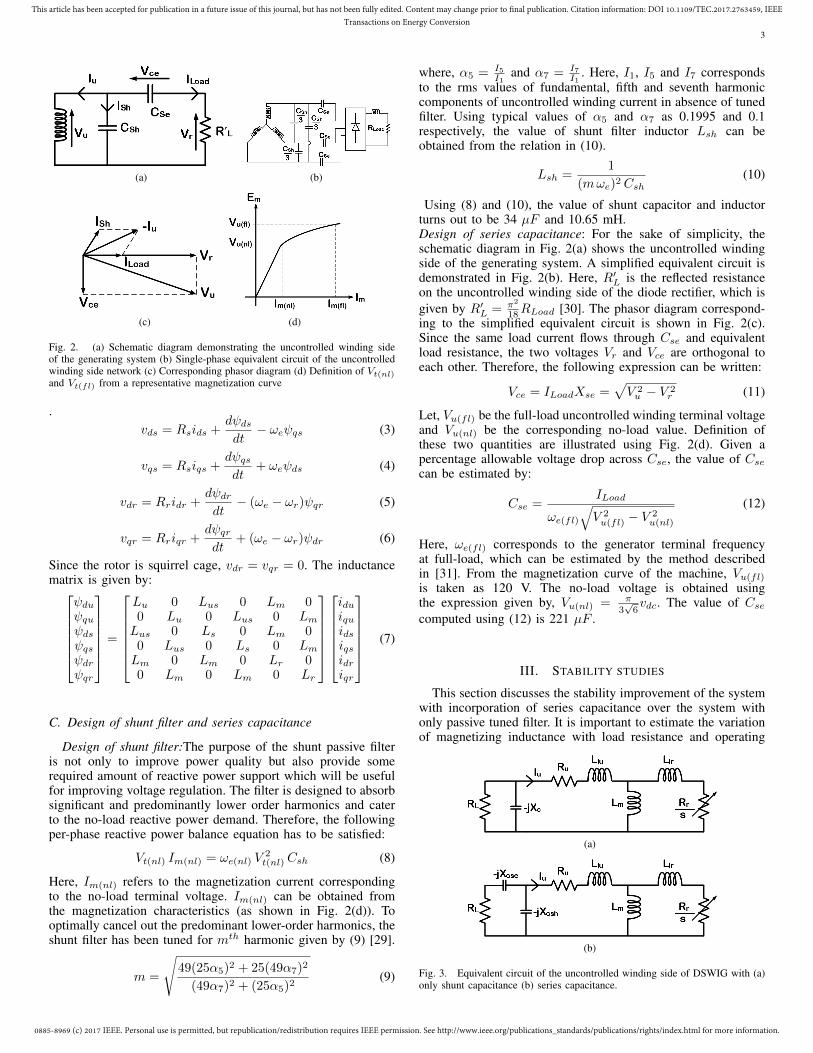
Fig. 2. (a) Schematic diagram demonstrating the uncontrolled winding sideof the generating system (b) Single-phase equivalent circuit of the uncontrolledwinding side network (c) Corresponding phasor diagram (d) Definition of Vt(nl)and Vt(fl) from a representative magnetization curve
.vds = Rsids +
dψdsdt− ωeψqs (3)
vqs = Rsiqs +dψqsdt
+ ωeψds (4)
vdr = Rridr +dψdrdt− (ωe − ωr)ψqr (5)
vqr = Rriqr +dψqrdt
+ (ωe − ωr)ψdr (6)
Since the rotor is squirrel cage, vdr = vqr = 0. The inductancematrix is given by:
ψduψquψdsψqsψdrψqr
=
Lu 0 Lus 0 Lm 00 Lu 0 Lus 0 LmLus 0 Ls 0 Lm 00 Lus 0 Ls 0 LmLm 0 Lm 0 Lr 00 Lm 0 Lm 0 Lr
iduiquidsiqsidriqr
(7)
C. Design of shunt filter and series capacitance
Design of shunt filter:The purpose of the shunt passive filteris not only to improve power quality but also provide somerequired amount of reactive power support which will be usefulfor improving voltage regulation. The filter is designed to absorbsignificant and predominantly lower order harmonics and caterto the no-load reactive power demand. Therefore, the followingper-phase reactive power balance equation has to be satisfied:
Vt(nl) Im(nl) = ωe(nl) V2t(nl) Csh (8)
Here, Im(nl) refers to the magnetization current correspondingto the no-load terminal voltage. Im(nl) can be obtained fromthe magnetization characteristics (as shown in Fig. 2(d)). Tooptimally cancel out the predominant lower-order harmonics, theshunt filter has been tuned for mth harmonic given by (9) [29].
m =
√49(25α5)2 + 25(49α7)2
(49α7)2 + (25α5)2(9)
where, α5 = I5I1
and α7 = I7I1
. Here, I1, I5 and I7 correspondsto the rms values of fundamental, fifth and seventh harmoniccomponents of uncontrolled winding current in absence of tunedfilter. Using typical values of α5 and α7 as 0.1995 and 0.1respectively, the value of shunt filter inductor Lsh can beobtained from the relation in (10).
Lsh =1
(mωe)2 Csh(10)
Using (8) and (10), the value of shunt capacitor and inductorturns out to be 34 µF and 10.65 mH.Design of series capacitance: For the sake of simplicity, theschematic diagram in Fig. 2(a) shows the uncontrolled windingside of the generating system. A simplified equivalent circuit isdemonstrated in Fig. 2(b). Here, R′L is the reflected resistanceon the uncontrolled winding side of the diode rectifier, which isgiven by R′L = π2
18RLoad [30]. The phasor diagram correspond-ing to the simplified equivalent circuit is shown in Fig. 2(c).Since the same load current flows through Cse and equivalentload resistance, the two voltages Vr and Vce are orthogonal toeach other. Therefore, the following expression can be written:
Vce = ILoadXse =√V 2u − V 2
r (11)
Let, Vu(fl) be the full-load uncontrolled winding terminal voltageand Vu(nl) be the corresponding no-load value. Definition ofthese two quantities are illustrated using Fig. 2(d). Given apercentage allowable voltage drop across Cse, the value of Csecan be estimated by:
Cse =ILoad
ωe(fl)√V 2u(fl) − V
2u(nl)
(12)
Here, ωe(fl) corresponds to the generator terminal frequencyat full-load, which can be estimated by the method describedin [31]. From the magnetization curve of the machine, Vu(fl)is taken as 120 V. The no-load voltage is obtained usingthe expression given by, Vu(nl) = π
3√6vdc. The value of Cse
computed using (12) is 221 µF .
III. STABILITY STUDIES
This section discusses the stability improvement of the systemwith incorporation of series capacitance over the system withonly passive tuned filter. It is important to estimate the variationof magnetizing inductance with load resistance and operating
(a)
(b)
Fig. 3. Equivalent circuit of the uncontrolled winding side of DSWIG with (a)only shunt capacitance (b) series capacitance.

0885-8969 (c) 2017 IEEE. Personal use is permitted, but republication/redistribution requires IEEE permission. See http://www.ieee.org/publications_standards/publications/rights/index.html for more information.
This article has been accepted for publication in a future issue of this journal, but has not been fully edited. Content may change prior to final publication. Citation information: DOI 10.1109/TEC.2017.2763459, IEEETransactions on Energy Conversion
4
(a) (b)
Fig. 4. (a) Equivalent shunt network corresponding to the circuit shownin Fig. 2(b), (b) Uncontrolled winding side network represented as a parallelcombination of a resistance and capacitance.
frequency, which are the two important parameters while assess-ing the stability of induction generator systems. Fig. 3 displaysthe corresponding equivalent circuits. Applying loop equations,the circuit can be solved using ΣIuZu = 0. Since Iu 6= 0, thecircuit can be solved by equating the real and imaginary parts ofΣZu to 0. The two resulting simultaneous non-linear equationsare solved to obtain the values of the Lm and ωe for variousload. For the system with only shunt compensation, ΣZu = 0yields the expressions given by (13) and (14). Applying the samecondition for the equivalent circuit in Fig. 3(b), relationships (15)and (16) are obtained.
1
R′L+
1
ωe
(1 +
RuR′L− ω2
eLluCsh
) Rr(ωe − ωr)R2r + L2
lr(ωe − ωr)2
+( Llr(ωe − ωr)2
R2r + (ωe − ωr)2L2
lr
+1
Lm
)(LluR′L
+ CshRu
)= 0
(13)
ω2eCsh −
(1 +
RuR′L− ω2
eCshLlu
)( Llr(ωe − ωr)2
R2r + (ωe − ωr)2L2
lr
+1
Lm
)+ ωe
(LluR′L
+ CshRu
)( Rr(ωe − ωr)R2r + L2
lr(ωe − ωr)2)
= 0
(14)
Ru −C2resR
′L
Csh
1Cse− 1
Cres
1 + (ωeR′LCres)2
+(ωe − ωr)ωeL2
mRr(Rr)2 + (ωe − ωr)2L2
r
= 0
(15)
ωeLlu −Cres
ωeCshCse
[1 + (ωeR′L)2CseCres
1 + (ωeR′LCres)2
]+ωeLm[R2
r + (ωe − ωr)2LlrLr](Rr)2 + (ωe − ωr)2L2
r
= 0
(16)
Here, Cres is the effective capacitance given by Cres =CseCshCse+Csh
.At fundamental frequency, the passive tuned filter behaves as acapacitive circuit. Therefore, it is represented as a ‘frequency-dependent’ capacitive element C1, as shown in Fig. 4(a). Sim-ilarly, the series combination of Cse and R′L are transformedinto a shunt equivalent circuit given by a load dependent capac-itive element C2 and a ‘frequency-dependent’ resistance Req .The parallel combination of C1 and C2 is represented as Ceq(referring to Fig. 4(b)). The mathematical expressions of C1, C2
and Req are given by:
C1 =Csh
1− ω2eLshCsh
, C2 =Cse
1 + (ωeCseR′L)2,
Req =1 + (ωeCseR
′L)2
ω2eC
2seR′L
(17)
Using (10), the capacitance C1 can be expressed as C1 = Csh1− 1
m2.
So, C1 is independent of frequency. For light load conditions,
(R′LωeCse)2 1. Using this approximation, following expres-
sions are obtained:
C2 ≈1
(R′Lωe)2Cse
, Req ≈ R′L (18)
Therefore, at light load conditions, C2 ∝ 1ω2e
and R′eq becomesindependent of frequency, whereas at higher loads R′eq ∝ 1
ω2e
andC2 is independent of frequency. For the configuration with onlyshunt filter, Ceq = C1 and Req = R′L, which are independent offrequency. The uncontrolled winding terminal voltage dynamics(obtained by applying KCL at node ‘A’) can be described by(referring to Fig. 4(b)):
Ceqdvudt
= −(iu + iL) (19)
The machine model, given by (1)-(6), can be re-framed in termsof machine flux linkages as given by:
˙ψdu = −(a11ψdu + a12ψds + a13ψdr)Ru + ωeψqu + vdu
(20.1)˙ψqu = −(a11ψqu + a12ψqs + a13ψqr)Ru − ωeψdu + vqu
(20.2)˙ψds = −(a21ψdu + a22ψds + a23ψdr)Rs + ωeψqs + vds
(20.3)˙ψqs = −(a21ψqu + a22ψqs + a23ψqr)Rs − ωeψds + vqs
(20.4)˙ψdr = −(a31ψdu + a32ψds + a33ψdr)Rr + (ωe − ωr)ψqr
(20.5)˙ψqr = −(a31ψdu + a32ψds + a33ψdr)Rr − (ωe − ωr)ψdr
(20.6)
The constants ai,j and ∆L in (20) are given by:
a11 =LsLr − L2
m
∆L, a12 = a21 =
L2m − LusLr
∆L, (21)
a13 = a31 =Lm(Lus − Ls)
∆L, a22 =
LuLr − L2m
∆L,
a23 = a32 =−Lm(Lu − Lus)
∆L, a33 =
LuLs − L2us
∆L
∆L = Lu(LsLr − L2m)− Lus(LusLr − L2
m) + L2m(Lus − Ls)
Similarly with machine current expressed in terms of fluxlinkages, the behaviour of the terminal voltage across the un-controlled winding in synchronously rotating reference frame isrepresented as:
dvdudt
= −vduτeq− a11ψdu + a12ψds + a13ψdr
Ceq+ ωevqu
dvqudt
= −vquτeq− a11ψqu + a12ψqs + a13ψqr
Ceq− ωevdu
(22)
where τeq = ReqCeq . The machine model (given by (20))and UW terminal voltage dynamics (given by (22)) are clubbedtogether to form the state space model in terms of x =Ax + Bu. Here, the states and inputs are defined as x =[ψdu ψqu ψds ψqs ψdr ψqr vdu vqu] and u = [vds vqs].Corresponding to the each value of load resistance, the corre-sponding value of Lm and stator frequency is recorded (usingthe equivalent circuits shown in Fig. 3) and fed in to the stabilityanalysis program. Eight eigenvalues will result from A-matrix,

0885-8969 (c) 2017 IEEE. Personal use is permitted, but republication/redistribution requires IEEE permission. See http://www.ieee.org/publications_standards/publications/rights/index.html for more information.
This article has been accepted for publication in a future issue of this journal, but has not been fully edited. Content may change prior to final publication. Citation information: DOI 10.1109/TEC.2017.2763459, IEEETransactions on Energy Conversion
5
(a)
(b)
Fig. 5. Movement of pole locations with respect to variation in load resistance(RL = 20Ω to RL = 200Ω) for the configurations with (a) shunt-filter onlyand (b) a combination of series capacitance of 221 µF and shunt passive filter.The values of Lsh and Csh are provided in Appendix A
out of which two of them are found to be dominant. Fig. 5(a)shows the variation of these dominant pole locations with respectto load resistance for the configuration with shunt-filter only.It is interesting to note that the poles begin to move towardsthe right-half of s-plane with the reduction in load resistance.The values of Lm obtained using the equation ΣIuZu = 0exceeds the unsaturated value of Lm (i.e. Lm > Lm(unsat)),which is not a feasible solution. However, it is important to notethe movement of poles with load resistance corresponding tothe two different configurations. The behaviour of the systemchanges when series capacitors are introduced. The dominantpoles move more into the left-half of s-plane with reduction inload resistance, as demonstrated in Fig. 5(b). Therefore, it canbe inferred that deployment of series capacitance enhances thedynamic stability of the system.
IV. DESCRIPTION OF CONTROL ALGORITHM
Here, controlled-winding flux oriented control (CWFOC) hasbeen adopted in order to regulate dc-link voltage to its desiredvalue. In steady-state, the active and reactive power handled bythe controlled winding is expressed as (with respect to the arrowdirections in Fig. 1):
PCW = −3
2(vqsiqs + vdsids) = −Rs(i2ds + i2qs)−
3
2ωeψdsiqs
QCW =3
2(vqsids − vdsiqs) =
3
2ωeψdsids
(23)From (23), it is evident that active power control throughcontrolled-winding is possible through iqs (if Rs is neglected)and that of reactive power through ids. In the proposed topology,reactive power contribution on the uncontrolled-winding sidecomes from two sources, (i) Csh, which generates a fixed amount(ii) Cse, which generates reactive power in proportion to load
current. The reactive power deficit or excess has to be adjusted byQCW . Thus, ids reference is generated from the vdc PI controllersuch that the total reactive power demand (to keep vdc regulated)within the generation system is met. The q-axis current (i.e. iqs)consists of two components (as shown in Fig. 6): (i) iqsL, whichis proportional to the load and (ii) iqsE which is proportional tothe error between actual and reference value of dc-bus voltage.Power sharing ratio, k, takes care how much active power CWSCwill carry. Detailed mathematical derivation of iqsL generationtechnique is available in [29]. The vector rotater is generatedusing the reference voltages (vsα,vsβ) and controlled-windingside currents isα,isβ using the following relationships, where~vs = vsα + jvsβ and ~is = isα + jisβ :
~ψs =
∫(~vs −Rs~is) (24.1)
ρe = arg( ~ψs) (24.2)
V. SIMULATION RESULTS
Simulation studies are conducted in MATLAB/Simulink inorder to explore the merits of the proposed topology. Dynamicperformance of the controller along with harmonic reduction inphase currents are demonstrated through the simulation studiesat a constant speed of 1500 r/min. The suitability of the systemfor variable speed operation has also been investigated. Table-I provides machine parameters used for simulation. All theparameters are referred to the controlled winding side.
A. Dynamic performance at constant speedFirst, the system performance under step change in load is
studied. Before t = 3 s, the system is running at no-load. Astep-change in load of 0.5 kW occurs at t = 3 s as shownin Fig. 7(d). In order to restore the voltage to 220 V after aninitial dip, ids increases from -1.1 to -0.1 A. Since iqs referenceis generated in proportion to load current, it changes to -2 Awith negative sign indicating generating mode of operation. Anadditional load of 500 W is switched on at t = 4 s, which resultsin an increase of ids from -0.1 A to 0.6 A. It is interesting to notethe effect of power-sharing ratio k on ∆ids (i.e. the change inthe value of ids) during the step change in load. When the powersharing ratio is changed to 0.2, the steady-state value of ∆idsreduces to 0.35 A (as shown in Fig. 7(c)). With the decay inthe value of k, more power is pumped through the uncontrolled-winding causing more current to flow through Cse making thesystem more self-regulatory. Thus, control effort reduces withthe reduction in the value of k. Since iqs ∝ k, the value of iqsbecomes almost half for a particular value of load current whenk reduces from 0.4 to 0.2, as noticeable from Fig. 7(b) and 7(c).The dc bus voltage and load current dynamics are of similarnature for k = 0.2 and hence, are not illustrated again.
B. Steady state waveformsFig. 8 shows the steady phase current waveforms for a load
of 1 kW corresponding to a power sharing ratio (k) of 0.4. Thepassive tuned filters have been instrumental in improving thepower quality to a great extent, as shown in Fig. 8(a) and 8(b).Fig. 8(c) reveals that the fifth and seventh harmonic componentof current can be brought to less than 2% of the fundamentalcomponent of current. Similarly, the predominant lower orderharmonics in uncontrolled winding current can be reduced toless than 3% of the fundamental current. The RMS value of

0885-8969 (c) 2017 IEEE. Personal use is permitted, but republication/redistribution requires IEEE permission. See http://www.ieee.org/publications_standards/publications/rights/index.html for more information.
This article has been accepted for publication in a future issue of this journal, but has not been fully edited. Content may change prior to final publication. Citation information: DOI 10.1109/TEC.2017.2763459, IEEETransactions on Energy Conversion
6
Fig. 6. Block diagram showing dc-bus voltage controller (with a provision to regulate power shared among each stator winding)
(a) (b)
(c) (d)
Fig. 7. (a) DC Bus voltage dynamics due to a step change in load for k = 0.4(b) Response of the controlled winding currents when there is a step change inload for k = 0.4 (c) Response of ids and iqs during step change in load fork = 0.2 (d) Discrete changes in load current
controlled winding current waveform is 2.01 A and that ofuncontrolled winding current is 3.68 A. The THD of the iUW is3.02% while that of iCW is 4.25%.
C. Performance for change in speedFig. 9 demonstrates the performance of the system when there
is gradual decrease in prime mover speed. If wind electricalsystem is considered to be the target application, maximumavailable power from wind will reduce in cubic proportion toprime mover speed (i.e. Pout ∝ ω3
m). Thus, the maximumavailable power at 0.6 p.u. speed is 0.216 p.u. with 1 p.u. speed
(a) (b)
(c) (d)
Fig. 8. Line current waveform for (a) uncontrolled and (b) controlled windingcurrent at a load of 1 kW for k = 0.4. Line current spectra for (c) uncontrolledand (d) controlled winding current for same load and power sharing factor.
(a) (b)
(c) (d)
Fig. 9. (a) DC bus voltage dynamics during gradual change in speed (b)Response of controlled winding currents (in rotating reference frame) (c) Decayin speed (d) Steady-state waveform of controlled winding line current
corresponding to a speed of 1500 rpm. Fig. 9(c) shows thevariation of prime mover speed from its rated value to 0.6 p.u.As shown in Fig. 9(a), dc bus voltage is held fairly constant bymeans of ids control, irrespective of this speed change. FromFig. 9(b), it can be seen that ids increases from -0.6 A to 2 A inorder to regulate dc bus to 220 V. Since load on the system isconstant, iqs remains fairly constant at -3.5 A. Fig. 9(d) illustratesthe steady-state phase current waveform at a prime mover speedof 900 r/min. The rms value of line current is 2.72 A and itsTHD is 2.28%.
VI. EXPERIMENTAL RESULTS
A. Dynamic performance during loadingPerformance of the system when subjected to a sudden rise
in load has been experimentally validated and reported here. Adc machine coupled to DSWIG serves the purpose of a primemover which drives the generation system at a speed of 1500r/min. Experimental results are presented for two values of ki.e. k = 0.4 and k = 0.2. Initially, a load of 0.5 kW is presentacross the dc-bus and another 0.5 kW load is applied at t =1.5 s. As result of this sharp change in load, vdc undergoesan initial dip of 6 V and is restored to its original value of220 V within 0.2 s (referring to Fig. 10(a)). The controlled-winding d-axis current increases from -0.5 A to 0, as shownin Fig. 10(c). The reduction in ∆ids with reduction in k hasbeen experimentally verified. When k becomes 0.4, the steady-state value of ids changes from -0.5 to 0.5 A (as depicted inFig. 10(b)). This is due to increased current flow through seriescapacitors which provides better voltage regulation capability.Corresponding simulation results show that the steady-state value
0885-8969 (c) 2017 IEEE. Personal use is permitted, but republication/redistribution requires IEEE permission. See http://www.ieee.org/publications_standards/publications/rights/index.html for more information.
This article has been accepted for publication in a future issue of this journal, but has not been fully edited. Content may change prior to final publication. Citation information: DOI 10.1109/TEC.2017.2763459, IEEETransactions on Energy Conversion
7
(a) (b) (c) (d)
Fig. 10. (a) DC Bus voltage dynamics due to a step change in load for k = 0.2. Response of controlled-winding currents for (b) k = 0.2 and (c) k = 0.4. (d)Discrete change in load current from 2.27 A to 4.54 A
(a) (b) (c)
Fig. 11. Line current waveforms of controlled (CH2, Scale:4 A/div.) and uncontrolled (CH4, Scale: 4 A/div.) winding current at an output power of 1 kW for (a)k=0.4 and (b) k=0.2. (c) Phase voltage waveform (Scale:200 V/div.) of uncontrolled and controlled winding for k=0.2
of ids is 0.6 A for k = 0.4 while it is 0.35 A for k = 0.2. Thisindicates the closeness of simulation and experimental results.Also, iqs changes in proportion to k, as evident from Fig. 10(b)and 10(c).
(a) (b)
Fig. 12. Spectra of the line-current of (a) controlled-winding and (b)uncontrolled-winding for Pout = 1 kW and k = 0.4
(a) (b)
Fig. 13. (a) Line current waveforms of controlled-winding (CH2, Scale:5A/div)and uncontrolled-winding(CH4, Scale:5A/div) at rated load (b) Phase voltagewaveforms (Scale:200 V/div.) at same condition
(a)
(b)
Fig. 14. Variation of total rms current with power sharing ratio for a load of(a) 1 kW and (b) 1.3 kW
B. Steady-state waveforms and load characteristics
This subsection reports the steady-state performance of thegeneration system for a fixed speed of 1500 rpm. Fig. 11 showsthe line current and phase voltage waveforms. The variation of

0885-8969 (c) 2017 IEEE. Personal use is permitted, but republication/redistribution requires IEEE permission. See http://www.ieee.org/publications_standards/publications/rights/index.html for more information.
This article has been accepted for publication in a future issue of this journal, but has not been fully edited. Content may change prior to final publication. Citation information: DOI 10.1109/TEC.2017.2763459, IEEETransactions on Energy Conversion
8
Fig. 15. Variation of maximum output power with the magnitude of per-phaseseries capacitance corresponding to rated speed of operation
rms values of line current with the variation in k is studied.For a load of 1 kW and k = 0.4, IUW is 2.96 A and ICW is2.26 A. When the value of k is reduced to 0.2, IUW increasesto 3.74 A and ICW reduces to 0.8 A, which indicates thatcurrent share of each winding can be governed by power sharingfactor. Deployment of tuned passive filter assists in improvingcurrent quality to a large extent. The fifth and seventh harmoniccomponents in uncontrolled-winding current is reduced to <1%and 3.16% respectively while that of controlled-winding islowered to 2% and 3.16% respectively, as shown in Fig. 12. TheTHD of IUW at k = 0.4 is 4.89% while that for ICW at samevalue of k is 5.8 %. Since the rms value of phase voltage doesnot undergo a significant change with change in value of k, onlya waveform corresponding to k = 0.4 has been demonstrated.The line-current and phase-voltage waveforms at rated load havebeen displayed in Fig. 13. The rms value of uncontrolled-windingline current is 4.51 A (with a THD of 4.77%) while that ofcontrolled-winding is 3.5 A (with a THD of 4.92%). The totalreactive power demand of the generator system corresponding tothe rated load of operation is found to be Qtot = 1274.38 VAR.The shunt capacitors and series capacitors are able to providereactive power support of 389 VAR and 591 VAR respectively.The apparent power handled by the converter in the presenceand absence of series capacitors is 691.66 VA and 1083.6 VArespectively. Therefore, the inclusion of series capacitors allow a36% reduction in apparent power rating of controlled converter.Performance comparison against configuration with shunt filteronly: Fig. 14 shows the variation of total rms current with powersharing ratio for two different loads of 1 kW and 1.3 kW, wheretotal rms current is defined as Itot =
√I2UW + I2CW . From
the plots, it can be seen that Itot is less for the configurationwith series capacitor than the configuration with shunt capac-itor, corresponding to a particular value of k and load. Seriescapacitor assists in raising the magnitude of terminal voltage ofuncontrolled winding (as evident from the phasor diagram inFig. 2(c)) and reduces the angle between the terminal voltageand current of uncontrolled winding. Thus, Itot reduces andthe overall power-factor within the generation system improves.The power available from the machine can be enhanced. Theminimum value of Itot corresponding to 1 kW is 3.23 A withseries capacitance and 3.48 A without series capacitance. For aload of 1.3 kW, the minimum value of Itot is 4.2 A and 4.4 Awith and without series capacitors respectively.Fig. 15 demonstrates the variation of maximum output powerwith the magnitude of series capacitance. The voltage drop acrossthe series capacitance at rated value of uncontrolled windingcurrent is given by Vcse = Iur
ωeCse, where Iur denotes the rms
value of uncontrolled-winding current at rated load. With thedecrease in the value of Cse, the voltage drop across it andthe corresponding terminal voltage across uncontrolled-winding
increases. Therefore, with the reduction in the value of Cse,more active power can be extracted from the generation system.However, further decrease in Cse causes even higher terminalvoltage across uncontrolled winding which pushes the machineinto saturation region. This creates higher reactive power demandand the active power output capability of the machine degrades.This is experimentally validated in the plot shown in Fig. 15.Compared to the configuration with shunt passive filter only,the maximum output power which can be obtained is 1.45 kW.Proper choice of Cse will result in enhancing the maximumpower output to 1.66 kW. A 14.55% increase in Pmax is notedwhich makes the scheme beneficial compared to that reported in[29].
C. Operation at different prime mover speedsThe performance of generating system for different prime-
mover speeds has been experimentally investigated (consideringwind power generation as the target application) and reported inthis sub-section. Since Pout ∝ ω3
r for wind electrical systems,major share of active power takes place through the controlled-winding in the low-speed region where the total output powerdoes not exceed the rating of CWSC. Fig. 16(a) shows thecontrolled-winding voltages and currents at a speed of 1000 rpm(0.66 p.u.) corresponding to an output power of 0.2963 p.u..The value of ICW is 3.44 A and the corresponding THD is2.88%. Similar waveforms have been demonstrated for a speedof 900 rpm (0.6 p.u.) and 0.216 p.u. output power in Fig.16(b) where the rms value of ICW is 2.95 A with a THDof 2.57%. The steady-state values of ids and iqs are 1.7 Aand -3.7 A respectively, which has close resemblance with thevalues attained through simulation results shown in Fig. 9(b).The minimum speed required to regulate the output voltage to220 V is 800 rpm (0.533 p.u.) with an output power of 0.152p.u. Corresponding result is shown Fig. 16(c). Here, ICW settlesat 2.76 A.
VII. CONCLUSION
A different configuration of DSWIG for a standalone dcgeneration system has been reported. The major aim is toimprove output voltage regulation and power quality within thegenerating system through a combination of passive tuned filtersand series capacitors. While passive tuned filters can absorb thepredominant lower order harmonics and supply approximatelyfixed amount of reactive power, series capacitors will providereactive power support in proportion to load current. Thus thesystem attains self-regulating characteristics by selecting propervalues of series capacitance. A study shows that stability of thesystem improves with the increase in load. Compared to shunt-only compensation based system, the proposed configurationoffers better power factor and extracts more active power. Asimple method to select the magnitude of Cse is also discussed.Simulation studies have been conducted on MATLAB/Simulinkand corresponding results have been presented. Experimentalresults obtained using a dSPACE 1103 based laboratory pro-totype has been provided. Both simulation and experimentalresults confirm the effectiveness of the proposed configurationin improving voltage regulation in a DSWIG based standalonedc system. Experimental investigations reveal proper choice ofseries capacitor can enhance the output power by about 15%.
ACKNOWLEDGEMENT
The authors acknowledge the support from Department ofScience and Technology(DST), Government of India through the

0885-8969 (c) 2017 IEEE. Personal use is permitted, but republication/redistribution requires IEEE permission. See http://www.ieee.org/publications_standards/publications/rights/index.html for more information.
This article has been accepted for publication in a future issue of this journal, but has not been fully edited. Content may change prior to final publication. Citation information: DOI 10.1109/TEC.2017.2763459, IEEETransactions on Energy Conversion
9
(a) (b) (c)
Fig. 16. Controlled-winding voltage (CH1, Scale: 200 V/div.) and current (CH2, Scale:4 A/div.) for prime-mover speeds of (a)1000 rpm, (b)900 rpm, (c)800 rpm
project “Reliable and Efficient System for Community EnergySolution (RESCUES)” with joint collaboration of DST, India andEngineering and Physical Research Council (EPSRC), UK.
APPENDIX AMACHINE PARAMETERS
Machine parameters and magnetization curve are presented inTable-I and Fig. 17.
Fig. 17. Magnetization curve of the machine at 50 Hz (as seen from thecontrolled winding side)
TABLE I. MACHINE RATINGS AND PARAMETERS
Symbol Parameter Nominal ValueIs(rated) Rated current of controlled Winding 2.3 A
Iu(rated) Rated current of uncontrolled winding 4.5 A
V(rated) Rated voltage of each winding 100 V
P Number of poles 4Rs Resistance of controlled winding 6.33 Ω
Ru Resistance of uncontrolled winding 5.64 Ω
Rr Resistance of rotor bars 2.96 Ω
Lm Magnetizing inductance (unsaturated value) 300.48 mHLus Mutual inductance between controlled and uncontrolled winding (un-
saturated value)296.24 mH
Lls Controlled winding leakage inductance 9.23 mHLlu Uncontrolled winding leakage inductance 6.56 mHLlr Rotor leakage inductance 7.89 mHLf Shunt filter inductance at uncontrolled winding side 12 mH, 1 ACf Shunt filter capacitance at uncontrolled winding side 48 µF, 100 VCdc DC-link capacitor 2200 µF, 315 V
APPENDIX BWINDING CONFIGURATIONS OF STATOR WINDINGS
The generic configuration of a DSWIG-DC system is demon-strated in Fig. 18. This section illustrates the limitations whicharises if both the stator windings are connected in star with unityturns ratio between them. Let, Vcdc be the dc bus voltage onthe controlled winding side converter. The maximum rms valuewhich CWSC can impress on CW is given by VCW = Vcdc√
2. For
unity turns ratio, VCW = VUW . In such a situation, the maximum
Fig. 18. Generic configuration of dual stator winding induction generator withtwo isolated dc buses.
output voltage of the diode bridge rectifier on the UW side (atno-load) is given by:
Vudc =3√
2
πVUW =
3
πVcdc (B1)
Under loaded condition, the output voltage Vucdc will reduceeven further. From (B1), it is evident that it is a buck-typeoperation from CW side to UW side. Therefore, the output of thediode-bridge rectifier and the PWM-controlled converter cannotbe connected in parallel. Connecting the CW in delta and UWin star, a voltage gain of
√3 is introduced and the two dc buses
can be merged into a single one.
REFERENCES
[1] Y. Yao, A. Cosic, and C. Sadarangani, “Power Factor Improvement andDynamic Performance of an Induction Machine With a Novel Concept ofa Converter-Fed Rotor,” IEEE Trans. Energy Convers., vol. 31, no. 2, pp.769–775, June 2016.
[2] N. K. S. Naidu and B. Singh, “Doubly Fed Induction Generator for WindEnergy Conversion Systems With Integrated Active Filter Capabilities,”IEEE Trans. Ind. Informat., vol. 11, no. 4, pp. 923–933, Aug 2015.
[3] Y. Song and H. Nian, “Enhanced Grid-Connected Operation of DFIGUsing Improved Repetitive Control Under Generalized Harmonic PowerGrid,” IEEE Trans. Energy Convers., vol. 30, no. 3, pp. 1019–1029, Sept2015.
[4] S. Mondal and D. Kastha, “Improved Direct Torque and Reactive PowerControl of a Matrix-Converter-Fed Grid-Connected Doubly Fed InductionGenerator,” IEEE Trans. Ind. Electron., vol. 62, no. 12, pp. 7590–7598,Dec 2015.
[5] F. Blaabjerg and K. Ma, “Future on Power Electronics for Wind TurbineSystems,” IEEE J. Emerg. Sel. Topics Power Electron., vol. 1, no. 3, pp.139–152, Sept 2013.

0885-8969 (c) 2017 IEEE. Personal use is permitted, but republication/redistribution requires IEEE permission. See http://www.ieee.org/publications_standards/publications/rights/index.html for more information.
This article has been accepted for publication in a future issue of this journal, but has not been fully edited. Content may change prior to final publication. Citation information: DOI 10.1109/TEC.2017.2763459, IEEETransactions on Energy Conversion
10
[6] F. Barati, R. McMahon, S. Shao, E. Abdi, and H. Oraee, “GeneralizedVector Control for Brushless Doubly Fed Machines With Nested-LoopRotor,” IEEE Trans. Ind. Electron., vol. 60, no. 6, pp. 2477–2485, June2013.
[7] J. Chen, W. Zhang, B. Chen, and Y. Ma, “Improved Vector Controlof Brushless Doubly Fed Induction Generator under Unbalanced GridConditions for Offshore Wind Power Generation,” IEEE Trans. EnergyConvers., vol. 31, no. 1, pp. 293–302, March 2016.
[8] B. Singh, S. S. Murthy, and R. S. R. Chilipi, “STATCOM-Based Controllerfor a Three-Phase SEIG Feeding Single-Phase Loads,” IEEE Trans. EnergyConvers., vol. 29, no. 2, pp. 320–331, June 2014.
[9] M. Bai and D. Vukadinovi, “Online Efficiency Optimization of a VectorControlled Self-Excited Induction Generator,” IEEE Trans. Energy Con-vers., vol. 31, no. 1, pp. 373–380, March 2016.
[10] S. Basak and C. Chakraborty, “Dual Stator Winding Induction Machine:Problems, Progress, and Future Scope,” IEEE Trans. Ind. Electron.,vol. 62, no. 7, pp. 4641–4652, July 2015.
[11] A. R. Munoz and T. A. Lipo, “Dual stator winding induction machinedrive,” IEEE Trans. Appl. Ind., vol. 36, no. 5, pp. 1369–1379, Sep 2000.
[12] J. M. Guerrero and O. Ojo, “Total Airgap Flux Minimization in Dual StatorWinding Induction Machines,” IEEE Trans. Power Electron., vol. 24, no. 3,pp. 787–795, March 2009.
[13] N. A. Azeez, K. Gopakumar, J. Mathew, and C. Cecati, “A HarmonicSuppression Scheme for Open-End Winding Split-Phase IM Drive UsingCapacitive Filters for the Full Speed Range,” IEEE Trans. Ind. Electron.,vol. 61, no. 10, pp. 5213–5221, Oct 2014.
[14] K. Hatua and V. T. Ranganathan, “A Novel VSI- and CSI-Fed ActiveReactive Induction Motor Drive with Sinusoidal Voltages and Currents,”IEEE Trans. Power Electron., vol. 26, no. 12, pp. 3936–3947, Dec 2011.
[15] O. Ojo and I. Davidson, “PWM-VSI Inverter-Assisted Stand-Alone DualStator Winding Induction Generator,” IEEE Trans. Appl. Ind., vol. 36,no. 6, pp. 1604–1611, Nov 2000.
[16] M. Naidu and J. Walters, “A 4-kW 42-V Induction-Machine-BasedAutomotive Power Generation System With a Diode Bridge Rectifier anda PWM Inverter,” IEEE Trans. Appl. Ind., vol. 39, no. 5, pp. 1287–1293,Sept 2003.
[17] F. Bu, Y. Hu, W. Huang, and S. Zhuang, “Parameter Design and StaticPerformance of Dual Stator-Winding Induction Generator Variable Fre-quency AC Generating System With Inductive and Capacitive Loads,”IEEE Trans. Ind. Electron., vol. 61, no. 8, pp. 3902–3914, Aug 2014.
[18] Y. Li, Y. Hu, W. Huang, L. Liu, and Y. Zhang, “The Capacity Optimizationfor the Static Excitation Controller of the Dual-Stator-Winding InductionGenerator Operating in a Wide Speed Range,” IEEE Trans. Ind. Electron.,vol. 56, no. 2, pp. 530–541, Feb 2009.
[19] F. Bu, W. Huang, Y. Hu, and K. Shi, “An Excitation-Capacitor-OptimizedDual Stator-Winding Induction Generator With the Static ExcitationController for Wind Power Application,” IEEE Trans. Energy Convers.,vol. 26, no. 1, pp. 122–131, March 2011.
[20] F. Bu, Y. Hu, W. Huang, and S. Zhuang, “Parameter Design and StaticPerformance of Dual Stator-Winding Induction Generator Variable Fre-quency AC Generating System With Inductive and Capacitive Loads,”IEEE Trans. Ind. Electron., vol. 61, no. 8, pp. 3902–3914, Aug 2014.
[21] M. Moradian and J. Soltani, “An Isolated Three-Phase Induction Gen-erator System With Dual Stator Winding Sets Under Unbalanced LoadCondition,” IEEE Trans. Energy Convers., vol. 31, no. 2, pp. 531–539,June 2016.
[22] F. Bu, Y. Hu, W. Huang, S. Zhuang, and K. Shi, “Wide-Speed-Range-Operation Dual Stator-Winding Induction Generator DC Generating Sys-tem for Wind Power Applications,” IEEE Trans. Power Electron., vol. 30,no. 2, pp. 561–573, Feb 2015.
[23] H. Xu, F. Bu, W. Huang, Y. Hu, H. Liu, and Y. Zhao, “Analysis,Comparison, and Discussion of Control Strategies for Dual Stator-WindingInduction Generator DC Generating System,” IEEE J. Emerg. Sel. TopicsPower Electron., vol. 4, no. 3, pp. 1007–1014, Sept 2016.
[24] Z. Wu, O. Ojo, and J. Sastry, “High-Performance Control of a Dual StatorWinding DC Power Induction Generator,” IEEE Trans. Appl. Ind., vol. 43,no. 2, pp. 582–592, March 2007.
[25] M. F. Iacchetti, G. D. Marques, and R. Perini, “Torque Ripple Reductionin a DFIG-DC System by Resonant Current Controllers,” IEEE Trans.Power Electron., vol. 30, no. 8, pp. 4244–4254, Aug. 2015.
[26] G. D. Marques and M. F. Iacchetti, “Minimization of Torque Ripple in
the DFIG-DC System via Predictive Delay Compensation,” IEEE Trans.Ind. Electron. (in early access).
[27] G. D. Marques, D. M. Sousa, and M. F. Iacchetti, “Air-Gap Power-BasedSensorless Control in a DFIG Connected to a DC Link,” IEEE Trans.Energy Convers., vol. 30, no. 1, pp. 367–375, Mar. 2015.
[28] H. Misra, A. Gundavarapu, and A. K. Jain, “Control Scheme for DCVoltage Regulation of Stand-Alone DFIG-DC System,” IEEE Trans. Ind.Electron., vol. 64, no. 4, pp. 2700–2708, Apr. 2017.
[29] S. Basak and C. Chakraborty, “A New Optimal Current Control Techniquefor Dual Stator Winding Induction Generator,” IEEE J. Emerg. Sel. TopicsPower Electron., vol. 5, no. 2, pp. 820–832, Jun. 2017.
[30] N. Mohan, T. M. Undeland, and W. P. Robbins, Power Electronics.Converters, Applications and Design, 3rd ed. John Wiley and Sons,Inc, 2003.
[31] C. Chakraborty, S. N. Bhadra, A. K. Chattopadhyay, and S. K. Biswas,“A Novel Two Phase Self Excited Induction Generator-Series ConnectedConverter System as DC Power Supply,” in Conference Record of the 1994IEEE Industry Applications Society Annual Meeting, 1994., Oct 1994, pp.38–43 vol.1.
Saptarshi Basak (S’14) received his B.E. degree inElectrical Engineering from Jadavpur University andM. Tech Degree in Electrical Engineering with special-ization in Machine, Drives and Power Electronics fromIndian Institute of Technology Kharagpur in the year2010 and 2012 respectively. He is pursuing his Ph.Din the Department of Electrical Engineering, Indian In-stitute of Technology Kharagpur. His research interestsinclude Design and Control of Brushless GenerationSystems, and Estimation Techniques and Control of ACDrives.
Chandan Chakraborty (S’92-M’97-SM’01-F’15) re-ceived B.E and M.E degrees in Electrical Engineeringfrom Jadavpur University in 1987 and 1989 respectivelyand Ph.D degrees from Indian Institute of TechnologyKharagpur and Mie University, Japan in 1997 and 2000respectively. Presently, he is a professor in the De-partment of Electrical Engineering, Indian Institute ofTechnology Kharagpur. His research interest includespower converters, motor drives, electric vehicles andrenewable energy.Dr. Chakraborty was awarded the JSPS Fellowship to
work at the University of Tokyo during 2000-2002. He has received the BimalBose award in power electronics in 2006 from the IETE (India). He has regularlycontributed to IES conferences such as IECON, ISIE and ICIT as technicalprogram chair/track chair. He is an ADCOM member of the IEEE IndustrialElectronics Society. He is one of the Associate Editors of IEEE Transactions onIndustrial Electronics and IEEE Industrial Electronics Magazine and an Editorof the IEEE Transactions on Sustainable Energy. He is the Founding Editor-in-Chief of IE Technology News (ITeN), a web-only publication for IEEE IndustrialElectronics Society. He is a Fellow of IEEE and Indian National Academy ofEngineering (INAE).
Bikash C. Pal (M’00-SM’02-F’13) is Professor ofPower Systems at Imperial College London. He isresearch active in power system stability, control andcomputation. Prof. Pal has graduated 17 PhDs andpublished 70 technical papers in IEEE Transactionsand IET journals. He has co-authored two books andtwo award winning IEEE Task Force/Working Groupreports. He is Editor-in-Chief of IEEE Transactionson Sustainable Energy and Fellow of IEEE for hiscontribution to power system stability and control.

本文献由“学霸图书馆-文献云下载”收集自网络,仅供学习交流使用。
学霸图书馆(www.xuebalib.com)是一个“整合众多图书馆数据库资源,
提供一站式文献检索和下载服务”的24 小时在线不限IP
图书馆。
图书馆致力于便利、促进学习与科研,提供最强文献下载服务。
图书馆导航:
图书馆首页 文献云下载 图书馆入口 外文数据库大全 疑难文献辅助工具