a new algorithm for u-shaped two-sided assembly line · pdf filea new algorithm for u-shaped...
TRANSCRIPT

A NEW ALGORITHM FOR U-SHAPED TWO-SIDED ASSEMBLY LINEBALANCING
Mustafa Fatih Yegul1, Kursad Agpak2, Mustafa Yavuz1,3
1Department of Mechanical & Mechatronics Engineering, University of Waterloo, ON, Canada
2Department of Industrial Engineering, Gaziantep University, Gaziantep, Turkey3
Department of Industrial Engineering, Cankaya University, Ankara, Turkey
E-mail: [email protected]
Received November 2009, Accepted May 2010
No. 09-CSME-66, E.I.C. Accession 3152
ABSTRACT
This study introduces a new hybrid design for a specific case of assembly lines, and proposes amulti-pass random assignment algorithm to find the minimum number of stations required. Thealgorithm also finds the sequence and the schedule of the tasks assigned. The new design is acombination of two-sided lines and U-shaped lines, which benefits from the advantages of bothdesigns at the same time. One side of the line is arranged in U-shape allowing stations with cross-overs, and the other side of the line is balanced like a traditional straight flow. Depending onproduct direction, either Left or Right side of the line can be designed in U-shape. Small andlarge-sized two-sided assembly line test-bed problems were solved using the algorithm. Optimalresults are achieved for all small-sized problems. Due to the novelty of the design, results of large-sized problems are compared to findings of studies on simple two-sided balancing. Algorithmproduced better results in most of the cases.
Keywords: two-sided assembly line; assembly line balancing; U-shaped assembly line;COMSOAL; multi-pass assignment heuristic.
UN NOUVEL ALGORITHME POUR L’EQUILIBRAGE D’UNE CHAINE DEMONTAGE A DEUX COTES EN FORME DE U
RESUME
Cette conception hybride innovatrice est destinee a un cas specifique de chaıne de montage, etpropose un algorithme d’assignation aleatoire «multipasse» pour trouver le nombre de postesrequis. L’algorithme trouve egalement la sequence et l’ordonnancement de l’assignation destaches. Le nouveau concept est une combinaison d’une chaıne a deux cotes et chaınes, dont undes cotes est en forme de U, lesquels beneficient des avantages des deux conceptions en memetemps. Un cote de la chaıne est dispose en U pour lui permettre d’avoir des postes de liaison,l’autre cote de la chaıne etant equilibre de facon traditionnelle de regularisation du debit.Dependant de la direction, le cote gauche ou droit de la chaıne peut etre en forme de U. Dans lecas de petite et longue chaıne de montage a deux cotes, des problemes ont ete resolus a l’etapedu banc d’essai en utilisant l’algorithme. Des resultats optimaux ont ete obtenus pour tous lesproblemes de petites chaınes de montage. A cause de la nouveaute du concept, les resultats surles grandes chaınes de montage sont compares aux resultats d’etude sur l’equilibrage de chaınesa deux cotes simples. L’algorithme a produit de meilleurs resultats dans presque tous les cas.
Transactions of the Canadian Society for Mechanical Engineering, Vol. 34, No. 2, 2010 225
1. INTRODUCTION
Assembly line balancing problem has been subject to great interest from researchers fordecades, which may come in various forms based on shape of the line (straight/U-shaped/parallel/two-sided), the number of different products to be manufactured on the same line(single, multi or mixed model) or the type of the input data (deterministic/stochastic/fuzzy).
One of the line balancing problems that has drawn attention from researchers lately, is thetwo-sided assembly line balancing problem. This type of balancing problem in real life is mostlyseen in big scale production lines such as production of cars and buses. In two-sided lines,different from the traditional straight lines, both sides of the line are used for assembly. Asrelated studies indicate, two-sided assembly lines have a number of advantages when comparedto traditional straight lines. Furthermore, two-sided assembly lines are suitable for producinghybrid designs by merging with other types of line designs. For instance, Ozcan et al. [1]proposed a new line design, where two-sided and parallel lines are used together. In this way,advantages of both types of line design can be benefitted at the same time.
U-shaped design is another type of assembly line that offers various benefits over traditionalstraight lines. Key element of U-shaped lines is the use of cross-over stations. To our bestknowledge, yet, there is no research that deals with solution of two-sided assembly lines withone side benefiting the advantages of cross-over stations. In this study, a new two-sided linedesign is proposed, which also accommodates cross-over stations through the U-shaped designon one side of the line. Also, a new line balancing heuristic algorithm is introduced forbalancing of the new line design. New design introduces a practical new approach formanufacturers, who may want to exploit the benefits of both two-sided and U-shaped lines atthe same time. It also has the potential to generate a balance with fewer stations than that ofstraight two-sided lines.
Remainder of the paper is organized as follows. Section two of the paper briefly explains U-shaped lines and cross-over stations, and two-sided lines with literature review. Section threedescribes the line balancing problem for the proposed new design. Section four explains theheuristic solution algorithm, while the section five depicts the experimental results compared toprevious findings of other researchers for straight two-sided lines. Finally, paper ends withconclusion and suggestions for future research. A numerical example is given in appendix.
2. LITERATURE REVIEW
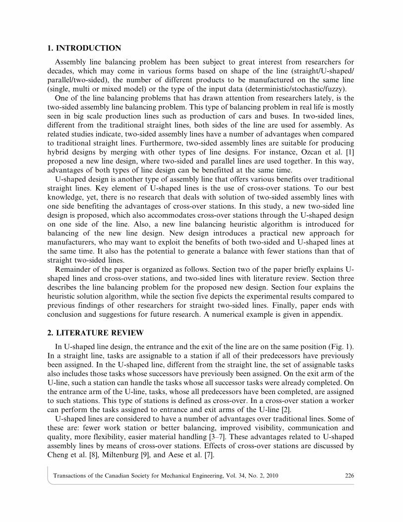
In U-shaped line design, the entrance and the exit of the line are on the same position (Fig. 1).In a straight line, tasks are assignable to a station if all of their predecessors have previouslybeen assigned. In the U-shaped line, different from the straight line, the set of assignable tasksalso includes those tasks whose successors have previously been assigned. On the exit arm of theU-line, such a station can handle the tasks whose all successor tasks were already completed. Onthe entrance arm of the U-line, tasks, whose all predecessors have been completed, are assignedto such stations. This type of stations is defined as cross-over. In a cross-over station a workercan perform the tasks assigned to entrance and exit arms of the U-line [2].
U-shaped lines are considered to have a number of advantages over traditional lines. Some ofthese are: fewer work station or better balancing, improved visibility, communication andquality, more flexibility, easier material handling [3–7]. These advantages related to U-shapedassembly lines by means of cross-over stations. Effects of cross-over stations are discussed byCheng et al. [8], Miltenburg [9], and Aese et al. [7].
Transactions of the Canadian Society for Mechanical Engineering, Vol. 34, No. 2, 2010 226
In U-lines, benefits that can be associated with the cross-over stations are listed by Chenget al. [8] as follows:
i) In U-lines with cross-over stations, more operators examine the product when it is almostcompleted.
ii) The probability of missing quality problems decreases when there are cross-over stations.iii) Operators on a U-line with cross-over stations work alongside more than they do on a
straight line. This facilitates teamwork in quality improvement activities.iv) Crossover stations increase the number of contact points between operators, which
improves communication.
Another benefit addressed by Miltenburg [9] is as follows: ‘‘A U-line with cross-over stationsis better able to reduce the effect of breakdowns than a straight line, when the buffer inventoriesare located at all contact points.’’
Like the traditional line balancing problem, U-line balancing problem is also NP hard nature[10]. In this type of problems the computational time to obtain the optimal solution increasesexponentially as the problem size increases, which make the problem difficult to solve optimally[11]. There are methods proposed by a number of researchers for solving U-lines, which includeScholl and Klein [12], Urban [13], Hwang et al. [14], Aese et al. [15] and Gokcen et al. [16].Furthermore, review papers by Miltenburg [4,5], and Boysen et al. [17,18] can also be examined.
Another classification for assembly lines is with regards to whether or not the workstationsare located on both sides of the line. If operators are stationed only on one side of the line, thenthis is a traditional one-sided line. If line is designed to allow operators to work on both sides ofthe line (left and right), it is called a two-sided line. Two-sided assembly lines are mostly used toproduce large-sized products, such as buses, automobiles etc. In two-sided lines, tasks areperformed at a certain side of the line (L:left or R:right) or either side (E) of the line [19].
A two-sided line may offer a number of benefits over a one-sided line. Bartholdi [20] explainsthese benefits as follows: ‘‘on a two-sided line (Fig. 2) the workers at each pair of oppositestations work in parallel on different tasks but on the same individual item. A two-sided linemay offer a number of benefits over a one-sided line. On a two-sided line some task times mightbe shorter since the worker can avoid setup times in which he repositions himself for tasks likemounting a wheel on the other side of the vehicle. Also a two-sided line can be more space-efficient since the line can be shorter in length than a one-sided line. A shorter line can reduce
Fig. 1. U-shaped assembly line (stations may have cross-overs).
Transactions of the Canadian Society for Mechanical Engineering, Vol. 34, No. 2, 2010 227

material handling costs since it mitigates the need for workers to manoeuvre tools, parts, or theitem. In addition, there might be savings when workers at a pair of stations can share tools orfixtures, such as electrical or air outlets.’’ Furthermore, it is shown that in some cases two-sidedlines may require fewer stations than that of a one-sided line [20].
Limited number of research exists regarding balancing of two-sided assembly lines. As two-sided lines are, too, NP-hard problems [20], most researchers proposed heuristic solution methodssuch as ant colony algorithms [21,22], simulated annealing [19,23] and genetic algorithms [24,25].There are also exact solution algorithms such as branch-and-bound and mathematical modelsintroduced by some authors [19,24,26]. Lapierre and Ruiz [27] developed a software applicationbased on a real case study, which finds near-optimal balances for two-sided lines.
Ozcan et al. [1] introduced a new design where two or more two-sided lines are located inparallel, combining the gains of both two-sided and parallel lines. They developed a tabu-searchalgorithm for balancing the parallel two-side lines. Results show that new design requires eitherthe same number of stations or fewer stations when compared to straight two-sided lines.
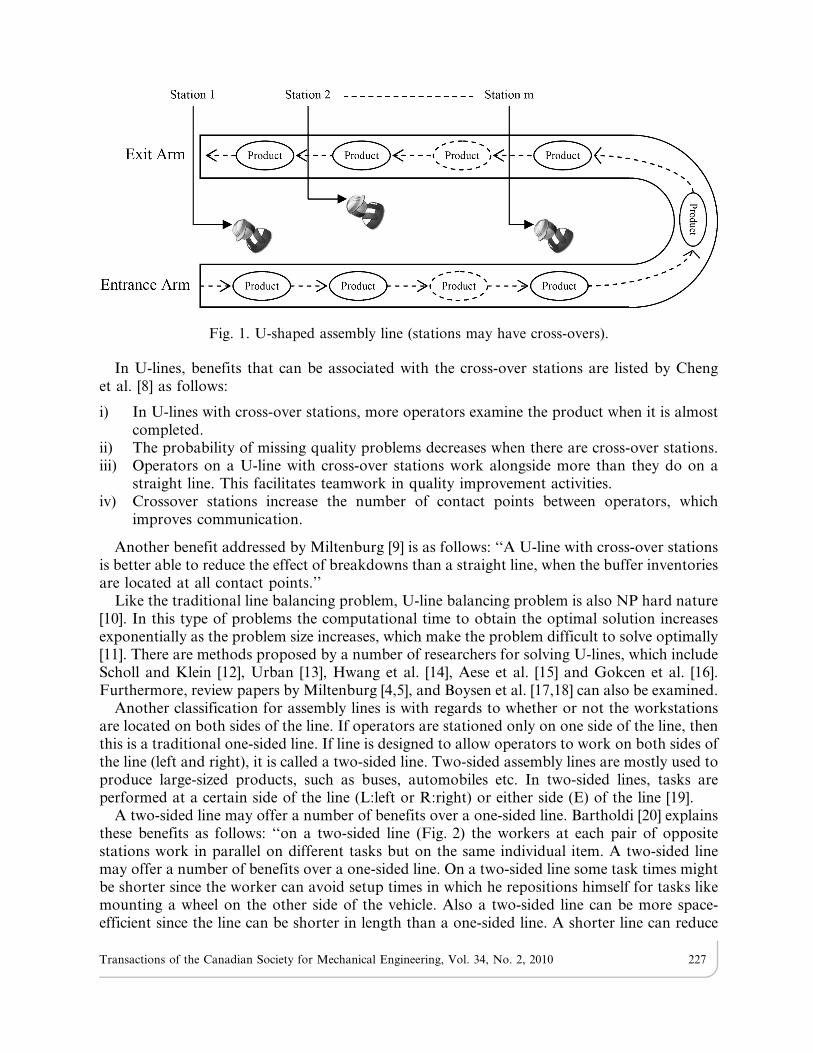
Similarly, this study proposes a new design that combines two-sided lines with U-shapedlines, which enables the two-sided lines to utilize cross-over stations. Fig. 3 demonstrates the pro-posed new design, where stations are positioned both inside and outside the U-shaped line asdescribed in the next section.
3. TWO-SIDED ASSEMBLY LINES WITH ONE SIDE IN U-SHAPE
We propose a new design for assembly lines which offers the advantages of both U-shapedand two-sided lines. New design consists of two sides, one of which is designed in U-shape. Theother side is arranged as a straight line. We name the balancing problem based on this newdesign as Two-sided Assembly Line Balancing with One Side in U-Shape (TALBU).
Our assumptions about TALBU are as follows:
- Operators perform tasks in parallel at both sides of the line.
- Task times are deterministic and independent of the assigned station.
- The travel times of operators are ignored.
- Parallel tasks and parallel stations are not allowed.
In TALBU, one side of the line is considered and balanced as a straight line, while the otherside of the line is treated as a U-shaped line. In two-sided lines, tasks are categorized as being
Fig. 2. Two-sided assembly line.
Transactions of the Canadian Society for Mechanical Engineering, Vol. 34, No. 2, 2010 228
‘Left’, ‘Right’ or ‘Either’. A task categorized as ‘Left’/‘Right’ can only be performed on the left/right side of the line. A task of ‘Either’ type can be performed on any side of the line. Dependingon the direction of product either side of the line can be labelled as left or right. Therefore, aTALBU problem can be solved in two modes: (1) Balance when left side of the line is treated asa U-shaped line; (2) Balance when right side of the line is treated as a U-shaped line. While bothmodes may produce the same results in a given problem, if any of the modes yields a betterbalance over the other, result of that mode can be taken as the best balance.
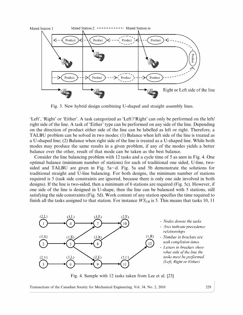
Consider the line balancing problem with 12 tasks and a cycle time of 5 as seen in Fig. 4. Oneoptimal balance (minimum number of stations) for each of traditional one sided, U-line, two-sided and TALBU are given in Fig. 5a,d. Fig. 5a and 5b demonstrate the solutions fortraditional straight and U-line balancing. For both designs, the minimum number of stationsrequired is 5 (task side constraints are ignored, because there is only one side involved in bothdesigns). If the line is two-sided, then a minimum of 6 stations are required (Fig. 5c). However, ifone side of the line is designed in U-shape, then the line can be balanced with 5 stations, stillsatisfying the side constraints (Fig. 5d). Work content of any station specifies the time required tofinish all the tasks assigned to that station. For instance WS2R is 5. This means that tasks 10, 11
Fig. 4. Sample with 12 tasks taken from Lee et al. [23]
Fig. 3. New hybrid design combining U-shaped and straight assembly lines.
Transactions of the Canadian Society for Mechanical Engineering, Vol. 34, No. 2, 2010 229

and 12 are assigned to the second station on the right side of the line that is designed in U-shape,and this station will complete all of these tasks in 5 time units, which is equal to the cycle time.
4. ASSIGNMENT ALGORITHM FOR TALBU
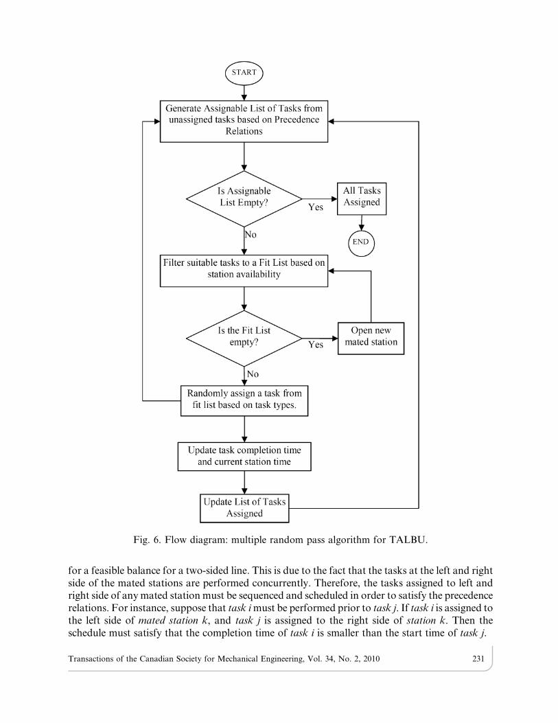
A multiple random pass algorithm has been developed for the new design. Algorithm is ingeneral similar to COMSOAL method developed by Arcus [28], but it also includes schedulingof tasks which is not a part of COMSOAL. A flow diagram describing the algorithm is given inFig. 6. Initially, a list of unassigned tasks, which have no predecessors or successors, isgenerated. Tasks with no successors are only assignable to the exit arm of the U-shaped side.List of assignable tasks are then filtered into a fit list based on station time availability. Fit listtakes also into account the potential scheduling conflicts between left and right side of thecurrent mated station. A task can be assignable based on available station time; however such ascheduling conflict may prevent it entering the fit list. Thus, fit list includes the tasks that haveno predecessors or no successors, that have task times less than or equal to the available stationtime, and that wouldn’t create a scheduling conflict as described in the next paragraph.
4.1. Sequencing and Scheduling Requirement for Two-sided LinesIn a two-sided line, the workstations sharing the same position on the left and right of the line
are referred to as mated stations. There is a need for sequencing and scheduling while searching
Fig. 5. a. Optimal balance (12-task problem) for straight line; side constraints are ignored, b. Optimalbalance (12-task problem) for U-shaped line; side constraints are ignored, c. Optimal balance (12-taskproblem) for Two-sided straight line, d. Optimal balance (12-task problem) for Two-sided line withone side in U-shape.
Transactions of the Canadian Society for Mechanical Engineering, Vol. 34, No. 2, 2010 230
for a feasible balance for a two-sided line. This is due to the fact that the tasks at the left and rightside of the mated stations are performed concurrently. Therefore, the tasks assigned to left andright side of any mated station must be sequenced and scheduled in order to satisfy the precedencerelations. For instance, suppose that task i must be performed prior to task j. If task i is assigned tothe left side of mated station k, and task j is assigned to the right side of station k. Then theschedule must satisfy that the completion time of task i is smaller than the start time of task j.
Fig. 6. Flow diagram: multiple random pass algorithm for TALBU.
Transactions of the Canadian Society for Mechanical Engineering, Vol. 34, No. 2, 2010 231
4.2. Task TypesAssuming Left as the U-shaped side, tasks in fit list can be any of the types given below:
Type 1- Only assignable to Right side due to side constraint,Type 2- Only assignable to Left side due to side constraint,Type 3- Only assignable to Left side (exit arm of U-shape side) due to having no successors,Type 4- Only assignable to Left or Right side depending on available station time (although the
task is of Either type),Type 5- Assignable to any of the sides,
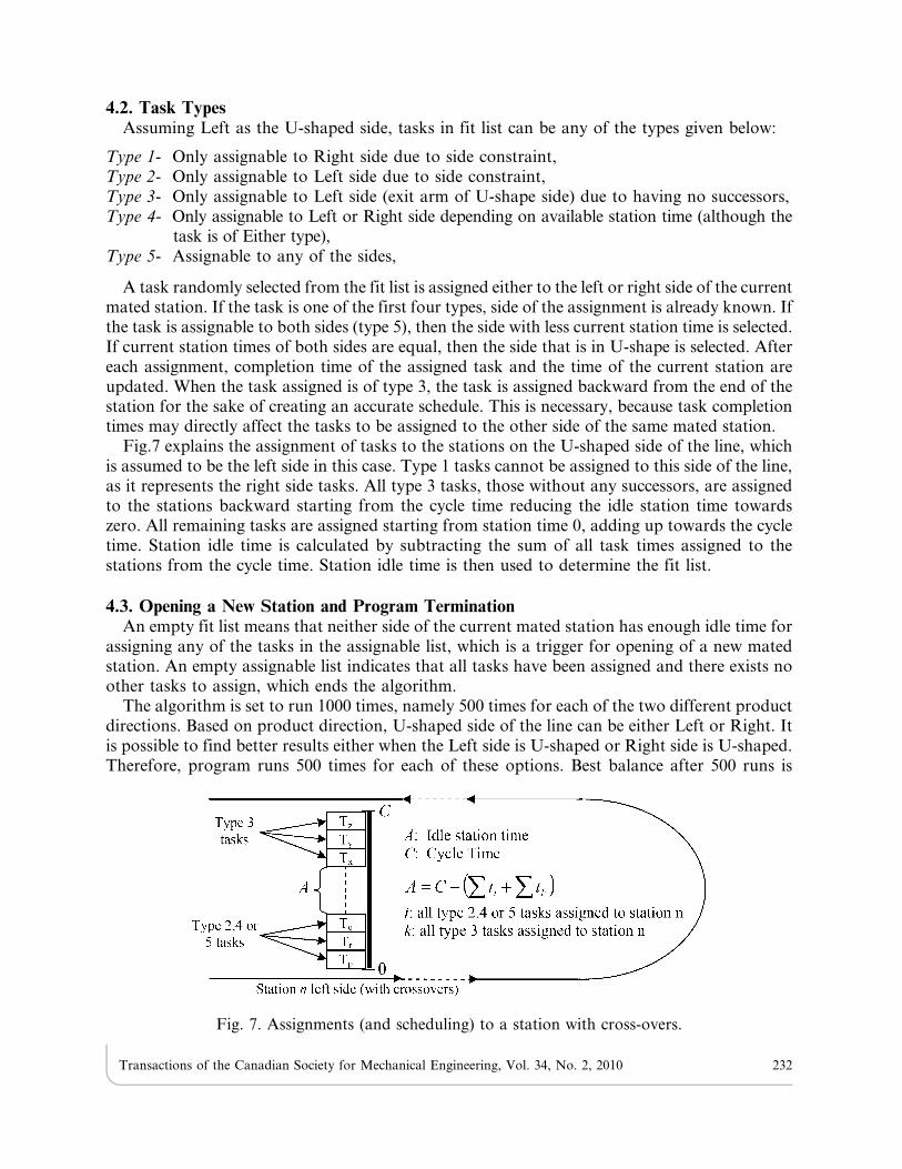
A task randomly selected from the fit list is assigned either to the left or right side of the currentmated station. If the task is one of the first four types, side of the assignment is already known. Ifthe task is assignable to both sides (type 5), then the side with less current station time is selected.If current station times of both sides are equal, then the side that is in U-shape is selected. Aftereach assignment, completion time of the assigned task and the time of the current station areupdated. When the task assigned is of type 3, the task is assigned backward from the end of thestation for the sake of creating an accurate schedule. This is necessary, because task completiontimes may directly affect the tasks to be assigned to the other side of the same mated station.
Fig.7 explains the assignment of tasks to the stations on the U-shaped side of the line, whichis assumed to be the left side in this case. Type 1 tasks cannot be assigned to this side of the line,as it represents the right side tasks. All type 3 tasks, those without any successors, are assignedto the stations backward starting from the cycle time reducing the idle station time towardszero. All remaining tasks are assigned starting from station time 0, adding up towards the cycletime. Station idle time is calculated by subtracting the sum of all task times assigned to thestations from the cycle time. Station idle time is then used to determine the fit list.
4.3. Opening a New Station and Program TerminationAn empty fit list means that neither side of the current mated station has enough idle time for
assigning any of the tasks in the assignable list, which is a trigger for opening of a new matedstation. An empty assignable list indicates that all tasks have been assigned and there exists noother tasks to assign, which ends the algorithm.
The algorithm is set to run 1000 times, namely 500 times for each of the two different productdirections. Based on product direction, U-shaped side of the line can be either Left or Right. Itis possible to find better results either when the Left side is U-shaped or Right side is U-shaped.Therefore, program runs 500 times for each of these options. Best balance after 500 runs is
Fig. 7. Assignments (and scheduling) to a station with cross-overs.
Transactions of the Canadian Society for Mechanical Engineering, Vol. 34, No. 2, 2010 232
taken as the solution for each product direction. If the algorithm reaches the lower bound (LB)at any run, algorithm ends for that product direction. Lower bound is taken simply as (sum oftask times/cycle time) rounded up to the nearest integer.
5. EXPERIMENTAL RESULTS
Proposed algorithm has been applied to known test-bed problems. Algorithm was codedusing Pascal language and run on a computer with a Pentium 2.00 Ghz dual CPU and 2.00 GBmemory. To better explain the algorithm, initial steps and the result of the solution of anumerical example are given in appendix.
Problems are represented by the number of tasks they contain (i.e. the problem with 16 tasksis shown as p16). Problems p9, p12 and p 24, were taken from Kim et al. [24]. Problems p65 andp205 were taken from Lee et al. [23]. Data for p148 is from Bartholdi’s paper [20].
In p148, the processing times of tasks 79 and 108 are much larger than those of the other tasks.Since these impose a limit on cycle time, the processing times are changed from 2.81 to 1.11 andfrom 3.83 to 0.43. In that same problem, there are two precedence relations (55 to 54 and 90 to 79)that violates all-forward precedence network requirement. Accordingly, precedence network wasreconstructed into an all-forward topology.
Problems are solved for different cycle times and results are examined in two groups; small sizeproblems and large size problems. Results for small sized problems are given in Table 1 compared totwo-sided line balancing results of some other researchers. Wu et al.’s [26] model finds the optimalsolution using a branch and bound algorithm. Ozcan and Toklu [29] employ mixed integerprogramming to reach optimal results for small-sized problems. Baykasoglu and Dereli [22] achievenear-optimal results by ant-colony heuristics, Hu et al. [30] proposes an enumerative algorithm.
Two separate solutions exist for TALBU; Left side and Right side. While one represents thecase where Left side of the line is U-shaped and the other takes the Right side as U-shaped side.Solving the small-sized problems using the proposed algorithm yielded optimal results for all cycletimes and for both Left and Right sides consuming a practically short CPU time (max 114 ms).Because the TALBU algorithm terminates after reaching the LB, CPU time required to reach anoptimal solution that is equal to LB can be substantially smaller (4 ms in some cases).
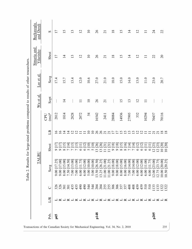
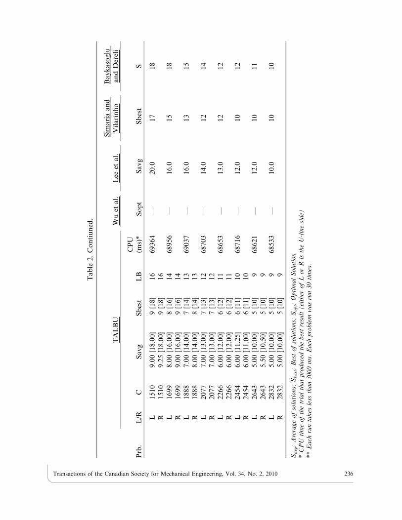
Table 2 gives a comparison of results for large-sized test-bed problems. For large-sizedproblems, it is less probable to achieve the LB with 1000 runs. To increase the probability ofobtaining better results, problems were solved 4 times for each cycle time. Each of the 4 solutionsused different random seeds and set to run 1000 times if the algorithm does not stumble upon theLB at any of the runs. Average and best of the four solutions are also given.
For certain cycle times, optimal results of problems p65 and p148 are given by Wu et al. [26].Proposed algorithm also produced optimal results for the same cycle times with the onlyexception of p148 (C5408). For other cases, where optimal solutions are not known, ourmethod generated better results compared to results of other researchers such as Lee et al. [23],who use a group assignment method; Simaria and Vilarinho [21], who employs ant colonyheuristics; and Baykasoglu and Dereli [22]. Maximum CPU time for p65 is 2828 ms, and forp148 is 28084 ms. In most cases, where algorithm hits the lower bound, CPU time required iseven considerably smaller (min 54 ms for p65 and 332 ms for p148).
Results of p205 are either one or two stations more than the lower bound. Because thealgorithm does not achieve the lower bound, CPU time required for any of these solutions isalmost the same (around 70.000 ms). Simaria and Vilarinho’s [21] algorithm generated betterresults for some cycle times.
Transactions of the Canadian Society for Mechanical Engineering, Vol. 34, No. 2, 2010 233

In order to see whether it is possible to generate the same results with less CPU time, TALBUalgorithm was run for 100 times and 50 times separately instead of 500 times, using single randomseed only, instead of four different random seeds. While 50 runs were not enough to producesimilar results, 100 runs generated the same results successfully, and it only took about 14.000 ms.
6. CONCLUSION
A new hybrid design for assembly lines and a solution algorithm for the related balancingproblem have been introduced in this paper. It aims to benefit from the advantages of U-shapedlines, at the same time carries the features of two-sided lines. While one side of the line isdesigned to enable stations with cross-overs (U-shaped), other side of the line is designed astraditional straight line. Depending on the product direction either Left or Right side of the linecan be designed in U-shape.
Table 1. TALBU results for small-sized problems compared to results of other researchers.
TALBU Wu et al.Baykasogluand Dereli
Xiaofenget al.
Ozcan andToklu
Prb. L/R C S LB CPU (ms) Sopt S S Sopt
p12 L 4 4 [7] 7 4 4 [7] — — —R 4 4 [7] 7L 5 3 [6] 5 60 3 [6] 3 [6] — 3 [6]R 5 3 [5] 5L 6 3 [5] 5 4 3 [5] 3 [5] 3 [5] 3 [5]R 6 3 [5] 5L 7 2 [4] 4 4 2 [4] 2 [4] 2 [4] 2 [4]R 7 2 [4] 4
p16 L 15 3 [6] 6 24 4 [7] — — 4 [6]R 15 3 [6] 6L 18 3 [6] 5 144 3 [6] — — 3 [6]R 18 3 [6] 5L 20 3 [5] 5 86 3 [5] — — 3 [5]R 20 3 [6] 5L 22 2 [4] 4 85 2 [4] — 2 [4] 2 [4]R 22 2 [4] 4
P24 L 25 3 [6] 6 34 3 [6] 3 [6] 3 [6] 3 [6]R 25 3 [6] 6L 30 3 [5] 5 104 3 [5] 3 [5] — 3 [5]R 30 3 [5] 5L 35 2 [4] 4 116 2 [4] 3 [5] — 2 [4]R 35 2 [4] 4L 40 2 [4] 4 7 2 [4] 2 [4] — 2 [4]R 40 2 [4] 4
L/R: Which side of the line is U-shaped; LB: Lower boundC: Cycle time; Sopt: Optimal solutionS: SolutionM[N]: M is the number of mated stations, N is the number of all stations.
Transactions of the Canadian Society for Mechanical Engineering, Vol. 34, No. 2, 2010 234
Tab
le2.
Res
ult
sfo
rla
rge-
size
dp
rob
lem
sco
mp
are
dto
resu
lts
of
oth
erre
searc
her
s.
TA
LB
UW
uet
al.
Lee
etal.
Sim
ari
aan
dV
ilari
nh
oB
ayk
aso
glu
an
dD
erel
i
Prb
.L
/RC
Savg
Sb
est
LB
CP
U(m
s)*
So
pt
Savg
Sb
est
S
p65
L326
9.0
0[1
7.2
5]
9[1
7]
16
2812
—17.4
17
17
R326
9.0
0[1
7.0
0]
9[1
7]
16
L381
8.0
0[1
5.0
0]
8[1
5]
14
1814
14
15.7
14
15
R381
7.5
0[1
4.5
0]
7[1
4]
14
L435
7.0
0[1
3.0
0]
7[1
3]
12
2828
—13.4
13
13
R435
7.0
0[1
3.0
0]
7[1
3]
12
L490
6.0
0[1
1.7
5]
6[1
1]
11
2072
11
12.0
12
12
R490
6.0
0[1
2.0
0]
6[1
2]
11
L544
5.0
0[1
0.0
0]
5[1
0]
10
54
10
10.6
10
10
R544
5.0
0[1
0.0
0]
5[1
0]
10
p148
L204
13.5
0[2
6.5
0]
13
[26]
26
16542
26
27.0
26
26
R204
13.2
5[2
6.2
5]
13
[26]
26
L255
11.0
0[2
1.0
0]
11
[21]
21
2411
21
21.0
21
21
R255
11.0
0[2
1.2
5]
11
[21]
21
L306
9.0
0[1
8.0
0]
9[1
8]
17
28084
—18.0
18
18
R306
9.0
0[1
8.0
0]
9[1
8]
17
L357
8.0
0[1
5.0
0]
8[1
5]
15
14936
15
15.0
15
15
R357
8.0
0[1
6.0
0]
8[1
6]
15
L408
7.0
0[1
4.0
0]
7[1
4]
13
27995
13
14.0
14
14
R408
7.0
0[1
4.0
0]
7[1
4]
13
L459
6.0
0[1
2.0
0]
6[1
2]
12
332
12
13.0
12
12
R459
6.0
0[1
2.0
0]
6[1
2]
12
L510
6.0
0[1
1.0
0]
6[1
1]
11
10294
11
11.0
11
11
R510
6.0
0[1
1.7
5]
6[1
1]
11
p205
L1133
12.0
0[2
3.0
0]
12
[23]
21
70437
—23.0
22
24
R1133
12.7
5[2
3.7
5]
12
[23]
21
L1322
10.0
0[2
0.0
0]
10
[20]
18
70116
—20.7
20
22
R1322
10.5
0[2
0.2
5]
10
[20]
18
Transactions of the Canadian Society for Mechanical Engineering, Vol. 34, No. 2, 2010 235
TA
LB
UW
uet
al.
Lee
etal.
Sim
ari
aan
dV
ilari
nh
oB
ayk
aso
glu
an
dD
erel
i
Prb
.L
/RC
Savg
Sb
est
LB
CP
U(m
s)*
So
pt
Savg
Sb
est
S
L1510
9.0
0[1
8.0
0]
9[1
8]
16
69364
—20.0
17
18
R1510
9.2
5[1
8.0
0]
9[1
8]
16
L1699
8.0
0[1
6.0
0]
8[1
6]
14
68956
—16.0
15
18
R1699
9.0
0[1
6.0
0]
9[1
6]
14
L1888
7.0
0[1
4.0
0]
7[1
4]
13
69037
—16.0
13
15
R1888
8.0
0[1
4.0
0]
8[1
4]
13
L2077
7.0
0[1
3.0
0]
7[1
3]
12
68703
—14.0
12
14
R2077
7.0
0[1
3.0
0]
7[1
3]
12
L2266
6.0
0[1
2.0
0]
6[1
2]
11
68653
—13.0
12
12
R2266
6.0
0[1
2.0
0]
6[1
2]
11
L2454
6.0
0[1
1.2
5]
6[1
1]
10
68716
—12.0
10
12
R2454
6.0
0[1
1.0
0]
6[1
1]
10
L2643
5.0
0[1
0.0
0]
5[1
0]
968621
—12.0
10
11
R2643
5.5
0[1
0.5
0]
5[1
0]
9L
2832
5.0
0[1
0.0
0]
5[1
0]
968533
—10.0
10
10
R2832
5.0
0[1
0.0
0]
5[1
0]
9
Savg:Averageofsolutions;
Sbest:Bestofsolutions;
Sopt:OptimalSolution
*CPU
timeofthetrialthatproducedthebestresult(either
ofL
orR
istheU-lineside)
**Each
runtakes
less
than3000ms.Each
problem
wasrun30times.
Tab
le2.
Co
nti
un
ed.
Transactions of the Canadian Society for Mechanical Engineering, Vol. 34, No. 2, 2010 236
This study proposes a multi-pass random assignment line balancing algorithm aiming atminimizing the number of stations. Algorithm also determines the sequence and the schedule ofthe tasks. Two different balances (number of stations) may exist based on whether Left or Rightside of the line has the U-shaped design, smaller of which can be taken as the line design.
Algorithm was tested on several small and large sized problems and different cycle times.Results are promising for both small and large sized problems. TALBU can be balancedoptimally in a considerably low CPU time for small-sized problems. For some instances, it iseven possible to improve optimal solutions of two-sided line problems thanks to the new hybriddesign. Solutions to large-sized problems as well yielded optimal solutions in most of the casesusing reasonable CPU times. For cases, where optimal solutions were not achieved, results werestill equally comparable to findings of other studies dealing with two-sided lines.
Although the new design has the potential to produce a balance with fewer stations, it mayrequire more space due to the U-shape on one side. Trade-off between increased spacerequirements and reduced number of stations along with other benefits of U-shaped linesshould be taken into consideration.
Novel hybrid design of TALBU may offer manufacturers a new perspective in designingassembly lines. Other forms of hybrid assembly line designs can also be generated such as U-shaped lines with two sides. Proposed TALBU algorithm, which uses random assignment, canbe improved especially for large-sized problems using meta-heuristic approaches.
ACKNOWLEDGMENTS
We would like to thank all the referees, who have added value to our paper with theirthorough reviews and recommendations.
REFERENCES
1. Ozcan, U., Gokcen, H., Toklu, B., ‘‘Balancing parallel two-sided assembly lines,’’ International
Journal of Production Research, First published on: 04 August 2009, doi: 10.1080/002075409030749912009.
2. Miltenburg, J., ‘‘Balancing U-lines in a multiple U-line facility,’’ European Journal of Operational
Research, Vol. 109, No. 1, pp. 1–23, 1998.
3. Miltenburg, G.J., Wijngaard, J., ‘‘The U-line line balancing problem,’’ Management Science,
Vol. 40, No. 10, pp. 1378–1388, 1994.
4. Miltenburg, J., ‘‘One-piece flow manufacturing on U-shaped production lines: A tutorial,’’ IIE
Transactions (Institute of Industrial Engineers), Vol. 33, No. 4, pp. 303–321, 2001.
5. Miltenburg, J., ‘‘U-shaped production lines: A review of theory and practice,’’ International
Journal of Production Economics, Vol. 70, No. 3, pp. 201–214, 2001.
6. Monden, Y., ‘‘Toyota production system: practical approach to production management,’’Industrial Engineering and Management Press, Institute of Industrial Engineers, Norcross, GA,1983.
7. Aase, G.R., Olson, J.R., Schniederjans, M.J., ‘‘U-shaped assembly line layouts and their impact onlabor productivity: An experimental study,’’ European Journal of Operational Research, Vol. 156,No. 3, pp. 698–711, 2004.
8. Cheng, C.H., Miltenburg, J., Motwani, J., ‘‘The effect of straight- and u-shaped lines onquality,’’ IEEE Transactions on Engineering Management, Vol. 47, No. 3, pp. 321–334, 2000.
Transactions of the Canadian Society for Mechanical Engineering, Vol. 34, No. 2, 2010 237
9. Miltenburg, J., ‘‘The effect of breakdowns on U-shaped production lines,’’ International Journal
of Production Research, Vol. 38, No. 2, pp. 353–364, 2000.
10. Sparling, D., Miltenburg, J., ‘‘The mixed-model U-line balancing problem,’’ International
Journal of Production Research, Vol. 36, No. 2, pp. 485–501, 1998.
11. Gokcen, H., Agpak, K., ‘‘A goal programming approach to simple U-line balancing problem,’’
European Journal of Operational Research, Vol. 171, No. 2, pp. 577–585, 2006.
12. Scholl, A., Klein, R., ‘‘ULINO: optimally balancing U-shaped JIT assembly lines,’’
International Journal of Production Research, Vol. 37, No. 4, pp. 721–736, 1999.
13. Urban, T.L., ‘‘Optimal balancing of U-shaped assembly lines,’’ Management Science, Vol. 44,
No. 5, pp. 738–741, 1998.
14. Hwang, R.K., Katayama, H., Gen, M., ‘‘U-shaped assembly line balancing problem with genetic
algorithm,’’ International Journal of Production Research, Vol. 46, No. 16, pp. 4637–4649, 2008.
15. Aase, G.R., Schniederjans, M.J., Olson, J.R., ‘‘U-OPT: An analysis of exact U-shaped line balancingprocedures,’’ International Journal of Production Research, Vol. 41, No. 17, pp. 4185–4210, 2003.
16. Gokcen, H., Agpak, K., Gencer, C., Kizilkaya, E., ‘‘A shortest route formulation of simpleU-type assembly line balancing problem,’’ Applied Mathematical Modelling, Vol. 29, No. 4,
pp. 373–380, 2005.
17. Boysen, N., Fliedner, M., Scholl, A., ‘‘A classification of assembly line balancing problems,’’
European Journal of Operational Research, Vol. 183, No. 2, pp. 674–93, 2007.
18. Boysen, N., Fliedner, M., Scholl, A., ‘‘Assembly line balancing: Which model to use when?’’
International Journal of Production Economics, Vol. 111, No. 2, pp. 509–528, 2008.
19. Ozcan, U., Toklu, B., ‘‘Balancing of mixed-model two-sided assembly lines,’’ Computers &
Industrial Engineering, Vol. 57, No. 1, pp. 217–227, 2009.
20. Bartholdi, J.J., ‘‘Balancing two-sided assembly lines: a case study,’’ International Journal of
Production Research, Vol. 31, No. 10, pp. 2447, 1993.
21. Simaria, A.S., Vilarinho, P.M., ‘‘2-ANTBAL: An ant colony optimisation algorithm for balancingtwo-sided assembly lines,’’ Computers & Industrial Engineering, Vol. 56, No. 2, pp. 489–506, 2009.
22. Baykasoglu, A., Dereli, T., ‘‘Two-sided assembly line balancing using an ant-colony-basedheuristic,’’ International Journal of Advanced Manufacturing Technology, Vol. 36, No. 5–6, pp.
582–588, 2008.
23. Lee, T.O., Kim, Y., Kim, Y.K., ‘‘Two-sided assembly line balancing to maximize work relatednessand slackness,’’ Computers & Industrial Engineering, Vol. 40, No. 3, pp. 273–292, 2001.
24. Kim, Y.K., Song, W.S., Kim, J.H., ‘‘A mathematical model and a genetic algorithm for two-sidedassembly line balancing,’’ Computers and Operations Research, Vol. 36, No. 3, pp. 853–865, 2009.
25. Kim, Y.K., Kim, Y., Kim, Y.J., ‘‘Two-sided assembly line balancing: a genetic algorithmapproach,’’ Production Planning and Control, Vol. 11, No. 1, pp. 44–53, 2000.
26. Wu, E.F., Jin, Y., Bao, J.S., Hu, X.F., ‘‘A branch-and-bound algorithm for two-sided assemblyline balancing,’’ International Journal of Advanced Manufacturing Technology, Vol. 39, No. 9–10,
pp. 1009–1015, 2008.
27. Lapierre, S.D., Ruiz, A.B., ‘‘Balancing assembly lines: an industrial case study,’’ The Journal of
the Operational Research Society, Vol. 55, No. 6, pp. 589, 2004.
28. Arcus, A.L., ‘‘COMSOAL: A Computer Method of Sequencing Operations for AssemblyLines,’’ International Journal of Production Research, Vol. 4, No. 4, pp. 259–277, 1966.
29. Ozcan, U., Toklu, B., ‘‘Multiple-criteria decision-making in two-sided assembly line balancing:A goal programming and a fuzzy goal programming models,’’ Computers & Operations Research,
Vol. 36, No. 6, pp. 1955–1965, 2009.
30. Hu, X., Wu, E., Jin, Y., ‘‘A station-oriented enumerative algorithm for two-sided assembly line
balancing,’’ European Journal of Operational Research, Vol. 186, No. 1, pp. 435, 2008.
Transactions of the Canadian Society for Mechanical Engineering, Vol. 34, No. 2, 2010 238
APPENDIX
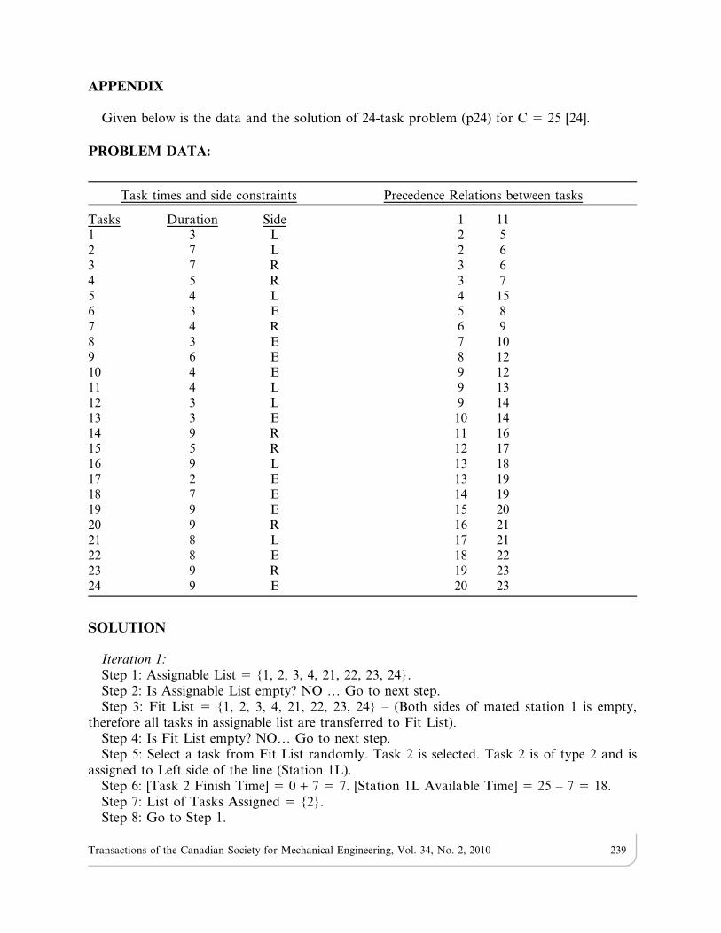
Given below is the data and the solution of 24-task problem (p24) for C 5 25 [24].
PROBLEM DATA:
SOLUTION
Iteration 1:Step 1: Assignable List 5 {1, 2, 3, 4, 21, 22, 23, 24}.Step 2: Is Assignable List empty? NO … Go to next step.Step 3: Fit List 5 {1, 2, 3, 4, 21, 22, 23, 24} – (Both sides of mated station 1 is empty,
therefore all tasks in assignable list are transferred to Fit List).Step 4: Is Fit List empty? NO… Go to next step.Step 5: Select a task from Fit List randomly. Task 2 is selected. Task 2 is of type 2 and is
assigned to Left side of the line (Station 1L).Step 6: [Task 2 Finish Time] 5 0 + 7 5 7. [Station 1L Available Time] 5 25 – 7 5 18.Step 7: List of Tasks Assigned 5 {2}.Step 8: Go to Step 1.
Task times and side constraints Precedence Relations between tasks
Tasks Duration Side 1 111 3 L 2 52 7 L 2 63 7 R 3 64 5 R 3 75 4 L 4 156 3 E 5 87 4 R 6 98 3 E 7 109 6 E 8 1210 4 E 9 1211 4 L 9 1312 3 L 9 1413 3 E 10 1414 9 R 11 1615 5 R 12 1716 9 L 13 1817 2 E 13 1918 7 E 14 1919 9 E 15 2020 9 R 16 2121 8 L 17 2122 8 E 18 2223 9 R 19 2324 9 E 20 23
Transactions of the Canadian Society for Mechanical Engineering, Vol. 34, No. 2, 2010 239
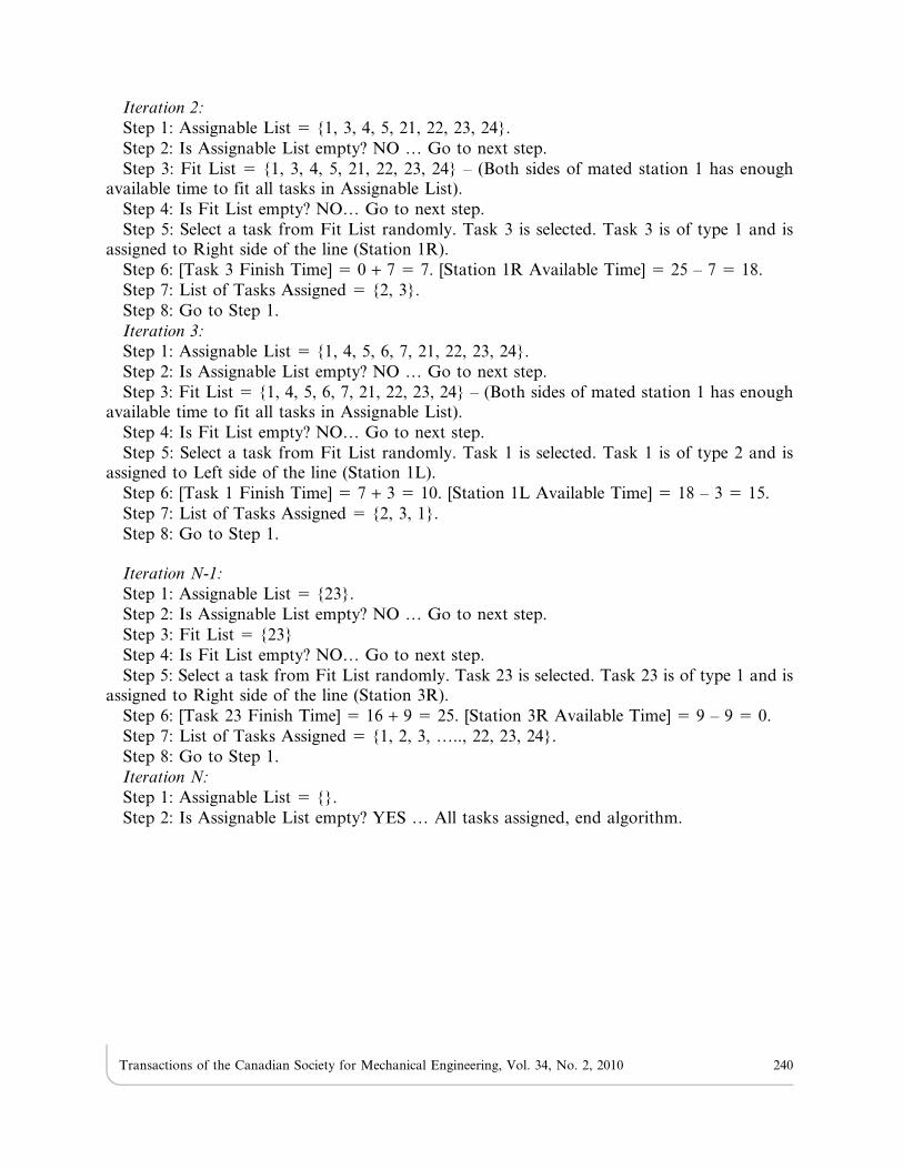
Iteration 2:
Step 1: Assignable List 5 {1, 3, 4, 5, 21, 22, 23, 24}.
Step 2: Is Assignable List empty? NO … Go to next step.
Step 3: Fit List 5 {1, 3, 4, 5, 21, 22, 23, 24} – (Both sides of mated station 1 has enoughavailable time to fit all tasks in Assignable List).
Step 4: Is Fit List empty? NO… Go to next step.
Step 5: Select a task from Fit List randomly. Task 3 is selected. Task 3 is of type 1 and isassigned to Right side of the line (Station 1R).
Step 6: [Task 3 Finish Time] 5 0 + 7 5 7. [Station 1R Available Time] 5 25 – 7 5 18.
Step 7: List of Tasks Assigned 5 {2, 3}.
Step 8: Go to Step 1.
Iteration 3:
Step 1: Assignable List 5 {1, 4, 5, 6, 7, 21, 22, 23, 24}.
Step 2: Is Assignable List empty? NO … Go to next step.
Step 3: Fit List 5 {1, 4, 5, 6, 7, 21, 22, 23, 24} – (Both sides of mated station 1 has enoughavailable time to fit all tasks in Assignable List).
Step 4: Is Fit List empty? NO… Go to next step.
Step 5: Select a task from Fit List randomly. Task 1 is selected. Task 1 is of type 2 and isassigned to Left side of the line (Station 1L).
Step 6: [Task 1 Finish Time] 5 7 + 3 5 10. [Station 1L Available Time] 5 18 – 3 5 15.
Step 7: List of Tasks Assigned 5 {2, 3, 1}.
Step 8: Go to Step 1.
Iteration N-1:
Step 1: Assignable List 5 {23}.
Step 2: Is Assignable List empty? NO … Go to next step.
Step 3: Fit List 5 {23}
Step 4: Is Fit List empty? NO… Go to next step.
Step 5: Select a task from Fit List randomly. Task 23 is selected. Task 23 is of type 1 and isassigned to Right side of the line (Station 3R).
Step 6: [Task 23 Finish Time] 5 16 + 9 5 25. [Station 3R Available Time] 5 9 – 9 5 0.
Step 7: List of Tasks Assigned 5 {1, 2, 3, ….., 22, 23, 24}.
Step 8: Go to Step 1.
Iteration N:
Step 1: Assignable List 5 {}.
Step 2: Is Assignable List empty? YES … All tasks assigned, end algorithm.
Transactions of the Canadian Society for Mechanical Engineering, Vol. 34, No. 2, 2010 240
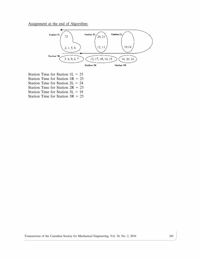
Assignment at the end of Algorithm:
Station Time for Station 1L 5 25Station Time for Station 1R 5 25Station Time for Station 2L 5 24Station Time for Station 2R 5 23Station Time for Station 3L 5 18Station Time for Station 3R 5 25
Transactions of the Canadian Society for Mechanical Engineering, Vol. 34, No. 2, 2010 241