a network topology description model for grid application - hal
TRANSCRIPT
HAL Id: inria-00070773https://hal.inria.fr/inria-00070773
Submitted on 19 May 2006
HAL is a multi-disciplinary open accessarchive for the deposit and dissemination of sci-entific research documents, whether they are pub-lished or not. The documents may come fromteaching and research institutions in France orabroad, or from public or private research centers.
L’archive ouverte pluridisciplinaire HAL, estdestinée au dépôt et à la diffusion de documentsscientifiques de niveau recherche, publiés ou non,émanant des établissements d’enseignement et derecherche français ou étrangers, des laboratoirespublics ou privés.
A Network Topology Description Model for GridApplication Deployment
Sébastien Lacour, Christian Pérez, Thierry Priol
To cite this version:Sébastien Lacour, Christian Pérez, Thierry Priol. A Network Topology Description Model for GridApplication Deployment. [Research Report] RR-5221, INRIA. 2004, pp.22. <inria-00070773>

ISS
N 0
249-
6399
ISR
N IN
RIA
/RR
--52
21--
FR
+E
NG
ap por t de r ech er ch e
Thème NUM
INSTITUT NATIONAL DE RECHERCHE EN INFORMATIQUE ET EN AUTOMATIQUE
A Network Topology Description Modelfor Grid Application Deployment
Sébastien Lacour — Christian Pérez — Thierry Priol
N° 5221
June 3rd, 2004

Unité de recherche INRIA RennesIRISA, Campus universitaire de Beaulieu, 35042 Rennes Cedex (France)
Téléphone : +33 2 99 84 71 00 — Télécopie : +33 2 99 84 71 71
A Network Topology Description Modelfor Grid Application Deployment
Sébastien Lacour, Christian Pérez, Thierry Priol�
Thème NUM — Systèmes numériquesProjet Paris
Rapport de recherche n° 5221 — June 3rd, 2004 — 22 pages
Abstract: Computational grids are probably among the most heterogeneous computing sys-tems. However, they are very attractive for their potential computational power. Theirheterogeneity is especially perceptible during the deployment of grid applications. In par-ticular, an automatic and efficient deployment of grid applications on resources requires tohave access to the characteristics of the resources. This paper presents a description modelof (grid) networks which provides a synthetic view of the network topology. The simplic-ity of the proposed model does not hinder the description of complex network topologies(asymmetric links, firewalls, non-IP networks, non-hierarchical topologies).
Key-words: Grid Information Service, Network Topology, Description Model, Grid Re-source Description, Constrained Application Deployment.
�
{Sebastien.Lacour,Christian.Perez,Thierry.Priol}@irisa.fr

Modèle de description de topologie réseaupour le déploiement d’applications
sur grille de calculRésumé : Les grilles de calcul font probablement partie des infrastructures de calcul lesplus hétérogènes. Cependant, leur puissance potentielle de calcul présente un intérêt incon-testable. L’hétérogénéité des grilles de calcul se manifeste en particulier au moment dudéploiement d’applications sur la grille. Plus précisément, un déploiement automatiqueet efficace d’applications sur grille de calcul nécessite de connaître les caractéristiques desressources de la grille. Ce papier présente un modèle de description de réseau (de grillede calcul) qui offre une vision synthétique de la topologie du réseau de communication.La simplicitié du modèle proposé permet néanmoins la description de topologies réseaucomplexes (liens asymétriques, pare-feux, réseaux non IP, topologies non hiérarchiques).
Mots-clés : Service d’information sur la grille, topologie réseau, modèle de description deressources, description de ressources de grille de calcul, déploiement d’applications souscontraintes.
A Network Topology Description Model for Grid Application Deployment 3
1 IntroductionComputational grids are probably the most heterogeneous computing systems: they can bemade of computers with different operating systems, various hardware and software, dif-ferent storage capacities, CPU speeds, network connectivities and technologies. Althoughcomputational grids are attractive for their potential computational power, there are stilldifficulties to exploit such highly heterogeneous resources. Deployment is a very importantphase as it bridges the gap between the user (the application) and the grid (the resources).The first step of the deployment phase consists in selecting a set of resources (includingcomputers and network connections) satisfying constraints imposed by the application; inthe second step, the application is launched on the selected resources [24]. The first step isa difficult part of application deployment. Ideally, deployment should be as automatic aspossible: a user should not have to manually select resources. He or she should just have tospecify the application’s requirements. In order to achieve automatic deployment, the char-acteristics of both the resources and the constraints of the application need to be describedprecisely to allow for better, automatic resource selection.
Accurate information about compute nodes, installed software, network connectivityand performance properties is required [39] for a pertinent deployment. Previous workssucceed in describing properly the compute nodes (CPU speed, memory size, operatingsystem, etc.), but generally fail to describe the network topology and its characteristics in asimple, synthetic, and complete way.
This paper presents a network topology description model for computational grids. We targetboth simple and complex grids, such as those currently deployed (the Grid Physics Net-work, GriPhyN [20], or TeraGrid [42]), as well as any grid which can be devised. For exam-ple, the model should include network connectivity information and support not purelyhierarchical networks, asymmetric links, firewalls.
The rest of this paper is divided as follows. Section 2 presents some examples of real-world grid network topologies which we need to be able to describe. The related workwith respect to network description is analyzed in Section 3. Our model of a grid networktopology description is introduced in Section 4 and an implementation which extends theMDS2 module of the Globus Toolkit is presented in Section 5. Section 6 concludes thepaper.
2 Grid NetworksBefore deploying the processes of a distributed application on a grid, the compute nodes onwhich the application will be run must be selected. This node selection can be constrainedby both user-level and application-level requirements. A user-level constraint is used forthe user’s comfort, such as “I want this application to run in less than two hours.” Anapplication-level constraint is a requirement imposed by the application developer, like“this application needs 1 GB of memory.”
RR n° 5221

4 Sébastien Lacour, Christian Pérez, Thierry Priol
���
���switch
��� ���
��switchInternet
��
router
router
Figure 1: Grid A: a simple grid made of two Fast-Ethernet clusters.
Then, the user-level and application-level constraints must be translated into computer-level and network-level queries. Ideally, this translation process should be automatic, mix-ing user-level and application-level constraints as well as information on the behavior ofthe application: this very difficult problem is not the focus of this paper. The computerand network description must make it possible to satisfy such compute-level and network-level queries as “I want 32 computers connected by a Myrinet-2000 network” or “I want 32computers connected by a network of at least 1 Gb/s, distant from the visualization host ofIP a.b.c.d by at most 5 ms of latency”.
Note that the process of automatically selecting the resources which will execute theapplication to deploy, i.e. mapping the processes onto the compute nodes of a grid, hasalready been studied and is out of the scope of this paper: see the work done by the ICENIproject [17, 16], Sekitei [23], Condor’s matchmaking [36] and an extension [25], or [30] foralgorithms which dynamically remap the subtasks of a running application.
Note also that we do not address the issue of feeding the grid information service (GIS)automatically, or monitoring the network. The network description might be entered man-ually by administrators at distributed grid sites, or automatically by some monitoring tool(see subsections 3.4 and 3.8, as well as [6, 11]).
The network must be described accurately enough to answer these queries, and the or-ganization of the information must make it as easy as possible to satisfy them. As the prop-erties of the compute nodes of a grid are usually described properly and accurately (seeSection 3), this paper focuses on the description of the network topology, and this sectionpresents only examples of real-world grid network topologies which we need to be ableto describe. However, we keep in mind that realistic queries are made of both networkconstraints and computer constraints.
2.1 Simple GridsFigure 1 shows the physical description of a simple grid (Grid A), made of two Fast-Ethernet clusters connected together through the Internet. Each cluster is made of threehosts (
���). The description of such a grid should be as simple as the grid itself.
INRIA
A Network Topology Description Model for Grid Application Deployment 5
switchFastEth. ��
� �Gigabitswitch
� �
���
switchFastEth.
Internet
Cluster A
Cluster BMyrinetswitch
router
router
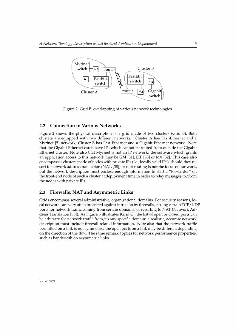
Figure 2: Grid B: overlapping of various network technologies.
2.2 Connection to Various NetworksFigure 2 shows the physical description of a grid made of two clusters (Grid B). Bothclusters are equipped with two different networks. Cluster A has Fast-Ethernet and aMyrinet [5] network; Cluster B has Fast-Ethernet and a Gigabit Ethernet network. Notethat the Gigabit Ethernet cards have IPs which cannot be routed from outside the GigabitEthernet cluster. Note also that Myrinet is not an IP network: the software which grantsan application access to this network may be GM [31], BIP [35] or MX [32]. This case alsoencompasses clusters made of nodes with private IPs (i.e., locally valid IPs), should they re-sort to network address translation (NAT, [38]) or not: routing is not the focus of our work,but the network description must enclose enough information to start a “forwarder” onthe front-end node of such a cluster at deployment time in order to relay messages to/fromthe nodes with private IPs.
2.3 Firewalls, NAT and Asymmetric LinksGrids encompass several administrative, organizational domains. For security reasons, lo-cal networks are very often protected against intrusion by firewalls, closing certain TCP/UDPports for network traffic coming from certain domains, or resorting to NAT (Network Ad-dress Translation [38]). As Figure 3 illustrates (Grid C), the list of open or closed ports canbe arbitrary for network traffic from/to any specific domain: a realistic, accurate networkdescription must include firewall-related information. Note also that the network trafficpermitted on a link is not symmetric: the open ports on a link may be different dependingon the direction of the flow. The same remark applies for network performance properties,such as bandwidth on asymmetric links.
RR n° 5221

6 Sébastien Lacour, Christian Pérez, Thierry Priol
Internet
Domain A Domain B
Domain CUDP: port 450TCP: ports [11, 71]
no port
all portsport 22
UDP: all ports; TCP: port 80
ports[9, 11]
� [21, 31]
Figure 3: Grid C: firewalls limiting network traffic selectively.
switch switch
� � � �
switch
switch
� �
��
� �
���switch
switch
InternetLANCampus
privatenetwork
Figure 4: Grid D: non-hierarchical network.
2.4 Non-Hierarchical Network TopologiesFigure 4 shows an example of non-hierarchical network (Grid D). This network is madeof three Fast-Ethernet clusters. Two clusters only are connected to the Internet. Anotherpair of clusters is connected through a private, dedicated high-performance network. Twoclusters are located in the same institute, connected over a Local-Area Network (LAN).This network configuration is complex, but it is realistic (the authors actually have accessto a similar platform), so the network description must be able to represent a grid such asGrid D.
INRIA

A Network Topology Description Model for Grid Application Deployment 7
2.5 Heterogeneous Network DescriptionTo put it in a nutshell, a useful, relevant network description must include the followingthree pieces of information.
• First, network topology must describe which computers are connected with each otherthrough a particular network, along with the firewalls, and allowing non-hierarchicaltopologies.
• Second, the numerical network performance characteristics must be provided, in terms ofbandwidth (maximum, average, etc.), latency, jitter, loss, etc.
• Third, the resource description must include the various network software or driverswhich enable an application to access a particular (potentially non-IP) network tech-nology, such as Myrinet [5].
This paper focuses on the first aspect of network description, i.e. network topology.
3 Related WorkThe issue of describing networks and grid resources has already been tackled. But newchallenges arise with grids: grid network topologies are not limited to the Internet topol-ogy, including firewalls, non-IP networks, non-hierarchical topologies, where some com-puters cannot communicate directly with certain others. Grid networks must be describedin a scalable (likely distributed) manner and with enough accuracy for a relevant deploy-ment, including network software. Approaches based on a per link description miss syn-thetic, functional topology information. As this synthetic information is usually neededduring the deployment phase [39], it must often be computed. However, this resource con-suming computation can be avoided if the information service directly provides a syntheticview of the network topology.
3.1 Globus MDSMDS (Monitoring and Discovery Service, [12]) is the Grid Information Service (GIS) of theGlobus Toolkit [18]. MDS allows for flexible, hierarchical, distributed (scalable), extensibleinformation storage; it is based on an LDAP directory. MDS includes robust authenticationand authorization mechanisms. MDS also supports dynamic sources of information, suchas the Network Weather Service (NWS, [44, 40]).
MDS describes the compute nodes of a grid conveniently and accurately (CPU speedand number, memory size, disk space, operating system type and version, etc.), but it doesnot currently describe network interconnections between computers. Neither does MDShold information about the network performance properties between the nodes of a grid.
RR n° 5221

8 Sébastien Lacour, Christian Pérez, Thierry Priol
3.2 RSD from ZIBRSD (Resource Service Description, [7, 22]) is “a software architecture for specifying, reg-istering, requesting and accessing resources and services in complex heterogeneous com-puting environments.” It is developed at Konrad-Zuse-Zentrum für Informationstechnikin Berlin (ZIB).
RSD allows for dynamically changing performance data of the network resources and itis not restricted to IP networks. RSD seems to be able to describe any network topology byspecifying each physical network link between any individual computer, router or switchon a pairwise basis. However, RSD is designed for purely hierarchical network topologies,so RSD is ill-suited to represent Grid D presented in Subsection 2.4. RSD does not eithertake firewalls into account, and its description of each physical link may not be scalable ina grid environment.
3.3 The NMWG of the GGFThe Network Measurement Working Group (NMWG, [28]) of the Global Grid Forum (GGF)provides a sound, interoperable way of describing network performance characteristics,but their work does not focus on network topology description. The proposed recommen-dation [26] shows a good work on the classification of network characteristics and mea-surement methodologies, but it does not specify anything precise about network topologydescription, while topology description should come before network characteristics de-scription. The NMWG only considers nodes and paths, providing too many details on thephysical connectivity without discussing scalability in a grid environment: for applicationdeployment, we need a higher-level, logical topology description of a grid.
However, our network topology description model and the performance characteristicsdescription proposed by the NMWG are complementary.
3.4 RemosRemos (REsource MOnitoring System, [27]) is a piece of software which allows network-aware applications to obtain relevant network information. Remos represents the logicalnetwork topology using a graph. The nodes of the graph are the computers, and the edgesare the network links. Remos automatically derives the topology of IP-based Local-AreaNetworks by performing network performance measurements: Remos is concerned onlywith LANs, not grids. Remos does not take firewalls into account, and it is restricted to IPnetworks.
3.5 GridLabMDSGridLab [1] is a project which aims to provide new capabilities for applications to exploitthe power of grid computing. GridLab relies on Globus/MDS (see Subsection 3.1) andstates that the bare MDS system lacks information about network and installed software [2].
INRIA

A Network Topology Description Model for Grid Application Deployment 9
GridLabMDS [3] extends Globus/MDS to describe available software and firewalls byspecifying the open ports on each host. But this is not enough to describe the grid networkprecisely: a firewall can be open or closed with respect to specific domains, while GridLabMDScannot describe this sort of firewall. Neither does GridLabMDS hold information about thenetwork topology or the nature of the network links.
3.6 ENV and GridML from SDSCENV (Effective Network Views, [37]) is a project developed at San Diego SupercomputerCenter (SDSC). ENV uses an XML dialect (GridML, [19]) to describe a network. This soft-ware can represent clusters of computers connected over IP networks only within Local-Area Networks (LANs). Thus, it is not adapted to describe computational grids. GridMLalso assumes purely hierarchical network topologies only, it does not take firewalls intoaccount and it is restricted to IP networks.
3.7 GridG and RGIS Relational DatabaseGridG [29] is a grid network topology generator useful to realistically simulate the re-sources of a grid and designed to evaluate middleware systems for computational grids.However, GridG only considers purely hierarchical IP-based networks. GridG does noteither take firewalls into account.
RGIS [14] is a Relational Grid Information Service system based on a relational database.This approach allows composition of information (“joins” in the database language) to an-swer such complex queries as those presented in Subsection 2 in order to map the pro-cesses of an application to the resources of a grid. RGIS describes the network topologyin a point-to-point manner, specifying every network link between any two computers.However, joins over numerous database tables at distributed locations have the potentialfor introducing serious performance problems. As RGIS relies on GridG, it is restricted toIP networks and does not take firewalls into account.
3.8 TopoMonTopoMon [13] is a monitoring tool for grid networks which augments NWS [44, 40] withtopology information: it uses traceroute to discover the network topology between themonitored sites, tracking down shared network paths over the Internet. As TopoMon relieson NWS, it is restricted to IP networks. The network topology is described on a pair-wise basis, TopoMon even describes the intermediate hops on a path from one machineto another machine of the Internet in order to capture shared network links: it does notprovide a scalable, logical description of the network.
RR n° 5221

10 Sébastien Lacour, Christian Pérez, Thierry Priol
3.9 Miscellaneous Related WorksA few other works [8, 15] consider the topology of the Internet and represent it in a hi-erarchical manner with Wide-Area, Metropolitan-Area and Local-Area Networks (WANs,MANs, LANs). A computational grid cannot be described like the Internet, because it alsoincludes dedicated, high-performance, specific (potentially non-IP-based) networks suchas Myrinet clusters.
Topology-d [33] computes logical network topologies automatically, but does not sup-port firewalls and it is restricted to IP-based networks.
4 Our Proposed Grid Network Description Model
4.1 Logical Topology and Network GroupingSince we aim to use our grid network description in order to select nodes before mappingan application to the resources of a grid, we need a functional description of the network.This goal is achieved by representing a logical network topology and by grouping togetherthe computers with common network characteristics.
As most related works, we describe a logical network topology, in contrast with thephysical network topology. That consists in not representing all the physical network con-nections. For instance, Figures 1, 2, 3, 4 model the Internet connection using just one logicallink, while multiple physical paths may interconnect different Internet domains.
To serve our purpose of application deployment, the network topology description doesnot need to be aware of any switch or router, neither does it need to represent every singlenetwork link. This assertion contradicts the assumptions made by TopoMon (see Subsec-tion 3.8) which claims that representing shared network links is essential for a good gridnetwork topology description. First, the effect of shared links is that the communicationperformance can decrease over certain network paths at certain time periods: rather thanincluding this effect in the network topology, we choose a more functional network de-scription by including the effect of shared links in the numerical network properties, suchas jitter, bandwith variance (in time) with respect to its average value, etc. all the more so asour description model accepts dynamic values. Second, network congestion may not comefrom the shared link on a network path, which is usually a backbone link, but it may stemfrom a lower performance connection of an institution to the Internet backbone. Third,accurate topological knowledge about shared network links might reveal useless becausetraffic on the shared links of the Internet’s backbone is totally unpredictable, and we haveno control over it.
All the grid network topology description needs to include is the fact that a certainset of computers are connected together over the same sub-network, and that those com-puters have roughly the same communication characteristics while communicating witheach other. So the computers are registered to network groups, depending on how manysub-networks they belong to. Thus, the common communication capabilities (end-to-end
INRIA

A Network Topology Description Model for Grid Application Deployment 11
bandwidth, latency, loss) of the computers belonging to the same sub-network are enteredonly once as attributes of the network group, as well as the software available to accessparticular network technologies (BIP, GM or MX for a Myrinet network, for instance).
4.2 Benefits of Network GroupingNetwork grouping makes the node selection phase easier because it supplies a syntheticview of the network topology. Intuitively, grouping replaces a “join” (in the database lan-guage) for free, since the information about the network is already “pre-compiled”. Aswe do not describe each individual link, our description is more compact. We also claimthat network grouping makes sense because end-to-end network performance propertiesare roughly the same between any two computers of a sub-network like a dedicated clus-ter or a Local-Area Network (see Subsection 4.4 for exceptions): the network performancecharacteristics can be described as attributes of the network groups using the results of theNMWG from the GGF (see Subsection 3.3). Finally, a network group may be mapped to amulticast group, specifying in just one place that all hosts and/or sub-networks belongingto the network group can communicate together by using multicast messages.
4.3 Graph of Network GroupsWe describe the topology of a grid using a directed acyclic graph (DAG). The nodes of ourgrid network description graph correspond to the network groups introduced in Subsec-tion 4.1 or to the computers (which can be considered as network groups made of just onehost).
The oriented edges of our description graph correspond to network group inclusions:network groups can have parent or child network groups and the edges are oriented froma parent network group to a child network group. In other words, a child network grouprepresents a sub-network of its parent network group.
For instance, Grid B shown in Figure 2 would be described with the graph of Figure 5.Myrinet in Cluster A, Gigabit in Cluster B and Internet are three independent networkgroups available to Grid B. Figure 5 also contains a particular node named “root node”whose goal is to solve the problem of non-hierarchical grids.
A non-hierarchical grid is a grid composed of independent networks. For example,Grid D of Subsection 2.4 contains three independent networks. To handle this sort of sit-uation, a special node is always present in our proposed model: the “root node”. Thisparticular node represents the whole grid by listing all the independent networks whichbelong to the grid. The “root node” has no parent, and all its children are independent net-work groups: this organization reflects the non-hierarchical nature of a grid topology andpermits to describe Grid D of Subsection 2.4 as shown in Figure 6. The leaves of the graph,defined as the graph nodes which have one or more parents but no children, correspond tothe computers of the grid.
RR n° 5221

12 Sébastien Lacour, Christian Pérez, Thierry Priol
Internet
FastEth. A FastEth. B
� � ����� ���
Myrinet Gigabit
Root Node: Grid B
Figure 5: Network graph describing the topology of Grid B.
�
���
���� ������
Internet
FastEth. D FastEth. C
FastEth. A
FastEth. BFastEth. F
FastEth. E Root Node: Grid D
Private network
Campus LAN
Figure 6: Network graph describing the topology of Grid D.
The properties of a network group (available software for network access, network per-formance characteristics) can be specified as attributes of the corresponding node of thegraph. If a child network group does not define a property among the attributes of itsnode, then this property is inherited from its parent nodes. As shown on Figure 6, a childnetwork node may have several parents, meaning that the child network group is includedin several parent network groups. The network description graph must be consistent, pre-venting different properties from being inherited from the possibly various parents of achild node.
The fundamental difference between related works and our description graph is the natureof the objects which we map to the nodes and edges of the network description graph.Related works map the computers to the nodes of a graph and the network links to theedges of the graph, while our network grouping allows for another mapping where the
INRIA
A Network Topology Description Model for Grid Application Deployment 13
Internet:-open ports: all
Domain B
Domain A: none-open ports from
Root Node: Grid C
Domain A-open ports from
Domain B: TCP 80-open ports from
Domain C: UDP 450;TCP [11, 71]
Domain C-open ports from
Domain A: 22-open ports from
Domain B:[9, 11] � [21, 31]
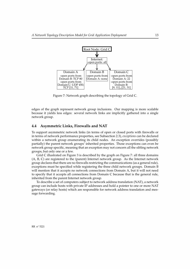
Figure 7: Network graph describing the topology of Grid C.
edges of the graph represent network group inclusions. Our mapping is more scalablebecause it yields less edges: several network links are implicitly gathered into a singlenetwork group.
4.4 Asymmetric Links, Firewalls and NATTo support asymmetric network links (in terms of open or closed ports with firewalls orin terms of network performance properties, see Subsection 2.3), exceptions can be declaredwithin a network group enumerating its child nodes. An exception overrides (possiblypartially) the parent network groups’ inherited properties. Those exceptions can even benetwork group specific, meaning that an exception may not concern all the sibling networkgroups, but only one or a few.
Grid C illustrated on Figure 3 is described by the graph on Figure 7: all three domains(A, B, C) are registered to the (parent) Internet network group. As the Internet networkgroup declares that there are no firewalls restricting the communications (as a general rule),exceptions must be specified while registering the three child network groups. Domain Bwill mention that it accepts no network connections from Domain A, but it will not needto specify that it accepts all connections from Domain C because that is the general rule,inherited from the parent Internet network group.
To describe a set of computers subject to network address translation (NAT), a networkgroup can include hosts with private IP addresses and hold a pointer to one or more NATgateways (or relay hosts) which are responsible for network address translation and mes-sage forwarding.
RR n° 5221

14 Sébastien Lacour, Christian Pérez, Thierry Priol
5 ImplementationThis section deals with practical issues. First, it shows that the proposed model is quite sim-ple to integrate into an existing resource information service. Second, the implementationand the model are validated by registering examples of grids.
We chose to extend version 2 of MDS to describe grid network topologies following ourmodel because MDS2 is widely deployed and applied, flexible and easily extensible. MDS2also permits new network groups to register dynamically to the grid. However, our gridnetwork description model is not bound to MDS2: we simply handle XML descriptors,which can be stored by any means, including MDS, description files accessed through theHTTP protocol (possibly HTTPS), etc. We could also have expressed our description byusing an extension of RDF (Resource Description Framework, [21]), an XML dialect usedto describe the metadata information about the resources of a grid.
5.1 Network Group ManagerThe information concerning a network group is held by a computer called the “networkgroup manager” chosen by a network group administrator. This manager must be acces-sible (i.e., with no firewall obstructing communications) from the application deploymentclient which needs the information held by the manager to select resources.
Updating and maintaining the network topology and performance properties is easieras information is gathered in one point (thanks to network grouping) for a whole networkgroup rather than scattered on each network link description. More than one managermay be chosen for fault tolerance reasons, but that would require to maintain consistencyamong the information held by the all the managers of a network group.
5.2 MDS2-only ImplementationIn an earlier implementation, the network topology description graph was mapped to ahierarchical MDS: the child network groups maintained a list of parent nodes which theywere registered to, and parent network groups also maintained a list of their child nodes.MDS2 already provides the list of child nodes registered to a parent node, using grid-info-search -s base giisregistrationstatus. We just needed to add a simpleInformation Provider script into MDS2 to find out the list of the parent nodes by read-ing an already existing MDS2 configuration file, namely etc/grid-info-resource-registration.conf.
We described the new data we needed to add into MDS2.4 by defining LDAP schemaentries: around 40 LDAP schema entries were added to describe the network topology. Theextended version of MDS2 remained inter-operable with the original MDS2.
INRIA

A Network Topology Description Model for Grid Application Deployment 15
5.3 Implementation Indenpendent of Grid TechnologyThe earlier implementation required consistency to be maintained among the informationheld by the parent and child network groups, since there was a double linkage from the par-ent groups referencing their children and from the child groups referencing their parents.So we moved to another implementation, which is not bound to MDS2 any longer. Thelatter implementation does not map the network topology description graph to a hierar-chical MDS: the description graph is made of a set of distributed XML descriptors, possiblyhosted by a single binary LDAP entry in MDS2. By doing so, we lose the filtering capabili-ties of LDAP, since all the information held by an MDS server is contained in an XML filewhich an LDAP server cannot parse. However, we make it easier for a future transition toGlobus3/OGSI or Globus4/Web Services, and we find it more convenient to handle XMLrather than LDAP format, especially with the powerful XML filtering capabilities of Xpathor Xquery.
As shown on Figure 8, the XML descriptor essentially holds two kinds of elements: gridnodes and GIS references (grid information service). Grid nodes correspond to network groups:they can be structural or represent a computational resource, accessed using a Globus2gatekeeper for instance, but other job submission methods are also possible (like SSH). Astructural grid node is simply a list of child network groups: those child grid nodes may bedescribed in the same XML file or in an XML descriptor which can be obtained using a GISreference. A GIS reference is a method for retrieving an XML descriptor, using either MDS2or HTTP, etc.
In the XML descriptor, the parents have pointers to their child network groups. Theprogram which reads this information and parses the XML data maintains a double linkagefrom the parent to the child grid nodes, and from the children to the parent network groups.This double linkage allows to find out whether and how two computers can communicatewith each other (we just need to scan all their common parent network groups) and toretrieve all the computers which belong to a network group (using the list of child gridnodes).
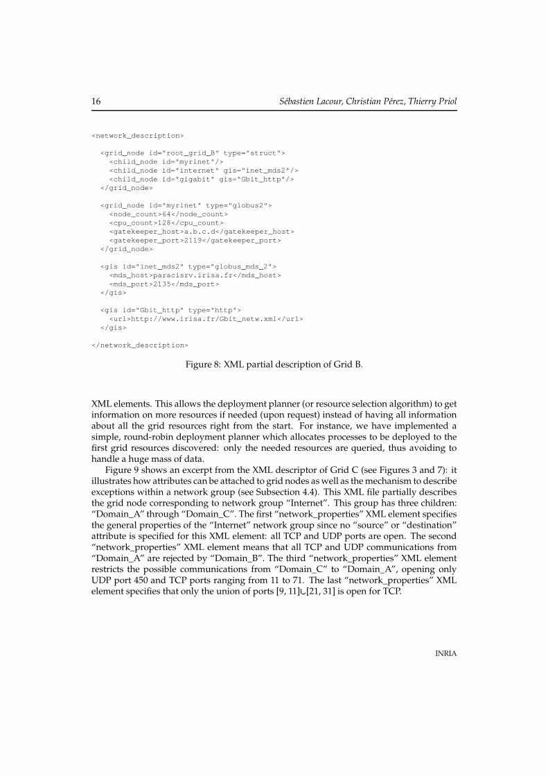
A network topology XML descriptor can be retrieved from MDS2, from a local file, fromHTTP or HTTPS protocols. Future extensions may allow more XML information sources.Currently, an XML descriptor may contain the description of one or several grid nodes, andit may also point to other, distributed XML information sources (HTTP reference, MDS2pointer, etc.) Figure 8 shows a partial description of Grid B (see Subsection 2.2). Two gridnodes are defined in this XML file:
• “root_grid_B” is a structural network group which has three child network groups,“myrinet”, “internet”, “gigabit”;
• “myrinet” is a grid node which represents a computational resource with 128 CPUsand a Globus2 gatekeeper for job submission.
The child network nodes “internet” and “gigabit” are described in other XML descriptors,which can be obtained respectively through MDS2 and HTTP, as specified by the two GIS
RR n° 5221
16 Sébastien Lacour, Christian Pérez, Thierry Priol
<network_description>
<grid_node id="root_grid_B" type="struct"><child_node id="myrinet"/><child_node id="internet" gis="inet_mds2"/><child_node id="gigabit" gis="Gbit_http"/>
</grid_node>
<grid_node id="myrinet" type="globus2"><node_count>64</node_count><cpu_count>128</cpu_count><gatekeeper_host>a.b.c.d</gatekeeper_host><gatekeeper_port>2119</gatekeeper_port>
</grid_node>
<gis id="inet_mds2" type="globus_mds_2"><mds_host>paracisrv.irisa.fr</mds_host><mds_port>2135</mds_port>
</gis>
<gis id="Gbit_http" type="http"><url>http://www.irisa.fr/Gbit_netw.xml</url>
</gis>
</network_description>
Figure 8: XML partial description of Grid B.
XML elements. This allows the deployment planner (or resource selection algorithm) to getinformation on more resources if needed (upon request) instead of having all informationabout all the grid resources right from the start. For instance, we have implemented asimple, round-robin deployment planner which allocates processes to be deployed to thefirst grid resources discovered: only the needed resources are queried, thus avoiding tohandle a huge mass of data.
Figure 9 shows an excerpt from the XML descriptor of Grid C (see Figures 3 and 7): itillustrates how attributes can be attached to grid nodes as well as the mechanism to describeexceptions within a network group (see Subsection 4.4). This XML file partially describesthe grid node corresponding to network group “Internet”. This group has three children:“Domain_A” through “Domain_C”. The first “network_properties” XML element specifiesthe general properties of the “Internet” network group since no “source” or “destination”attribute is specified for this XML element: all TCP and UDP ports are open. The second“network_properties” XML element means that all TCP and UDP communications from“Domain_A” are rejected by “Domain_B”. The third “network_properties” XML elementrestricts the possible communications from “Domain_C” to “Domain_A”, opening onlyUDP port 450 and TCP ports ranging from 11 to 71. The last “network_properties” XMLelement specifies that only the union of ports [9, 11] � [21, 31] is open for TCP.
INRIA

A Network Topology Description Model for Grid Application Deployment 17
<network_description>
<grid_node id="Internet" type="struct">
<child_node id="Domain_A"/><child_node id="Domain_B"/><child_node id="Domain_C"/>
<network_properties udp_port_policy="allopen" tcp_port_policy="allopen"/>
<network_properties source="Domain_A" destination="Domain_B"udp_port_policy="allclosed" tcp_port_policy="allclosed"/>
<network_properties source="Domain_C" destination="Domain_A"udp_port_policy="allclosed" tcp_port_policy="allclosed">
<udp_ports><min_port>450</min_port><max_port>450</max_port>
</udp_ports><tcp_ports>
<min_port>11</min_port><max_port>71</max_port>
</tcp_ports></network_properties>
<network_properties source="Domain_B" destination="Domain_C"tcp_port_policy="allclosed">
<tcp_ports><min_port>9</min_port><max_port>11</max_port>
</tcp_ports><tcp_ports>
<min_port>21</min_port><max_port>31</max_port>
</tcp_ports></network_properties>
</grid_node>
</network_description>
Figure 9: XML partial description of Grid C.
RR n° 5221

18 Sébastien Lacour, Christian Pérez, Thierry Priol
Our network topology description model could host the description of any mix ofGrid A, Grid B, Grid C, Grid D (see Section 2) we could imagine.
6 Conclusion and Future WorkThe actual, efficient utilization of grids depends on an effective deployment of applicationson grid resources. One major source of difficulty stems from the heterogeneity of the resourcesincluding compute nodes and networks. While the description of the compute nodes of a gridis relatively well mastered, the network description of grids is not yet suitable for constraineddeployments of applications on grids.
This paper has presented a description model for grid networks. This model providesa synthetic view of the network topology. The model which we propose is also simple,namely thanks to the possibility for a network group to inherit properties from its par-ent network groups. However, this simplicity does not hinder the description of complexnetwork topologies (asymmetric links, firewalls, non-IP networks, non-hierarchical topolo-gies). Finally, our description model aims to be complete by including the necessary infor-mation about the software available to access particular network technologies and allowingfor specification of network performance properties.
This model is useful not only to deploy applications (resource selection, see [39]), butalso to schedule algorithms by making proper decisions [10, 9, 43] as well as for grid gen-erators designed for simulation [29].
Our next step is to focus on a model for automatic deployment of component-basedapplications on a computational grid [24]. The software component model [41, 4, 34] whichadvocates a programming model based on the composition of (reusable and) independentunits of deployment emphasizes the deployment phase as a separate step, independent ofthe programming phase. To this end, an adequate network topology model is required.However, we will probably need to extend the component assembly description as networkconstraints are generally not taken into account.
References[1] Gabrielle Allen, Kelly Davis, Konstantinos N. Dolkas, Nikolaos D. Doulamis, Tom
Goodale, Thilo Kielmann, André Merzky, Jarek Nabrzyski, Juliusz Pukacki, ThomasRadke, Michael Russell, Ed Seidel, John Shalf, and Ian Taylor. Enabling applicationson the grid: a GridLab overview. International Journal of High Performance ComputingApplications (JHPCA), special issue on Grid Computing: Infrastructure and Applications,17(4), August 2003.
[2] Giovanni Aloisio, Massimo Cafaro, Italo Epicoco, and Sandro Fiore. Analysis of theGlobus Toolkit grid information service. Technical Report GridLab-10-D.1-0001-1.0,
INRIA

A Network Topology Description Model for Grid Application Deployment 19
HPCC, University of Lecce, Italy, 2002. available at http://www.gridlab.org/Resources/Deliverables/D10.1.pdf.
[3] Giovanni Aloisio, Massimo Cafaro, Italo Epicoco, Daniele Lezzi, Maria Mirto, SilviaMocavero, and Serena Pati. First GridLabMDS release. Technical Report GridLab-10-D.3-0001-1.0, HPCC, University of Lecce, Italy, 2002. available at http://www.gridlab.org/Resources/Deliverables/D10.3c.pdf.
[4] Rob Armstrong, Dennis Gannon, Al Geist, Katarzyna Keahey, Scott Kohn, LoisMcInnes, Steve Parker, and Brent Smolinski. Toward a common component archi-tecture for high-performance scientific computing. In Proc. of the 8th IEEE InternationalSymp. on High Performance Distributed Computing (HPDC’99), pages 13–22, RedondoBeach, CA, August 1999.
[5] Nanette J. Boden, Danny Cohen, Robert E. Felderman, Alan E. Kulawik, Charles L.Seitz, Jakov N. Seizovic, and Wen-King Su. Myrinet: A gigabit-per-second local areanetwork. IEEE Micro, 15(1):29–36, February 1995.
[6] Yuri Breitbart, Minos N. Garofalakis, Cliff Martin, Rajeev Rastogi, S. Seshadri, andAbraham Silberschatz. Topology discovery in heterogeneous IP networks. In Proc. ofIEEE INFOCOM’2000, pages 265–274, Tel-Aviv, Israel, March 2000.
[7] Matthias Brune, Alexander Reinefeld, and Jörg Varnholt. A resource description envi-ronment for distributed computing systems. In Proc. of the 8th IEEE International Symp.on High Performance Distributed Computing (HPDC’99), pages 279–286, Redondo Beach,CA, August 1999.
[8] Kenneth L. Calvert, Matthew B. Doar, and Ellen W. Zegura. Modeling internet topol-ogy. IEEE Communications Magazine, 35(6):160–163, June 1997.
[9] Henri Casanova and Fran Berman. Grid Computing: Making the Global Infrastructure aReality, chapter 33 (Parameter Sweeps on the Grid with APST). Wiley & Sons, April2003.
[10] Henri Casanova, Graziano Obertelli, Francine Berman, and Richard Wolski. The Ap-pLeS parameter sweep template: User-level middleware for the grid. In Proc. of Super-computing 2000, pages 75–76, Dallas, TX, November 2000.
[11] R. L. Cottrell, Connie Logg, and I-Heng Mei. Experiences and results from a new highperformance network and application monitoring toolkit. In Proc. of the Passive andActive Measurement Workshop (PAM2003), pages 205–217, La Jolla, CA, April 2003.
[12] Karl Czajkowski, Steven Fitzgerald, Ian Foster, and Carl Kesselman. Grid informationservices for distributed resource sharing. In Proc. of the 10th IEEE International Symp. onHigh-Performance Distributed Computing (HPDC-10’01), pages 181–194, San Francisco,California, August 2001. IEEE Computer Society.
RR n° 5221

20 Sébastien Lacour, Christian Pérez, Thierry Priol
[13] Mathijs den Burger, Thilo Kielmann, and Henri E. Bal. TopoMon: A monitoring toolfor grid network topology. In Proc. of the International Conf. on Computational Science,part 2 (ICCS2002), number 2330 in LNCS, pages 558–567, Amsterdam, The Nether-lands, April 2002. Springer.
[14] Peter Dinda and Beth Plale. A unified relational approach to grid information services.Informational Draft GWD-GIS-012-1, Global Grid Forum, February 2001.
[15] Matthew B. Doar. A better model for generating test networks. In Proc. of the IEEEGlobal Telecommunications Conference / Globecom’96, London, UK, November 1996.
[16] Nathalie Furmento, Anthony Mayer, Stephen McGough, Steven Newhouse, TonyField, and John Darlington. Optimisation of component-based applications withina grid environment. In Proc. of the 2001 ACM/IEEE Conf. on Supercomputing, page 30,Denver, CO, November 2001. ACM Press, New York, NY, USA.
[17] Nathalie Furmento, Anthony Mayer, Stephen McGough, Steven Newhouse, TonyField, and John Darlington. ICENI: Optimisation of component applications withina grid environment. Journal of Parallel Computing, 28(12):1753–1772, 2002.
[18] The Globus Alliance: http://www.globus.org/.
[19] Web site of the ENV project at SDSC, CA: http://grail.sdsc.edu/projects/env/GridML.html.
[20] The Grid Physics Network (GriPhyN) web site: http://www.GriPhyN.org/.
[21] Dan Gunter and Keith Jackson. The applicability of RDF-schema as a syntax for de-scribing grid resource metadata. Informational Draft GWD-GIS-020-1, Global GridForum (GGF), June 2001.
[22] Axel Keller and Alexander Reinefeld. Anatomy of a resource management system forHPC clusters. Technical Report 00-38, Konrad-Zuse-Zentrum für InformationstechnikBerlin (ZIB), Germany, November 2000.
[23] Tatiana Kichkaylo, Anca-Andreea Ivan, and Vijay Karamcheti. Constrained compo-nent deployment in wide-area networks using AI planning techniques. In Proc. of the17th International Parallel and Distributed Processing Symp. (IPDPS’2003), page 3, Nice,France, April 2003.
[24] Sébastien Lacour, Christian Pérez, and Thierry Priol. Deploying CORBA componentson a computational grid: General principles and early experiments using the GlobusToolkit. In Wolfgang Emmerich and Alexander L. Wolf, editors, Proc. of the 2nd Inter-national Working Conference on Component Deployment (CD 2004), volume 3083 of LNCS,pages 35–49, Edinburgh, Scotland, UK, May 2004. Springer-Verlag. Held in conjunc-tion with the 26th International Conference on Software Engineering (ICSE 2004).
INRIA

A Network Topology Description Model for Grid Application Deployment 21
[25] Chuang Liu, Lingyun Yang, Ian Foster, and Dave Angulo. Design and evaluation of aresource selection framework for grid applications. In Proc. of the 11th IEEE Symp. onHigh Performance Distributed Computing (HPDC-11), pages 63–52, Edinburgh, Scotland,July 2002.
[26] Bruce Lowekamp, Brian Tierney, Les Cottrell, Richard Hughes-Jones, Thilo Kielmann,and Martin Swany. A hierarchy of network performance characteristics for grid appli-cations and services. Proposed Recommendation Global Grid Forum (GGF), NetworkMeasurement Working Group (NMWG), January 2004.
[27] Bruce B. Lowekamp, Nancy Miller, Dean Sutherland, Thomas Gross, Peter Steenkiste,and Jaspal Subhlok. A resource query interface for network-aware applications. Jour-nal of Cluster Computing, 2(2):139–151, 1999.
[28] Bruce B. Lowekamp, Brian Tierney, Les Cottrell, Richard Hughes-Jones, Thilo Kiel-mann, and Martin Swany. Enabling network measurement portability through a hi-erarchy of characteristics. In Proc. of the 4th International Workshop on Grid Computing(Grid2003), pages 68–75, Phoenix, AZ, November 2003. IEEE.
[29] Dong Lu and Peter A. Dinda. Synthesizing realistic computational grids. In Proc. ofSuperComputing 2003 (SC’03), Phoenix, AZ, November 2003.
[30] Muthucumaru Maheswaran and Howard Jay Siegel. A dynamic matching andscheduling algorithm for heterogeneous computing systems. In Proc. of the 7th Het-erogeneous Computing Workshop, held in conjunction with IPPS/SPDP’98, pages 57–69,Orlando, FL, March 1998.
[31] Myricom. GM: A Message-Passing System for Myrinet Networks. reference manual, avail-able at http://www.myri.com/scs/GM-2/doc/html/.
[32] Myricom. Myrinet Express (MX): A High-Performance, Low-Level, Message-Passing Inter-face for Myrinet, July 2003. pre-release, available at http://www.myri.com/scs/#documentation.
[33] Katia Obraczka and Grig Gheorghiu. The performance of a service for network-awareapplications. In Proc. of the 2nd ACM Symp. on Parallel and Distributed Tools (SPDT’98),pages 81–91, Welches, Oregon, USA, August 1998.
[34] Christian Pérez, Thierry Priol, and André Ribes. A parallel CORBA component modelfor numerical code coupling. The International Journal of High Performance Comput-ing Applications (IJHPCA), 17(4):417–429, 2003. Special issue Best Applications Papersfrom the 3rd International Workshop on Grid Computing.
[35] Loïc Prylli and Bernard Tourancheau. BIP: a new protocol designed for high perfor-mance networking on Myrinet. In Proc. of the 1st Workshop on Personal Computer basedNetworks Of Workstations (PC-NOW’98), Lecture Notes in Computer Science, pages472–485. Springer-Verlag, April 1998. Held in conjunction with IPPS/SPDP 1998.
RR n° 5221

22 Sébastien Lacour, Christian Pérez, Thierry Priol
[36] Rajesh Raman, Miron Livny, and Marvin Solomon. Matchmaking: Distributed re-source management for high throughput computing. In Proc. of the 7th IEEE Inter-national Symp. on High Performance Distributed Computing (HPDC7), pages 140–146,Chicago, IL, July 1998.
[37] Gary Shao, Fran Berman, and Rich Wolski. Using effective network views to promotedistributed application performance. In Proc. of the 1999 International Conf. on Paralleland Distributed Processing Techniques and Applications (PDPTA’99), June 1999.
[38] Pyda Srisuresh and Matt Holdrege. IP network address translator (NAT) terminologyand considerations. Informational RFC 2663, IETF Network Working Group, August1999.
[39] Jaspal Subhlok, Peter Lieu, and Bruce Lowekamp. Automatic node selection for highperformance applications on networks. In Proc. of the 7th ACM SIGPLAN Symp. onPrinciples and Practice of Parallel Programming (PPoPP’99), pages 163–172, Atlanta, GA,May 1999.
[40] Martin Swany and Rich Wolski. Representing dynamic performance information ingrid environments with the network weather service. In Proc. of the 2nd IEEE/ACMInternational Symp. on Cluster Computing and the Grid (CCGrid’02), pages 48–56, Berlin,Germany, May 2002.
[41] Clemens Szyperski. Component Software: Beyond Object-Oriented Programming.Addison-Wesley / ACM Press, first edition, 1998.
[42] TeraGrid web site: http://www.TeraGrid.org/.
[43] Jon B. Weissman and Xin Zhao. Scheduling parallel applications in distributed net-works. Journal of Cluster Computing, 1(1):109–118, May 1998.
[44] Rich Wolski, Neil Spring, and Jim Hayes. The Network Weather Service: a distributedresource performance forecasting service for metacomputing. Journal of Future Gener-ation Computing Systems, 15(5-6):757–768, October 1999.
INRIA

Unité de recherche INRIA RennesIRISA, Campus universitaire de Beaulieu - 35042 Rennes Cedex (France)
Unité de recherche INRIA Futurs : Parc Club Orsay Université - ZAC des Vignes4, rue Jacques Monod - 91893 ORSAY Cedex (France)
Unité de recherche INRIA Lorraine : LORIA, Technopôle de Nancy-Brabois - Campus scientifique615, rue du Jardin Botanique - BP 101 - 54602 Villers-lès-Nancy Cedex (France)
Unité de recherche INRIA Rhône-Alpes : 655, avenue de l’Europe - 38334 Montbonnot Saint-Ismier (France)Unité de recherche INRIA Rocquencourt : Domaine de Voluceau - Rocquencourt - BP 105 - 78153 Le Chesnay Cedex (France)
Unité de recherche INRIA Sophia Antipolis : 2004, route des Lucioles - BP 93 - 06902 Sophia Antipolis Cedex (France)
ÉditeurINRIA - Domaine de Voluceau - Rocquencourt, BP 105 - 78153 Le Chesnay Cedex (France)
http://www.inria.frISSN 0249-6399